We recall from previous classes that in order for us to understand Photovoltaic technology, we need to understand its main properties at the cell level such as the Photovoltaic effect, the P-N Junction to simply convert light into electricity, and how PV performance is measured in terms of current and voltage (I-V) curve, Filling factor (FF), and efficiency.
In this section, we will revisit some of these performance characteristics, such as I-V, P-V, FF, and efficiency, at the module level.
Before we start, let us define some of the commonly used terminologies in solar at the system level.
Review:
To learn more about the basics of PV in detail, you can refer to EME 812 (4.1 Photovoltaic effect) and EME 812 (4.2 P-N Junction).
Modules and Panels
In this lesson, we will focus on the centerpiece of any PV system, which is the PV module. Solar modules or solar panels are two commonly used terms in the solar industry. Many people use these terms interchangeably, but there is a small difference that should be discussed. A module is the series and/or parallel interconnection of solar cells in a circuit, on a panel. The term solar panel is more exclusive to the rectangular, rigid packaging frame. Most standard crystalline modules can be called solar panels. In general, all solar panels are solar modules, but the opposite is not always true. For example, a thin-film silicon solar cell that is packaged as a flexible laminate is a solar module, but it is not a panel.
Array
Another important term to consider is PV array. When modules are installed as a system, that layout is called an array. Arrays can also be connected in parallel or in series similar to modules and cells.
Review:
To learn more about cell series and parallel characteristics, you can refer to EME 812 (4.4 PV systems across scale). In addition, Chapter 14 of Jeffrey Brownson's Solar Energy Conversion Systems dives into more of these terms in greater detail. (Note: a link to the reading is available under "Recommended Readings" on the first page of the lesson.)
A Module's Main Parameters
Since a solar module is nothing but an interconnection of solar cells, similar parameters are defined such as module Efficiency, module Fill Factor, Maximum Power Point (MPP) Voltage and Current (Vmpp) and (Impp), Open Circuit Voltage (Voc), and Short Circuit Current (Isc).
Voltage and Current of a Module
As we can see, the total voltage of a PV module is nothing but a scale version of the cell voltage (multiplied by a number of cells connected in series), while the total current is a scaled version of the cell current (multiplied by a number of strings of cells connected in parallel).
Module I-V characteristics
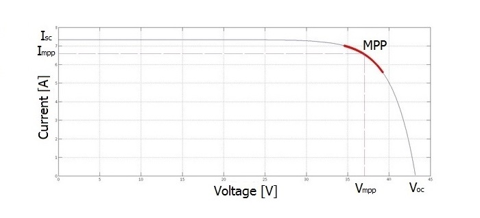
Previously, we learned about the I-V (J-V in some references, “J” being the current density, current per unit area) curve at the solar cell level. However, in PV systems, we are more interested in the total current and voltage that the PV module can generate, so we define the Module I-V curve, or the current-voltage curve, as it is illustrated in Figure 2.1. The curve indicates the voltage and current at different operating conditions. For example, the highest current corresponds to the short-circuit condition (when a PV module's positive and negative terminals are connected without load, causing very high current to pass), while the highest voltage occurs at open-circuit condition (when a PV module's positive and negative terminals are not connected to any load, causing no current to pass). If we observe the current and voltage starting at the open-circuit condition (where voltage is maximum and current is zero), and as we increase the load of the circuit, the current starts increasing and the voltage falls down until it reaches the value of zero at short-circuit condition (where the current is maximum). The knee of the curve indicates the operating condition in which current and voltage result in maximum power point (MPP). The voltage and current values at MPP are referred to as "Vmpp” and “Impp,” respectively.
Review:
To learn more about the current and voltage relationship in detail, you can refer to EME 812 (4.3. How PV performance is measured).
Module P-V characteristics
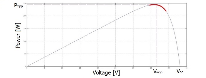
Another way to visualize the I-V curve is to convert it to a relationship between power and voltage. In this case, we can call it (P-V) curve of PV module, as shown in Figure 2.2. Similar to an I-V curve, the highest voltage occurs at the open-circuit condition and the current is zero and the short-circuit voltage is zero at the origin of the curve, but the current is maximum. Since the power is nothing but the voltage times the current (P=VxI), the power at both the short-circuit and open-circuit conditions is equal to zero since either voltage or current equals zero at each of these points. If we observe the power and voltage starting at the open-circuit condition (where the voltage is maximum and power is zero), and as we increase the load of the circuit, the power starts increasing and the voltage falls down until it reaches the value at MPP (where power is maximum). If we increase the load further, the voltage keeps falling down. However, the power will decrease as well until it reaches the value of zero at short-circuit condition (where the both voltage and power are zero). It can be seen that it is much easier to find the peak power on the P-V curve in comparison to the I-V curve, as it resembles a hump. The power at MPP is referred to as "Pmpp."
Reflection
In Figures 2.1 and 2.2, what does the highlighted red line on the I-V and P-V curves refer to?
ANSWER: The highlighted red line shows the range the voltage can vary around the Maximum Power Point (MPP).
Other Parameters of PV Modules
But what about the other parameters, such as efficiency and fill factor of a solar module? Do they increase, decrease or stay the same in comparison to the cell values? Ideally, all cells have similar characteristics with no mismatching losses; in this case, we expect the efficiency and fill factor at both of the module and cell levels to be the same. But this is not true in practice due to various factors that play a role when cells are interconnected, such as the series resistance caused by contacts soldering between cells. Furthermore, there might be a small manufacturer mismatch in the characteristics of the cells that are interconnected. In this case, the cell with the lowest current in the string in series dictates the current of the module. Similarly, the cell with the lowest voltage in parallel dictates the voltage of the module. This mismatch in cells can be a result of the non-homogeneity of the cells due to mass production.
Another main cause of mismatch occurs when a module is:
- partly shaded, or
- has non-uniform irradiance, or
- has non-uniform heating on the cell level.
Therefore, each module in practice performs a little different compared to the expected performance of the ideally matched solar cells.
So how does this affect the parameters of the Module?
Most module manufacturers list in their datasheets the difference between module and cell level efficiency. For example, the datasheet of the Sanyo HIT-N240SE10 module states that cell efficiency is 21.6% and that module level efficiency is around 19%.
Review:
To learn more about the cell technology and efficiency in detail, you can refer to EME 812 (4.5 Types of PV technology and recent innovation).