Connections at the Module Level
Now that we have covered the basics of series and parallel connections of PV cells when we discussed the I-V characteristics, it is time to understand the bigger picture by investigating the connections at the module level. In this lesson, we will define a new commonly used term in the solar PV industry, which is the PV string. We will look at how the total voltage and current characteristics change as a result of these formations. In addition, we will discuss how characteristics are affected by the pattern of shading applied to the PV system.
A PV string is formed when multiple modules are connected in series. In this case, the string I-V curve is the same as the individual I-V curve of each module, but it is scaled in voltage by the number of modules connected in series while the current stays similar to the individual module’s current. PV strings can be as small as one module, or can have multiple numbers of modules in series. When strings are combined in parallel form, that leads to a scaled current by the number of strings, while voltage equals the individual string’s voltage. A PV system can consist of a single string or multiple strings, depending on the size of the system.
Blocking Diode
Moving to the shading effect on PV systems, similar to the modules level effect, when one module is shaded within the string, the entire string can lose power by the restriction of current flowing through the string. As the modules solution suggested, the bypass diodes will clear the shading effect by bypassing the shaded module. As a result, that will have a voltage drop impact on the total string voltage that may interfere with the other parallel strings within the system, since equivalent array voltage is dictated by the string with the lowest voltage.
Reflection
What about the scenario when we have a row of shading that covers the same number of modules on each string?
ANSWER: In this case, all strings will experience a voltage drop in the same amount, and that will be a better scenario than having one shaded string.
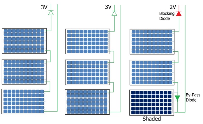
For that reason, some designers choose to add a blocking diode to prevent the current from flowing back to the weak string, and that will eliminate fire hazards as well. Figure 2.6 illustrates the bypass and blocking diodes at the system level and how the total voltage is affected by it. We can see nine PV modules wired to form a PV array. Each group of three modules is connected in series to form a string, for a total of three strings. Each module uses a dedicated bypass diode that only actives when the module is shaded. For example, in Figure 2.6, there is a green colored triangular shape that represents the bypass diode. That is associated with the shaded module illustrated in dark blue in the bottom left corner of Figure 2.6. We can also see red colored triangles that represent the blocking diodes in series with each group to protect the entire string. Assuming each module generates 1V, the unshaded strings generate a total of 3V while the shaded string can only generate 2V (due to the bypass diode effect ). In this case, the blocking diode will protect the shaded string from draining current from the unshaded strings.
Reflection
How does a blocking diode help for PV systems with batteries?
ANSWER: When the sun is not shining, PV modules can act like a load at night. Current can flow back to the PV module so the blocking diode prevents the current from flowing back into the modules and damage it.
Design Recommendations
Finally, as PV designers, we should avoid all types of shading that includes:
- Inter-row shading: as discussed in EME 810 (Lesson 2: Applying Shading to a Solar Chart).
- Soft shading: that can be caused by Trees and moving objects. A solution to that is Tree trimming.
- Hard shading: such as chimneys or pipes, and this should be completely avoided for optimum design.
Review
You may refer to EME 812 (4.4 PV systems across scale) for more information about the cell connections within modules and to visualize how array and strings are formed.