Lesson 4: PV System Components (Power Conditioning Units)
Overview
Lesson 4 Scenario
You are still attending the solar trade show. Now you are looking for solar inverters. The inverter manufacturer representative discusses the datasheets and series of inverters that best fit the PV modules you selected. You learn manufacturers make various types of inverters. What is the first question you ask to narrow down your choices of Inverters in terms of inverter types based on what was discussed in class? Are there different types that can be detrimental to your PV module selection?
You leave the trade show with more specification sheets from other inverter manufacturers. The next day, you need to prepare a report to your director with more information to help him choose the best PV inverter for the company. As always, you need to come up with the right tools to evaluate the inverters.
Ignoring the cost of the inverter, is it the inverter's efficiency, dimensions, ambient conditions, technical features, warranty, or color that are considered when selecting an inverter?
Can any inverter be connected to the utility grid, or should it have some kind of tests and certifications? Are there specific grid requirements for the US?
In this lesson, we will discuss topics that lead to answers to all the questions in the scenario above. We will also introduce new tools that can be used to help PV designers make the optimum selection of the inverter. Whether you are a designer or a system owner, the knowledge presented in this lesson will help you understand the basics of the inverter.
Learning Outcomes
At the successful completion of this lesson, students should be able to:
- Identify common types and functions of inverters, converters, and power management technologies and selection methods to align with PV systems.
- Interpret inverter specification sheets and parameters to match PV and grid requirements.
- Discuss features of inverters, including the Maximum PowerPoint Tracker, anti-islanding detection.
- Describe factors influencing the lifetime of an inverter, such as temperature and environment.
- Identify an inverter’s voltage operating ranges and capacity factor and how to match them with PV module and string ranges.
What is due for Lesson 4?
Lesson 4 will take us one week to complete. Please refer to the Calendar in Canvas for specific time frames and due dates. Specific directions for the assignments below can be found within this lesson and/or in Canvas.
Complete the following Lesson Assignments:
- Read through the Lesson Content
- Complete the Required Reading Assignments:
- Chapter 8, Photovoltaic Systems by James P. Dunlop (text)
- Complete the Lesson 4 Activity
- Complete Procurement Report (Parts A, B, C)
- Take the Lesson 4 Quiz in Canvas
Questions?
If you have lesson specific questions, please feel free to post to the Lesson 4 Questions discussion forum in Canvas. While you are there, feel free to post your own responses if you, too, are able to help a classmate with a question. If you have questions about the overall course or wish to share and discuss any "extra" course related commentary (interesting articles, etc.), please feel free to post to the General Questions and Discussion forum.
Review
Some of the content in AE 868 is directly related to topics that are already discussed in other courses. However, these topics are essential building blocks on what we will cover in AE 868. Many lessons will begin with a list that links out to these relevant topics. Please take the time to review the topics here or where noted throughout the lesson.
Why Power Conditioning Units for PV?
Since we learned the difference between DC power and AC power and their properties in the “Basics of Electricity” section in the class Orientation, we know for sure that the power coming from the source needs to be shaped to match the property of the load.
In this lesson, we will focus on how Power Conditioning Units (PCUs) are used and what the main types and configurations are that exist for these PCUs in the solar industry.
PCUs for PV systems
To know what a PCU is, we must first understand we need it for PV systems. All topics on the PV electrical output current, voltage, and power we discussed were in DC form. And since most appliances (fridge, lighting, heating, etc) need AC power, we need a device that can simply convert the DC electric power into an AC power. And that device is called an inverter. Furthermore, since most PV systems are connected to the utility grid, the solar power produced needs to be converted to AC form. This allows solar power to move in and out of the electricity grids we have today.
PCU vs Inverter
Many people use the term inverter as a device that converts DC into AC power. However, the inverter can perform many tasks beyond that. Thanks to the advancements in power electronics, it is common to have inverters that implement an MPPT mechanism before inverting the voltage, thus ensuring that the PV modules or arrays are operating at their maximum power. Furthermore, the inverter can include a battery charger, a DC to DC converter for voltage step-up and step-down, and a transformer for grid isolation and voltage step-up. As we can see, the basic DC to AC conversion that is referred to as an inverter is better understood as the package and can be called a Power Conditioning Unit. It should be noted that the commonly used term for this device in the industry is “inverter.”
Note:
Power Conditioning Units are briefly discussed in EME 812 Lesson 6 PV Power Conditioning) [7] and the operating principles, switching devices, and parameters are thoroughly discussed in the same lesson.
Inverter types and classification
Now that we understand why we need an inverter for PV systems, it is time to introduce the different types of inverters that exist in the market and discover the advantages and disadvantages of each type. Inverters are classified based on their size, mode of operation, or configuration topology.
Inverters based on PV system type
Considering the classification based on the mode of operation, inverters can be classified into three broad categories:
- Stand-alone inverters (supplies stable voltage and frequency to load)
- Grid-connected inverters (the most commonly used option)
- Bimodal inverters (usually more expensive and are used less often)
Note
Inverter classification according to Interconnection types is discussed in EME 812 (11.4. Grid connection and role of inverters) [5].
Types of Grid-connected Inverters
Aside from the modes of operation, grid-connected inverters are also classified according to configuration topology. There are four different categories under this classification.
- Central inverters, which are usually around several kW to 100 MW range.
- String inverters, typically rated around a few hundred Watts to a few kW.
- Multi-string inverters, typically rated around 1 kW to 10 kW range.
- And finally, Module Inverters or Micro Inverters, typically rated around 50 to 500 W.
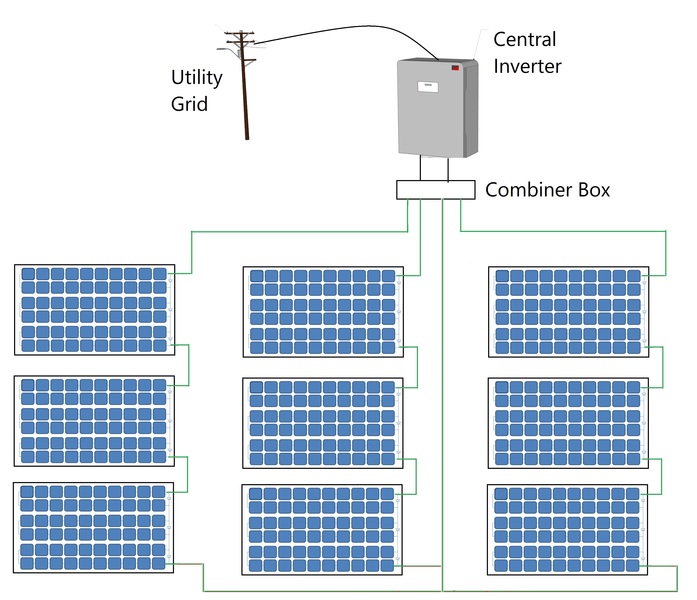
Central Inverter
Let's start with the central inverter, as shown in Figure 4.1. This is a PV array that consists of three strings, where each string has three series connected modules. Before these strings are connected to the utility grid, a power conditioning unit is required as an interface between the array and the grid. Designers can use one central inverter as illustrated in Figure 4.1, where all strings are connected to the DC side of the inverter and the single AC output is connected to the utility grid.
Advantages of a Central Inverter
- The most traditional inverter topology
- Easy system design and implementation
- Low cost per Watt
- Easy accessibility for maintenance and troubleshooting
Disadvantages of a Central Inverter
- High DC wiring costs and power loss due to Voltage Drop.
- Single MPPT for the entire PV system
- System output can be drastically reduced in case of partial shading and string mismatch
- Difficult to add strings or arrays for future expansion
- Single failure point for the entire system
- Monitoring at array level
- Huge size! (It is a disadvantage because the bigger size requires more land and creates a shading issue for the PV array.)
Reflection
What consequences can the size of a central inverter have on a PV array?
ANSWER: The huge size of a central inverter needs to be taken into account when designing the PV array to avoid a shading effect.
String Inverter
Now, we are moving to the String inverters as shown in Figure 4.2. Assuming the same PV array that consists of three strings, another way to connect it to the grid is using three string inverter as illustrated in Figure 4.2. In this case, each PV string is connected to a single string inverter at the DC side, and all AC outputs of inverters are combined and connected to the utility grid.
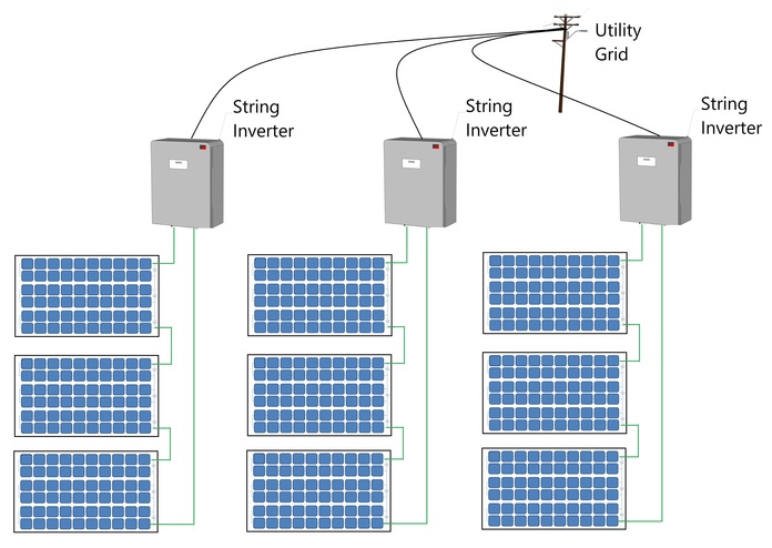
As the name indicates, each string of PV modules has its own inverter. In this case, we are moving closer to the PV modules level.
Advantages of a String Inverter
- Smaller in size when compared to central inverters
- Better MPPT capability per string
- Scalability for future expansion by adding parallel strings
- Short DC wires
- Monitoring at string level
Disadvantages of a String Inverter
- The installation requires special racking for the inverter for each string
- Poor flexibility at partial shading
- Higher per Watt cost than central inverter
Note:
There is another topology of string inverters called the multi-string inverter. It utilizes string DC-DC converter for MPPT and then central inverter. This type is not very common and is beyond our discussion for this class.
Micro Inverter
Finally, let's look at the micro inverters. These are also referred to as module inverters. In this case, each module has one dedicated inverter connected on the back of the module. The module DC terminals are connected to the DC side of the inverter and then all AC wires of all terminals are combined and then connected to the utility interconnection point as illustrated in Figure 4.3.
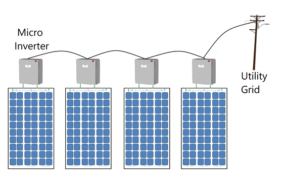
As the name suggests, each module has a dedicated inverter with an MPP tracker.
Advantages of Micro Inverters
- Resilience to partial shading effects as compared to the central and string inverters.
- MPPT at module level
- Highest system flexibility for future expansion
- Minimum DC wiring costs
- Monitoring at module level
Disadvantages of Micro Inverters
- High per Watt cost
- High maintenance costs
- Difficult access for maintenance since the installation is under the PV modules
Reflection
What consequences can the micro-inverter installation location have on the PV module?
ANSWER: Micro-inverters can increase the heat mass under the PV module.
Interpreting inverter datasheet and main parameters
After this overview of the solar inverters and their topologies, it is important to look at the various parameters and characteristics of this technology. The choice of the inverters' topology for implementation depends entirely on the system needs, size, and the budget. While choosing an inverter for your PV system, what are the requirements for a good solar inverter?
Characteristics of Solar Inverters
Inverter Input voltage range and max voltage
Inverters are designed to operate within a voltage range, which is set by the manufacturer's specification datasheet. In addition, the datasheet specifies the maximum voltage value of the inverter. Both the maximum voltage value and operating voltage range of an inverter are two main parameters that should be taken into account when stringing the inverter and PV array. PV designers should choose the PV array maximum voltage in order not to exceed the maximum input voltage of the inverter. At the same time, PV array voltage should operate within the input voltage range on the inverter to ensure that the inverter functions properly.
Inverter Start-up voltage
Aside from the operating voltage range, another main parameter is the start-up voltage. It is the lowest acceptable voltage that is needed for the inverter to kick on. Each inverter has a minimum input voltage value that cannot trigger the inverter to operate if the PV voltage is lower than what is listed in the specification sheet.
Reflection
Why is start-up voltage different from the minimum operating voltage for an inverter?
Click on “Click for answer…” to reveal the answer.
ANSWER
Power electronics switching devices need slightly more voltage to kick on when they start up in the morning. However, they are designed to allow lower voltage once they are in “ON” mode, and that is what we mean by the minimum operating voltage range.
Inverter and efficiency
As power is processed and converted from one shape to another, the solar inverters are expected to perform these tasks with the highest possible efficiency. This is because we wish to deliver maximum PV generated power to the load or the grid. Typical efficiencies are in the range of more than 95% at rated conditions specified in the datasheet.
Note:
Inverter efficiency is discussed in EME 812 (11.5. Efficiency of Inverters) [6].
Inverter and MPPT
Depending on the topology, most modern inverters have built-in MPP trackers to insure maximum power is extracted from the PV array. Each inverter comes with a voltage range that allows it to track the maximum power of the PV array. It is recommended to match that range when selecting the inverter and the PV array parameters.
Note:
Inverter MPPT is discussed in EME 812 (11.3 DC/DC Conversion) [4].
Inverter and ambient conditions
In most applications, the solar inverters are exposed to ambient conditions such as solar radiation, temperature, and humidity. Inverters must comply with the conditions of the location to make sure they can work under ambient conditions listed in the specification sheet.
Inverter and the utility grid
Since grid-tied inverters pump power into the grid, they are expected to maintain a very high quality of power to guarantee that the acceptable power flows into the grid. For that reason, inverters are expected to have a very low harmonic content on the line currents. Furthermore, grid-tied inverters are expected to have active islanding detection capability per IEEE 1547.
Islanding refers to the situation in which the inverters in a grid-tied setup continue to inject power from the PV system even though the power from the grid operator has been restricted due to fault of scheduled maintenance. Due to safety concerns, islanding needs to be prevented. Therefore, inverters are expected to detect and respond immediately by switching their output so that no more power flows into the grid. This is also referred to as anti-islanding capability.
Note:
Inverter grid features are discussed in EME 812 (11.4. Grid connection and role of inverters) [5].
Inverter lifetime
There is also ongoing work to increase the lifespan of the inverter. A good inverter will probably reach, under favorable conditions, around 10-12 years of lifetime. This is a bottleneck in the PV system lifetime, especially considering the fact that PV modules can last over 25 years.
Reflection
What are the solutions to the lower inverter lifetime when compared to the PV module lifetime?
ANSWER: Inverters need to be changed two to three times during the lifetime of the PV system. More research is being conducted to push inverters' lifetimes to longer periods.
DC to AC ratio
Each inverter comes with a maximum recommended PV power, or sometimes is referred to as "DC-AC Capacity factor," which is defined as the percentage of DC power over the inverter's max power. We will use "DC to AC ratio" when we refer to this specific term throughout this calss.
Stringing PV inverter
We discussed the effect of cell temperature on the I-V curve and the operating voltage and current in Lesson 2. Now it is time to apply this knowledge to calculate minimum and maximum operating voltage of module or string.
The NOCT and % temperature coefficients from the modules datasheet can be used to determine the min and max voltage levels and the range of MPP corresponding to it. PV designers are interested in the lowest recorded temperature for a location to determine the highest possible Voc for the string and Vmp for MPP range. Furthermore, the average highest temperature is used to find the lowest voltage from the module or string.
Note
Check out Weather.com. [8] On this site, you can search for the lowest and highest recorded temperatures by location.
We can also define the string voltage as the individual module’s voltage multiplied by the number of modules connected in series.
Assuming we are stringing the PV string shown in Figure 4.4, the I-V curves of the PV string vary depending on the temperature. When the temperature is higher than the standard 25ºC, both of the MPP voltage and the open circuit voltage Voc decrease. On the contrary, when the temperature is lower than 25ºC, both the MPP voltage and Voc increase, as illustrated in Figure 4.4. If we define operating ranges for both the MPP voltage and Voc, we can see that the inverter should be able to operate within the MPPT range at the lowest record and average highest MPP voltage of the PV string. Similarly, the inverter absolute maximum voltage should be at least equal to the maximum Voc of the string at the lowest record temperature and the minimum voltage of the inverter should not exceed the minimum Voc of the PV string at the highest temperature.
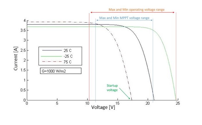
As PV designers, and when stringing the PV inverter with the PV string, we should make sure that the MPP voltage doesn't fall below the lowest voltage at the average high temperature and doesn't exceed the maximum voltage of the inverter.
Reflection
Example:
String the inverter with the following parameters:
- MPP voltage range between 250 – 480 V
- Maximum allowable voltage of 600V
- Startup voltage of 300V
What are the stringing voltage values of the PV string that a PV designer should consider? (Hint: Compare values to Figure 4.4, above)
ANSWER:
- Minimum open circuit voltage at average highest temperature doesn't fall bellow 300V to satisfy startup voltage requirements of the inverter.
- Minimum MPP voltage at average highest temperature doesn't fall bellow 250V to satisfy minimum MPPT voltage requirements of the inverter.
- Maximum open circuit voltage at lowest record temperature doesn't exceed 600V to satisfy maximum voltage requirements of the inverter.
- Maximum MPP voltage at lowest record temperature doesn't exceed 480V to satisfy maximum MPPT voltage requirements of the inverter.
Inverter stringing tool
As it seems, the math can get very tedious, so most Inverter manufacturers create their own sizing tools that are available online for free, where you can choose:
- PV module brand and model
- The desired inverter model
- The average highest ambient temperature and lowest (record) ambient temperature ranges (some tools allow user to choose the location and these temperature values will be already available).
The tool will then give all possible configurations (series and parallel) and the capacity factor. An example of inverter stringing will be available in the Lesson Activity, where you can apply the knowledge to a real world example.
DC to AC ratio and inverter design
As a rule of thumb, designers choose DC to AC ratio (AKA capacity factor) range not to be less than 80% and not to exceed 125% depending on the location and the irradiance and type of inverter used. For example, for a system in Seattle, WA, it is recommended to oversize the PV array since it is very unlikely to overload the inverter since radiation is less than the STC power rating of the modules. In contrast, in Miami, FL you cannot exceed 110% since radiation there reaches the STC level and may exceed it. For best stringing choices, use the manufacturer's datasheet to determine the maximum and minimum allowed PV array sizes.
Lesson 4 Activity
| Activity | Details |
|---|---|
| Assignment |
Part 1Refer back to the scenario from the Simulation Exercise [9]. You will have the same client in State College, PA with a 10KW system and 240V service. Given the PV module used (Trina solar TSM-250PC/PA05A), find the ambient temperature values needed for stringing the inverters for the location mentioned above, and then select your inverter as the following:
Video: Sunny Design Web - Introduction (4:12)Sunny Design Web - Introduction
Click here for transcript of Sunny Design Web - Introduction.
PRESENTER: Welcome to Sunny Design Web. No registration is required to try out our design software. It is also possible to design PV plants without registering. Registered users benefit in many ways, however. After registering for free, you can save and manage projects, create your own PV modules and locations, as well as create your own load profiles and personalized project documentation. For a new project, assign a project name and specify the location of the PV plant. Based on your selection, Sunny Design Web considers all settings related to the location, including system voltage and underlying legal conditions. You can review all of these settings, and adapt them as needed. Then it's time to configure the PV plant. First, select the manufacturer and the PV module. Adjust the number of PV modules or the desired peak power. The orientation and mounting type of the PV generator can also be modified as needed. Now you can manually select the inverter, generate the design automatically, or display a list of design suggestions. Sunny Design Web takes into consideration the normative requirements at the location, such as the displacement power factor. A suggestion is computed. In addition, Sunny Design Web offers the option of restricting the choice of inverters or sorting them by various criteria. The desired design can now be selected and then adopted with a click on the lower right. In the inverter details, you can see at a glance how the PV modules are connected to the inverter, as well as the detailed inverter configuration. In the next step, you determine the optimal cable dimension from the desired cable length, the cross-section, and the desired DC and AC cable material. Sunny Design Web recommends the minimum required cable cross-section. After dimensioning the cable, continue with determining your possible self-consumption. You can estimate your possible self-consumption of the generated PV energy with just a few clicks. For this, you merely need to select a load profile and the annual energy demand. To optimize self-consumption, Sunny Design Web also takes the integration of battery storage systems into consideration. In the Results Report, you can see, among other things, the possible self-consumption quota, both with and without optimization via energy storage. The overview summarizes, once again, entries, results, and current information on the PV plant. All result values are displayed in compact form under Results. To print project documentation or output it as a PDF file, simply click on Document and Output Format under Settings. Choose the desired documents and paper size, and simply click on Download Project Documentation. The selected combination will be displayed accordingly in the preview. This completes the plant design. Credit: SMA Solar Technology
For each of the three options for Part 1, gather the following information in a Word document. Label this section as "Part 1." You will combine this with Part 2 for a report.
Part 2For the same client in State College, PA who wants to install 10 kW using the same PV module from Part 1, you are to come up with the estimated annual energy yield (inverters are considered at this time).
DeliverablePrepare a report with Part 1 and Part 2 for submission. The report is to be no more than two double-spaced pages in a 12 point font. Bonus: Build your own Excel calculator for Inverter stringing given the PV module parameters. (Hint: use NOCT calculated from the Lesson 2 Activity Bonus Question). |
| Submission Instructions and Grading | Please visit the Lesson Activity [14] page for submission instructions and grading information. |
Procurement Report: Part C
This week, you will continue working on your Report on Part C.
| Activity | Details |
|---|---|
| Assignment | Visit the Procurement Report/Peer Review [15] page for details on the overall assignment. This week, you will be working on Part C and submitting the Report. Note: You will not be submitting this part individually. Rather, you will be combining it with Parts A and B for a single Report submission at the end of Lesson 4. In Part C:
|
Summary and Final Tasks
Let's go back to our scenario from the beginning of this lesson. Now that you have several datasheets for inverters from the solar trade show, you can easily prepare the report to your director about available inverter types, efficiency, the capacity factor, and voltage and current ranges. In addition, you can confidently recommend the best inverter for the solar firm depending on the PV system types they are involved in.
As a solar designer, you are equipped with the right tools to choose the inverter configuration based on the factors that affect performance, such as type of ventilation, size, and other features. Finally, you can suggest inverter configurations to optimize performance based on each specific installation's requirements.
The next lesson will discuss the pieces that are essential to put the PV systems together, which is the "Balance of System" or BOS. We will cover a variety of topics, starting from mounting structure types to mechanical and electrical components, and finally, how to find the main parameters that help designers to optimize the PV system design.
Reminder - Complete all of the Lesson Requirements!
You have reached the end of this lesson. Before you move to the next lesson, double-check the list on the first page of the lesson to make sure you have completed all of the requirements listed there.