Lesson 5: Electrical and Mechanical Balance of System (BOS)
Overview
Lesson 5 Scenario
Finishing the scenario we started, after choosing the PV Module, Inverter, and/or Storage devices for your PV system, your last stop at the solar trade show should be for the complementary components needed to put the system mechanically together and to allow the system to be electrically connected to an application such as grid or load. These electrical and mechanical components are referred to as Balance of System, or (BOS) for short.
Suppose your company is a small company that deals with residential installations. What type of mounting systems would you be looking for? Is it a roof mount or a ground mount system?
The representative asks you about the territory that you work mostly within to help you with the structural and mechanical loads calculations based on the recommended manufacturer specification. As a PV designer, what do you provide to him? Is it wind speed, snow load, roof pitch, or system layout to help run his calculations?
Suppose your company installs rural and large PV systems. In this case, what mounting type will you be interested in? What factors play a role when selecting the module racking? Is it the module mounting type? Or dimensions of your modules?
The representative gives you an idea about what they carry for these installation types. He offers you other solutions that complement the mounting structure. What are these Mechanical Balances of Systems that can be combined with the racking structure to help fasten the PV modules to the structure?
Since the PV system is an electrical system that generates power to loads/ grid, what are these components that help deliver energy to loads, and how do these Electrical BOSs relate to the mechanical BOS components? Since you are a company operating in the U.S., can any BOS be installed, or should it meet some kind of test standards and certifications?
In this lesson, we will discuss topics that lead to answers to all the questions in the scenario above. We will teach PV designers basic BOS components they should look for to fit their applications. Learning the topics taught in this lesson will help a variety of audiences, ranging from system designers or installers to business owners.
Learning Outcomes
At the successful completion of this lesson, students should be able to:
- Identify main electrical and mechanical BOS.
- Identify main types of racking systems including rooftop, ground mount, and pole mount PV systems.
- Indicate factors that affect the decision to choose types of mounting systems and their requirements.
- Differentiate between various types of attachment methods.
What is due for Lesson 5?
Lesson 5 will take us one week to complete. Please refer to the Calendar in Canvas for specific time frames and due dates. Specific directions for the assignments below can be found within this lesson and/or in Canvas.
Complete the following Lesson Assignments:
- Read through the Lesson Content
- Complete the Required Reading Assignments:
- Chapters 10 and 11, Photovoltaic Systems by James P. Dunlop (text) (Note: We will revisit Chapter 11 again in Lesson 8.)
- Complete the Lesson 5 Activity
- Complete the Procurement Report/Peer Review
- Take the Lesson 5 Quiz in Canvas
Questions?
If you have lesson specific questions, please feel free to post to the Lesson 5 Questions discussion forum in Canvas. While you are there, feel free to post your own responses if you, too, are able to help a classmate with a question. If you have questions about the overall course or wish to share and discuss any "extra" course related commentary (interesting articles, etc.), please feel free to post to the General Questions and Discussion forum.
Review
Some of the content in AE 868 is directly related to topics that are already discussed in other courses. However, these topics are essential building blocks on what we will cover in AE 868. Many lessons will begin with a list that links out to these relevant topics. Please take the time to review the topics here or where noted throughout the lesson.
PV Systems Mounting Types
We talked briefly about tracking systems and some design considerations for the tilt angles in Lesson 2. However, we didn’t elaborate on the mounting types available for PV systems. Each PV system is different from the rest in terms of racking structure and mounting types. This is due to the fact that PV systems are space constrained and the installation requirements vary from one place to another. For that reason, many structural holding solutions have been developed to accommodate different needs such as ground mount, pole mount, and roof mount. Each type comes with advantages and disadvantages that allow a good designer to make the optimal decision for each specific PV system.
Ground Mount
This type of mounting structure allows multiple rows of modules to be installed on the ground, as shown in Figure 5.1.
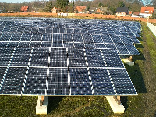
Advantages
- Cooler module temperature
- PV modules can get extremely hot during daytime due to the excessive heat generated from the modules and the ambient temperature. The best way to cool down the modules is natural convection using air, which is easily done when modules are elevated from the ground or roof so that air can carry out the heat and cool down the modules.
- Safe installation (no climbing required)
- Easy access for maintenance/troubleshooting
- No roof penetration/liability
- Flexible positioning for max production (potential use for single axis tracking). Ground mount is usually not restricted to be positioned at a certain tilt angle. That said, it is easier to choose the optimum tilt for maximum production.
Disadvantages
- Easy access (theft, vandalism, damage)
- Requires earth construction work (concrete, foundation, trenching)
- Space requirement
- Inter-row shading considerations
- PV modules can shade one another when installed in rows. For example, the first row can shade the second row located behind it. For more information, please refer to the video (6:08) explanation below from EME 810 [5].
Video: Shading Array Demo 1 - EME 810 (6:08)
So here we have the scenario of an array of photovoltaic that are set up one row behind the next. They're each going to have a certain tilt. That tilt is represented by beta and each one is going to have a common collector azimuth of gamma, represented down here. And that gamma again, is that plane or rotation. In this case, the array that you're seeing is rotated 9 degrees towards the east. So minus 9 degrees of rotation or 9 minus 180 degrees to give us our azimuth.
The distance between the panels, right now it's just specified as D. And the panels themselves are going to have a shadow. And that shadow is going to change over the course of the year, as the sun is high in the sky, and low in the sky.
And what we'd really like is for these panels to be spaced appropriately. Such that, they do not block each other. Because this is one of our goals, one of our mechanisms for the goal of solar design. You want to maximize the solar utility for the client or stakeholders in a given locale. And in this locale, want to know how far apart we can space these to collect the energy to basically avoid, or remove shading from the spacing of these panels.
So what you're seeing is a system that we're going to define in terms of critical points. We're going to take those critical points, and we're going to plot them on a diagram. So the first thing is, how do we list these critical points. Well now we don't have a central point X.
Now we actually have three points for each one of the panels across the top and across the bottom. This guy is going to be behind here, you won't see it. But you're going to have three points along the bottom, three points along the top. The points along the top are ultimately going to shade these critical points along the bottom.
So I'm going to name these critical points A, B, and C. And the points that we will be referring to in terms of what kind of shading are we expecting, we're going to label 1, 2, and 3.
So now going into this, you're looking at this from the side, and you're seeing a system like this, there's going to be a certain tilt beta. The beta is going to be the same for both collectors and they're going to be separated by a certain distance D. That's either going to be the spacing from top to top or from bottom to bottom, that's the same spacing with D.
So looking at this, we want to basically compare any point 1. And what we really like to see is, how does 1 compare to point C, point C is down here. One to point C, 1 to point B, and 1 to point A. That's one of our first questions.
And then after we've done that, we're going to look at how this point 2 compares to critical point C, critical point B, and A. And then we'll finally finish that with 3 C, 3 B, and 3 A. And what we should be able to see is that because of similar geometries we're going to find some kind of similar responses, in terms of all of these geometric relationships.
And I can show you that, again this is in the textbook, but if I bring this up right here, you're going to see that I've got a table of points 1.A, 2.A, 3.A, just like what we were talking about. And 1.B, 2.B, 3.B, 1.C, 2.C, 3.C. They each have their own set of altitude angles and you're going to notice that there are certain 21 degree common altitude angles. Just due to common geometries. Similarly, you're going to see common 41 degree angles and two 12 degree angles.
Looking at the azimuth angles, the 0 degree azimuth corresponds to 180 degree in the meteorological standard, and so on down. So we're seeing that 76 degrees is equivalent to 250 degrees. And minus 64 degrees is equivalent to 116 degrees.
So we're going to take these points this 180, 244, 256 for the azimuth angles of the collector. And we're going to plot those in the next block, and we'll plot the alpha angles. And what we're going to come up with is basically something that looks like the cross section of a loaf of bread. It's going to have two vertical sides and it's going to have an arch in the middle.
Pole Mount
This structure is common in public areas where the system is space constrained, as seen in Figure 5.2.
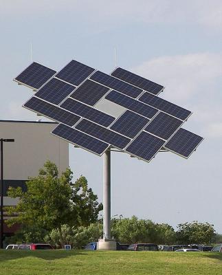
Advantages
- Cooler module temperature
- PV modules can get extremely hot during daytime due to the excessive heat generated from the modules and the ambient temperature. The best way to cool down the modules is the natural convection using air, which is easily done when modules are elevated from the ground or roof so that air can carry out the heat and cool down the modules.
- Easy access for maintenance/troubleshooting
- No roof penetration/liability
- Flexible positioning for max production
- Easy to adjust the tilt angle (potential use for dual axis tracking)
- Small footprint (one pole)
Disadvantages
- Easy access (theft, vandalism, damage)
- Requires construction (concrete, steel, foundation, trenching)
Note:
Single and Dual axis tracking systems are discussed in detail in EME 812 (3.3. Types of tracking systems) [1] and EME 812 (3.4. Engineered devices for solar tracking) [2]
Roof Mount (without roof penetration)
There are various types of roof mounts that don’t require roof penetration especially when the roof is flat, as illustrated in Figure 5.3. Of these types, ballasted roof mount is one of the most used racking structure for PV systems installed on flat roofs. It utilizes the weight of concrete or sand to ensure the system stays still to stand all kinds of external forces such as pullout wind forces.
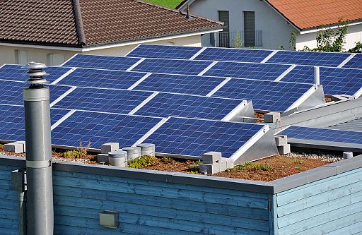
Advantages
- Low material cost
- Utilizes unused spaces
- Provides secure access for authorized individuals only
- Flexible positioning for ideal production
- No roof penetration needed
Disadvantage
- May require structural engineering and/or roof reinforcement due to added weight
Roof mount (with roof penetration)
These mounting structures allow the system to be installed parallel to the roof for the best esthetic solution for pitched roofs, as seen in Figure 5.4.
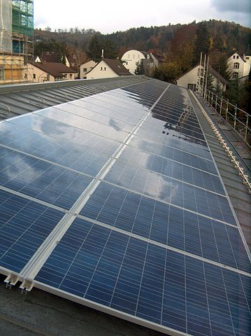
Advantages
- Lower material cost
- Utilizes unused spaces
- In most buildings, the roof is considered unused space. PV array can occupy these spaces and transfer them to useful spaces that can generate electricity for the building.
- Provides secure access for authorized individuals only
Disadvantages
- Requires roof penetration (roof leak liability or roof damage)
- Requires professional installers
- Higher module temperature (poor ventilation)
- PV modules can get extremely hot during daytime due to the excessive heat generated from the modules and the ambient temperature. Since PV modules cannot be elevated from the roof for more than a couple of inches, air movement is restricted from carrying out the heat to cool down the modules.
- Difficult conduit runs
- Most roofs have different gable shapes and sizes. In addition, the main electrical panel is usually located at the bottom of the building. That said, the PV array conduits have to run through the roof to the main panel and that route can be wiggly and require more attention to the details when installing the system.
- Fixed title and orientation
- Most roofs come with single pitch that cannot be changed. When a PV array is installed on the roof, the orientation and tilt are restricted by the roof pitch and orientation, and that might affect the production of the PV system.
- Pullout forces
- Wind speed flowing against the PV modules on the roof can cause forces that act similarly to pullout forces that try to remove the modules from the roof. That said, PV designers should ensure that the PV array is securely fastened to the roof using the right attachment mechanisms, such as screws and hooks.
Considerations
- Roof age
- Roof age is a critical factor to installing a PV array. A weak and old roof may not be able to withstand the added weight from the PV array.
- Snow and wind loading
- Snow and wind can add weight to the roof. If the roof is not designed to carry that additional weight, the roof might collapse.
- Fire issues
- When PV arrays are installed on roofs, installers should work with the local fire department to ensure that there are no fire hazards or accessibility issues if fire occurs.
There are other mounting types that are beyond our discussion for this class and students are encouraged to look for different racking structures for their own benefit.
For Further Reading
For more information about the mounting structures of the PV system, please refer to your Required Reading: Chapter 10 from the Dunlop text. Please note that some information in the reading chapter is not directly related to this topic; however, students are encouraged to read through the chapter for their own benefit.
Mechanical BOS Components
After reviewing different types of PV mounting structures, it is time to discuss the components that form these mounting structures. In this section, we will focus on the mechanical BOS components that help assemble the PV system components. These mechanical BOS components include fasteners, brackets, enclosures, racks, and other components that support the structure of the PV system.
Starting at the PV Array
PV modules need to be securely fastened to the racking structure, and that is done through rails, splices and clamps.
Rails
PV modules cannot be directly fastened to the roof of the building, for example. They require a structure that holds modules together that is later fastened to the roof or the ground. This structure is made of what is referred to as rails, which are rated to withstand heavy weights. Rails come in different shapes, profiles, lengths, and materials. Since rails manufacturers don’t make every desired possible length, the rails are tailored to fit each specific PV system.
Splices
When the PV system requires longer spans than the default length of the rails, splices are used to extend and connect rails to each other. Splices are usually provided by the same rail manufacturers.
Clamps
In order for the PV modules to be fastened to the rails, clamps are usually used to secure the connection between the rails and the modules. PV modules are usually installed adjacent to one another. As a result, some modules will be located in the middle and other modules will be installed on the edges. In this case, the middle modules will require what is referred to as mid-clamps to fasten the modules to each other and to the rails and end-clamps at the edge modules to lock the ends of the array.
Moving Away From the Rails
The rails need to be fastened to the mounting structure. This usually depends on the mounting type that can be roof mount, ground mount, or pole mount structures.
Roof mount (rooftop with penetration)
In case the PV system is installed on rooftops, designers should consider elevating the rails a couple of inches against the roof to allow for ventilation and lower temperature operating ranges. For that reason, there are multiple solutions in the solar industry to achieve that clearance. The rails can be fastened to the roof using one of the following options:
L-foot
L-foot utilizes screws that are fastened to the rafters or trusses from one side, and the other side will be attached to the rails. L-foot can be directly used to allow some roof ventilation; however, when the L-foot is not long enough to satisfy the ventilation requirements, Stand-offs are usually used to elevate the rails above the roof to allow proper ventilation to meet the design criteria. Stand-offs come in different lengths, and designers choose the best length based on the application and ambient temperature.
Tile Hooks
Roofs come in different shapes and materials. In the case of ceramic tile roofs, roof tile hooks can be directly used as roof attachment equipment that allows the rails to be fastened to the roof by going underneath the tiles. Tile hooks provide roof ventilation, as they are designed to be elevated from the tiles.
Roof Mount (without roof penetration)
PV systems can use S-5 clips or applied weight (i.e., sand or concrete) to fasten the rails to the roof. Let's elaborate on each type:
S-5 clips
In order for a PV array to be fastened to a metal roof (flat or tilted), manufacturers have developed solutions to allow rooftop installation without roof penetration. This solution includes an innovative clip that is called "S-5" and bites from one side of the metal roof. The other side will be fastened to the rails of the PV array. This solution minimizes the use of equipment grounding since the frame metals are directly connected to a metal structure. Designers should consult with the manufacturer's recommendations for grounding requirements when using these clips.
Applied Weight
Another solution to allow rooftop installation without roof penetration and is done using weight that holds the array to the roof. The applied weight can utilize sand or concrete, based on the design. Designers should take into account the roof age and the maximum allowed weight of the roof in order to accommodate the additional weight of the PV array. In some cases, the PV array's structural design needs to be reviewed by Professional Structural Engineers to ensure the structure can handle the additional weight.
Ground mount/Pole Mount
Reinforced concrete bases are usually used for ground and pole mount systems, with steel structure attached to the rails. In some cases, the PV array's structural design needs to be reviewed by Professional Engineers to ensure the structure can withstand dynamic loads based on the location and wind speed.
Note:
Racking structure load calculations are usually provided by the manufacturers in the specification datasheets. There are main parameters such as dead load, live load, wind load, and snow loads that contribute to the total weight of the PV array. These loads should be taken into account when calculating the weight per unit area that is usually referred to as Pound per Square Foot (PSF), or the concentrated Point PSF, and finally, the pullout force (uplift) that is directly related to the wind factor and how they might affect the panels.
For further reading:
For more information about the mechanical and structural load calculations, please refer to your Required Reading: Chapter 10 from the Dunlop text.
Electrical BOS components
The main goal of the PV system is to deliver the energy generated from the sun to the load or the grid, depending on the application. This cannot be achieved without the use of complementary components to allow the current to pass through the circuit. There are multiple electrical BOS components such as conductors, conduits, combiner boxes, protection devices, disconnects, grounding conductors, monitoring devices, and other electrical needed components. These components should be chosen to minimize electrical system losses, and at the same time, to withstand the operating conditions.
In this section, we will focus on the electrical BOS components and their functions as part of the PV system.
In the Electricity Basics section (before we began the course), we learned that conductors are needed to allow current to flow in the circuit. Since we have DC and AC circuits in the PV system and outdoor and indoor installation, we need to consider different properties for each conductor we choose.
Conductors
The conductor insulation should be rated to withstand high temperature and sunlight, since modules are installed outdoors. The main goal is to protect the bare conductor from coming into contact with personnel or equipment.
There are two types of wiring for PV circuits.
1: PV source-circuit wiring
This refers to the wires connecting the PV modules all the way to the combiner box, where stringing of modules are combined. These wires are usually located outdoors and are exposed to UV sunlight, extremely high temperature (90℃ or 194℉), and in some cases, they are exposed to moisture. Examples of insulation types recommended for these installations include USE-2 and PV WIRE.
2: PV output-circuit wiring
This refers to the wires passing through conduits, and they connect the combiner box with the DC disconnect. These cables are still installed outdoors, but they don’t have to be rated to withstand the same extreme conditions that the PV source-circuit wiring experiences. Due to costs associated with PV source-circuit wiring, it is recommended to transition to lower rated wires such as RHW-2, THW-2, THWN-2, and XHHW-2 that still need to withstand the same high temperature without having to be sun resistant.
Interior wires:
When wires enter a space or a temperature controlled environment, it is better to transition to NM, NM-B, or UF types. It should be noted that all interior conductors need to be in metal conduits or enclosures and rated to withstand fire.
Battery wires:
These wires are rated to withstand moisture and must be listed for hard-service use. It is also recommended to have them flexible for easier use. USE, RHW, and THW are commonly used types for battery wiring.
Note:
Please refer to your Required Reading: Chapter 10 from the Dunlop text for more details about insulator types, definitions, and their usages.
PV Wires
Most modern PV modules come with wires that connect the semiconductor terminals to the outer circuit. This allows current to follow to loads through a protective enclosure, located on the back of the PV module, called the junction box, as illustrated in Figure 5.5. As we can see, the junction box is the interface between the module and the wires. It consists of an outdoor rated plastic box, bypass diodes, and screw terminals for the wires. The junction box is also rated for outdoor operating conditions and must be weather sealed to prevent dust and moisture from building up.
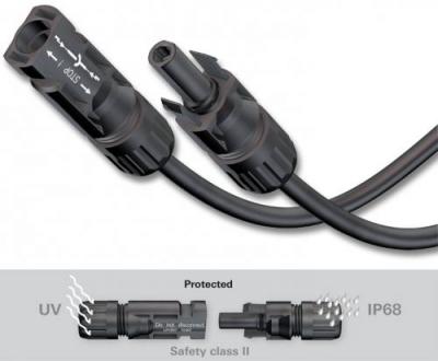
The wires coming out of the junction box are rated for outdoor conditions. Usually, they come with secured terminals, also known as module connectors, such as MC4, as shown in Figure 5.6. We can see that these plugs are weather sealed and also provide safety measures.
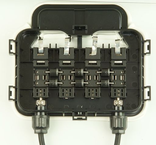
Combiner Box
The second main electrical BOS is the combiner box, which combines multiple PV strings into single circuit, as seen in Figure 5.7. Combiner boxes should be rated for outdoor applications and should withstand extreme weather conditions. There are usually screw terminals that apply compression force to secure wire terminals and ensure low resistance at the connection points, inside the combiner box. Lugs can be also used with compression force at the wire terminal. Lugs can have a ring or fork shape to make connections look much cleaner and to make them easier to manage. Protection devices such as Fuses can also be installed inside the combiner box for protection purposes.
Disconnects
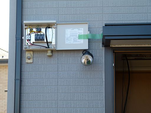
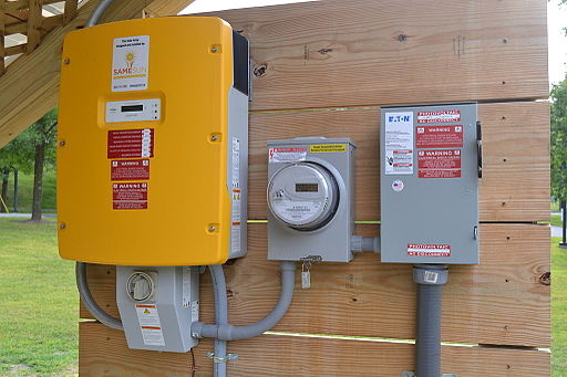
At the entrance and exit of the power conditioning unit, we need to be able to disconnect the current for maintenance work or commissioning procedure. That is usually done using DC disconnect and AC disconnect. In some cases, either or both DC and AC disconnect come as part of the inverter in a built-in device, as shown in Figure 5.8. It can be seen that the inverter has a box attached to the bottom of it with a hand switch that represents the disconnects. In both cases, disconnects need to be rated for the extreme outdoor weather conditions. DC disconnected can also have protection devices such as Fuses or Overcurrent Protection Devices (OCPD). We can also see in Figure 5.8 that the utility requires a separate AC disconnect after the utility meter. This disconnect is a manual lever handle type.
Conduits
Conductors are better protected if they are run through conduits, raceways, and wireways for damage protection and safety precautions. As can be also seen in Figure 5.8, all conductors between the combiner box and the utility disconnects are usually run through conduits.
Conduits can be made of different material types, including:
Metal
- Rigid metal conduit (RMC) is a thick-walled threaded tubing, usually made of coated steel, stainless steel or aluminum.
- Electrical metallic tubing (EMT), sometimes called thin-wall, is commonly used instead of galvanized rigid conduit (GRC), as it is less costly and lighter than GRC.
- Intermediate metal conduit (IMC) is a steel tubing heavier than EMT but lighter than RMC.
Non-Metal
- PVC conduit is the lightest in weight compared to other conduit materials, and usually lower in cost.
- Rigid nonmetallic conduit (RNC) is a non-metallic, unthreaded smooth-walled tubing.
- Electrical nonmetallic tubing (ENT) is a thin-walled, corrugated tubing that is moisture-resistant and flame retardant.
Note:
Other conduits types and their selection and installation are regulated by the National Electrical Code (NEC) and building codes.
Grounding conductors
PV systems need to be grounded to protect people and equipment from electrical hazard and equipment damage. The equipment grounding conductors (EGC) and grounding electrode conductors (GEC) and rods are considered part of the electrical BOS. In special cases, PV systems need to be protected from lightning. That is also done through a special grounding electrode connected to the ground in order to drain the lightning current.
Note:
Your Required Reading: Chapter 11 from the Dunlop text covers the electrical components of the PV system in more detail.
Lesson 5 Activity
| Activity | Details |
|---|---|
| Assignment |
Scenario 1Assume you are designing a system with the same module counts on the rooftop as shown in the video shown below. The Module used is Trina Solar Allmax 60 cell multicrystaline [16]. You may choose the SOLARMOUNT rail based options that can serve the purpose from Unirac (a racking manufacturer) [17]. You have standard 12” spaced rafters for a residential roof. Video: How Solar Works SSI (0:58)How Solar Works SSI
Click for text description of How Solar Works
As shown in the video, a solar array can be installed on a rooftop for residential application. After all mechanical holding structures are installed on the roof, the solar panels can be fastened to it . When the sun shines on PV panels, photons are converted into electrons that form electrical current when it moves towards the circuit terminals . The electrical DC current then travels through conduits down towards a power conditioning unit (AKA inverter) . The current is converted to AC electrical current and travels through an AC disconnect box . When the AC current exits the disconnect box, it goes through a PV production meter to count energy generated . After that, the current is back fed to the lower side of the Main distribution panel (MDP), where all load circuits are connected, through a protection breaker . When the PV array is generating power, the load circuits draw power from the PV array instead of the grid . While the PV array is generating power, the monitoring device is transmitting the data to an online portfolio, where clients can see their instantaneous PV array performance online . Finally, the excess energy generated from the PV array is returned to the utility grid . Credit: Sam Fortune
Scenario 2Assuming the roof is flat, the installation to flat roof with ballasted system from Unirac [18], taking the average cement weight of 32 lb. and considering the following:
DeliverablePrepare a report that includes your findings for each of the scenarios. The report should be no more than one double-spaced page in a 12 point font. |
| Submission Instructions and Grading | Please visit the Lesson Activity [20] page for submission instructions and grading information. |
Procurement Report/Peer Review
This week, you will complete the Peer Review portion of the Procurement Report assignment.
| Activity | Details |
|---|---|
| Assignment | Visit the Procurement Report/Peer Review [21] page for details of the overall assignment and submission instructions. This week, you will be working on and submitting the Peer Review. For the Peer Review portion of this assignment, you must complete the following:
|
Summary and Final Tasks
Wrapping up the trade show scenario we started, by now you can define and choose all types of mounting structures whether they are roof mount, pole mount, or ground mount system. You can also choose the required mechanical and electrical BOS for a perfect PV design and run the required load calculations for the racking structure based on the manufacturer's datasheets.
Whether you work for a solar firm or your own business, you can easily make the best selection of components for the entire PV system. Furthermore, you can suggest the optimal solutions for each PV system type based on the properties of the location of the system.
In the next lesson, we will take a detour to visit one of the main concepts when we design PV systems, which is system sizing for both grid-connected and stand-alone PV applications.
Reminder - Complete all of the Lesson Requirements!
You have reached the end of this lesson. Before you move to the next lesson, double-check the list on the first page of the lesson to make sure you have completed all of the requirements listed there.