Lesson 8: Applicable NEC Articles for Sizing Electrical Components of PV System and Grounding Requirements
Overview
Lesson 8 Scenario
Assuming the client, for whom you designed the interactive PV system in Lesson 6, closed the deal with the solar firm you work for. The next day, the design manager asks for the actual PV system design and documentation to be prepared. You happen to be a new employee with a good electrical engineering design background. However, your background is not directly related to PV systems. As you are familiarizing yourself with the PV electrical design process, you receive a call from the manager saying you are assigned a new project that requires electrical design to comply with the local codes. Fortunately, the NEC is adopted by the AHJ at the place where the system will be installed.
You previously learned that International Solar Energy Provisions adopted the NEC articles that relate to PV systems. So your first task is to understand and interpret the PV terminologies on the NEC and then interpret the articles that specify PV design requirements.
You noticed that NEC articles require an understanding of maximum voltage design, conductor ampacity and correction factors, voltage drop calculations, grounding and lightning, and the protection requirements.
In this lesson, we will train our PV designers to perfectly interpret the NEC articles that pertain to PV systems, and we will walk them through sizing and calculation processes to address the design issues mentioned earlier. Learning about NEC articles allows better understanding of the PV system as it integrates with other electrical systems. The knowledge available in this lesson is of interest to a wide range of audiences including designers, business owners, installers, or inspectors.
Learning Outcomes
At the successful completion of this lesson, students should be able to:
- Identify applicable fire and safety regulations affecting PV design and installation.
- Compare theories and practices for overcurrent protection and arc-fault protection.
- Calculate the voltage and current limits for various circuits of PV systems.
- Determine appropriate conductor ampacities and overcurrent protection ratings and types of conductors used for PV applications.
- Identify grounding requirements and electrical grounding methods.
What is due for Lesson 8?
Lesson 8 will take us one week to complete. Please refer to the Calendar in Canvas for specific time frames and due dates. Specific directions for the assignments below can be found within this lesson and/or in Canvas.
Complete the following Lesson Assignments:
- Read through the Lesson Content
- Complete the Required Reading Assignments:
- Chapter 11, Photovoltaic Systems by James P. Dunlop (text)
- Look over the Recommended Reading:
- Solar ABCs Expedited Permit Process Report - Revision 2 [1]
- Chapter 6: Solar Power System Design, Large‑Scale Solar Power System Design: An Engineering Guide for Grid-Connected Solar Power Generation by Peter Gevorkian [2] (pages 185-229) (*Penn State Login Required)
- Begin working on PV System Electrical Design Project
- Take the Lesson 8 Quiz in Canvas
*Students who register for this Penn State course gain access to assignments, all readings, and instructor feedback, and earn academic credit. Information about registering for this Penn State course is available through the Renewable Energy and Sustainability Systems Online Masters and Graduate Certificate Programs Office (link is external) [3].
Questions?
If you have lesson specific questions, please feel free to post to the Lesson 8 Questions discussion forum in Canvas. While you are there, feel free to post your own responses if you, too, are able to help a classmate with a question. If you have questions about the overall course or wish to share and discuss any "extra" course related commentary (interesting articles, etc.), please feel free to post to the General Questions and Discussion forum.
NEC and PV related terminologies
We learned in the previous lesson the importance of the electrical codes, and of the NEC in specific, to govern PV design and installation processes. NEC articles cover installation regulations for all PV installations including systems with less than 50V, utility-interactive systems, and stand-alone systems including billboards, remote installations, and RVs.
Terminologies
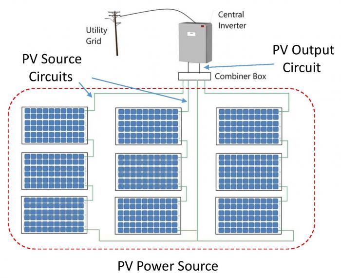
There are specific terms used for PV system components and circuits. The NEC differentiates between a PV power source and a PV source circuit for PV systems.
A PV power source is an array or collection of arrays that generates DC power.
A PV source circuit is the circuit connecting a group of modules together and to the common connection point of the DC system. PV source circuits are usually a string of series-connected modules. For small systems, the PV power source is usually only one source circuit. For larger systems, the PV power source is usually composed of several paralleled PV source circuits.
A PV output circuit is the circuit connecting the PV power source to the rest of the system.
Figure 8.1 illustrates the proper use of these terminologies and how they relate to each other in the PV system. The three strings of nine total PV modules that form an array are referred to as a PV power source, while each string of three PV modules is referred to as a PV Source Circuit. In this case, the PV system has three PV Source Circuits. As the conductors exit the PV array and are joined together in a combiner box, they form a single power source that links the inverter with the combiner box at the DC side of the PV. This is the PV Output Circuit.
Voltage design
As we learned earlier in previous lessons, the maximum possible voltage is the array’s open-circuit voltage measured at the lowest expected temperature for the specific location (the lowest record temperature). There are two main methods for PV professionals to determine the maximum voltage of a PV array.
Method 1
As we learned in Lesson 2, the voltage can be calculated using the PV module manufacturer’s temperature coefficient for voltage. Temperature information is usually gathered from weather stations for each location.
Method 2
The voltage can be easily identified using an NEC correction table, depending on the ambient temperature ranges of the location. The NEC provides a temperature correction factor found in table 690.7. The factors of the NEC table make calculations for estimating the maximum voltage as easy as multiplying the string voltage by a single number.
Example
Assuming you have a PV system with the following specification:
- There are 10 modules in series that form a PV string.
- The individual PV module open circuit voltage is 38V and the temperature voltage coefficient is 0.0032V/℃.
- The lowest ambient temperature is -10℉.
Then the maximum voltage according to method 1 can be calculated as follows:
We can find the Tcell to be -23°C at very low irradiance or in other words, . We can apply equations from Lesson 2.
The maximum module’s voltage will be:
Then the maximum voltage of the string will be:
The maximum voltage according to method 2 can be calculated as follows:
Looking up the voltage correction factor corresponding to -10℉, the factor is 1.20 (found on NEC table 690.7).
The maximum voltage in this case is
Reflection
We can see that both methods gave results with increased voltage by a factor. However, these factors are not equal. What value should a Pv designer use when designing a PV string for maximum voltage.
ANSWER: The NEC table method is more conservative and easy to use without tedious mathematical calculations. Designers usually use NEC values to ensure code compliance. However, educated designers are encouraged to argue their calculations with utility design reviewers when they use precise calculations based on actual weather values and a PV manufacturer's datasheet for voltage coefficients.
Conductor/Wire sizing
Conductor Sizes
Conductor sizes are expressed in American Wire Gauge (AWG). Usually, larger diameter conductors have smaller AWG numbers. There are two types of conductors, either solid or stranded. Solid conductors consist of one solid core metal conductor that is usually ridged. On the other hand, stranded conductors consist of multiple smaller conductors stranded together and are usually more flexible. Stranded conductors are ideal for PV source circuits, facilitating module removal for servicing, or junction box access.
Reflection
Since larger conductors have greater current-carrying capacity, are they stranded or solid?
ANSWER: Larger conductors can be stiff and difficult to work with during installation. Therefore, larger conductors are stranded, which makes them more flexible.
Note:
Conductor sizes and corresponding diameters, area, and resistance can be found in NEC Chapter 9 on Table 8. You can also review the reprinted version in Chapter 11 of the textbook.
Conductor Ampacity
Conductor sizing is based on a conductor’s ampacity rating.
Ampacity is the current that a conductor can carry continuously under the conditions of use without exceeding its temperature rating.
According to the NEC, nominal conductor ampacity at 30°C is determined by the conductor material (copper or aluminum), size, insulation type, and application (direct burial, conduit, or free air). In NEC, table 310.15(B)(16) (formerly 310.16) is used to look up the ampacity rating for any conductor.
Ambient Temperature Derating
Temperature affects conductor’s ampacity; nominal ampacity is derated (reduced) when ambient temperature is higher than the nominal 30°C. Temperature-based ampacity correction factors can be found in NEC table 310.15(B)(2)(a). The correction factor is then multiplied by the nominal ampacity (found in table 310.15(B)(16) to calculate the derated ampacity. Therefore, for a certain current-carrying capacity rating, the size of the required conductor must be increased to account for higher temperature deratings.
Number of Conductors Derating
Since most PV systems consist of multiple PV source circuits that run to the combiner box, more than three current-carrying conductors can be run together in a conduit or a raceway for longer than 24′′. In this case, conductor ampacities must be further derated by an additional correction factor that can be applied to the temperature-corrected ampacity using NEC table 310.15(B)(3)(a), where designers can look up the corresponding ampacity correction factor based on the number of current-carrying conductors.
Reflection
Why is it needed to derate the ampacity when more than three current-carrying conductors are installed together?
ANSWER: Because bundling several current-carrying conductors together affects their ability to dissipate heat.
For example, if USE-2 conductors are used for three PV source circuits and are run through a conduit, each with positive and negative conductors, the total is six current-carrying conductors. The correction factor from the NEC table is 0.80.
Note:
The neutral conductor in a three-phase AC system is not considered a current-carrying conductor. We touched base on the conductor's insulators on the electricity basics in the orientation of this class, and we noticed that insulators can be different in types and materials. As a recap, insulation protects the bare conductor from coming into contact with personnel or equipment. Conductor insulation types used in PV systems must be compatible with the environmental conditions and ratings of the associated equipment, connectors, or terminals.
Reflection
What are the properties of insulating material for a conductor?
ANSWER:
- Maximum operating temperature,
- Application and Environmental resistance (such as to sunlight, oil, or moisture),
- Permissible installation locations (such as direct burial, in conduit, or exposed).
PV module electrical connections are usually installed with full exposure to extreme temperature, sunlight (UV), and precipitation. PV conductors need to be rated for outdoor applications with high temperature, moisture, and sunlight resistance. Insulation types UF, SE, USE, and USE-2 are permitted in PV source circuits, provided they have the necessary weather resistances. Single-conductor USE-2 is recommended because it has high temperature, moisture-resistance, and sunlight-resistance ratings, and is widely available. In the NEC, table 310.15(B)(2)(c) is used for ambient temperature increment due to conduits being exposed to sunlight on or above rooftops.
Conductors and color codes
Since a PV system is a mixture of both AC and DC systems, conductor color codes are similar to any other electrical system with each side of the system. For example, when we look at the DC side of the PV array, we should consider applying the DC color code. Once we exit the inverter, the color code of conductors should comply with the AC color code of electrical systems. Below are main considerations for the color codes of conductors.
- Grounded conductor must be white, gray or have three stripes, not green.
- Module frame ground must be bare or have green or green with striped insulation or identification.
- Grounded conductor is the negative conductor (white). No NEC requirement for ungrounded conductor. Use AC convention Black and Red.
- In two wire negative-grounded PV system, the positive conductor could be red or any color with red marking, except green or white.
- In a three-wire, center-tapped system, Positive conductor Red, center tap conductor must be white, and the negative conductor could be black
Note:
NEC articles 250.119 article 200.6(A)(2) are used to find the conductor color codes.
PV Circuit Current Requirements (sizing, protection)
As instructed in NEC 690.8 Circuit Sizing and Current, the wires from the PV modules to the inverter must be able to carry 156% of the short circuit current (Isc). This 156% comes from multiplying 125% twice; the first 125% accounts for the continuous duty that is used as a safety factor, whereas the second 125% is a factor that accounts for the extra current that PV modules might deliver. This current, that is higher than the rated short-circuit current of PV modules, can be generated when the solar irradiance exceeds 1000 W/m2. Therefore, the maximum output current is derated by a factor of 125% x 125% or 156%.
Circuit current is the sum of the parallel source circuit's maximum current, as calculated in 690.8(A)(1). This applies mostly for central inverter configuration.
PV Source Current [690.8(B)]
The maximum PV source circuit current is 125% in addition to 125% of the short circuit current. In our example, if a PV module has Isc of 8.60 A
Conductor Sizing [690.8(B)(1)]
Conductor size is chosen to be the smallest size that can safely conduct the maximum conductor current of a circuit (Imax). As discussed previously, the maximum current that the PV system can generate is 156% of Isc. That means the conductor must carry this amount of current.
Voltage Drop
Definitions
Voltage drop is defined as the amount of voltage loss that occurs through all or part of a circuit due to conductor resistance.
Conductor resistance is determined by conductor material, size, and ambient temperature.
Voltage drop highly depends on the total length of conductors that carry the electrical current. In DC systems, the voltage drop length is the total (round-trip) distance that current travels in a circuit. So the total length used in calculations is usually twice the length of the conductor run. In some AC systems, the distance equals the length of the conductor.
Reflection
Why is the conductor length different for AC and DC circuits?
ANSWER: Since the current flows constantly in DC circuits, the current will travel back and forth. In this case, the distance is twice the length of a conductor. The same applies to two-wires single phase (120V in the USA or 220 in Europe), the AC Voltage Drop is calculated in the same way in which the distance is twice the length of the wire. (to account for the Phase and the Neutral wire lengths as the current travels back and forth through them).
- In the three-wires single phase (AKA split-phase in the USA), the voltage is still 120V between the phase and the neutral, but the current doesn't travel back through the Neutral wire. This is a result of the nature of the phases being split (with180 degree phase shifted) so the Neutral wire only returns the imbalanced current. In a balanced load condition, the return current (through the Neutral wire) equals Zero.
- In the four-wires three phases systems, the same situation arises, as the Neutral is not supposed to return any current under balanced load conditions.
Since most single-phase PV inverters are rated at 240V, the Voltage Drop for split-phase is calculated as follows:
One can calculate the voltage drop using the two-way trip distance at 240V (the same equation used for DC circuit) but your voltage will be the phase-to-phase 240V instead of the 120V phase-to-neutral.
Voltage drop from PV array to inverter
NEC doesn’t require the calculation of voltage drop because it’s not a safety issue. However, it does recommend a maximum voltage drop of 3%. It is recommended to have up to 2% voltage drop at the DC side while only 1% is accepted at the AC side of the system for a total of 3% in voltage drop for the entire system.
Wires should be sized to reduce resistive (heating) loss to less than 3%. This loss is a function of the SQUARE of the current times the resistance, which is another manifestation of Ohm’s law:
And the resistive loss is in Watts.
Note:
Use a wire-sizing table to choose the right wire size for the current and voltage you are working with. Visit Encorewire.com [4] for an example.
Example
Computing the voltage drop formula:
Where:
is the circuit operating current, which for source circuits is usually taken as the maximum power current, Imp,
L is the total conductor length.
is the voltage at which you want to find VD, and
is the wire’s resistivity in Ohms per 1000 feet and is found from NEC Chapter 9, Table 8 conductor Properties.
Example
If we have a PV array that is located 150’ away from the inverter (L=150 ft) and we are using wire # 14 AWG since it handles the current of 8.23A, and it has resistivity of 3.14 (Ω/kft).
The operating Voltage is
The voltage drop then is calculated as:
, which is not within the limit of 2%, but this wire is running to a combiner box and to the inverter. In this case, the voltage drop should be less and the size of conductor must go up.
Upgrading to a larger conductor size for the same length and conductor type:
The voltage drop then is calculated as:
As can be seen, both conductors sizes # 12 and #14 work for ampacity, but the voltage drop calculation shows that both of them still not the best option for the long term. As a result, cable # 10 AWG is a more conservative design, but it will cost more.
Note:
There are some freely available tools that can be used for voltage drop calculation. This is an example of an Online Calculator. [5] If there is no DC option for the calculator, you can use single phase and choose the right length.
Protection Devices and Disconnects
Overcurrent Protection Devices (OCPD)
Overcurrent protection devices are classified by how quickly they activate. Overcurrent protection devices can include fuses and circuit breakers.
A non-current-limiting device operates slowly, allowing damaging short-circuit currents to build up to full values before opening. An example is a fuse, which is a link that melts when heated by current greater than its rating to provide overcurrent protection due to extra loading.
A current-limiting device opens the circuit in less than one-quarter cycle of short-circuit current, before the current reaches its highest value, limiting the amount of destructive energy allowed into the circuit.
Overcurrent protection devices must be listed and specifically rated for their intended use, such as DC. For example, automotive fuses may not be used in PV systems.
Sizing OCPD
OCPD are highly recommended for PV systems and are sized not to be less than the highest current.
- DC array side
- Since the derate factor is 156% of the short circuit current of the PV module, the OCDP is sized not to be less than that value, since the 125% factor is included already as part of the calculation.
- AC side
- At the output of the inverter, OCPD are usually sized to be at least 125% of the highest inverter current possible, provided from the manufacturer’s datasheet.
Disconnects
A disconnect must be provided to open all current-carrying conductors of a PV power source from all other conductors in a building or structure. This disconnect is also known as the DC disconnect or PV disconnect. Disconnects used in the PV output circuit must be rated for DC and identified as such. Equipment such as PV source-circuit isolating switches, overcurrent protection devices, and blocking diodes are permitted on the array side of the array disconnect.
Disconnects Sizing
-
DC array disconnect
-
Since the derate factor is 156% of the short circuit current of the PV module, the DC is sized not to be less than that value, since the 125% factor is included already as part of the calculation.
-
-
AC disconnect
-
At the output of the inverter, disconnects are usually sized to be at least 125% of the highest inverter current possible, provided from the manufacturer’s datasheet. In an interactive system, the PV system’s AC disconnect should be located near the main utility disconnect. This facilitates the quick removal of all power to a building or structure in an emergency.
In stand-alone systems, the AC disconnect is typically located near the array disconnect or the AC power distribution panel. Disconnects must be provided to open all ungrounded conductors to every additional power source and each piece of PV system equipment. Other equipment that requires disconnecting means can be inverters, charge controllers, and other major components. If equipment is connected to more than one power source, each power source must have a designated disconnecting means. It is particularly important for battery bank circuits to include a specific DC disconnect.
-
Grounding and lightning
Grounding
Grounding provides a path for fault current or lightning surges to flow through to protect people and equipment from electric shock hazards.
Equipment Grounding Conductor (EGC)
PV modules mounted to metal racks are effectively grounded when the module frames are secured to and in electrical contact with the rack, and the rack is grounded. However, since the integrity of the electrical contact between the module frames and mounting structure cannot always be assured, individual module frames are connected together with equipment grounding conductors (EGC). This can be accomplished with a few continuous runs of bare conductor that are secured to each module with a special connector, or with many short bonding jumpers between adjacent modules.
Note:
Some exceptions apply to mechanical WEEBS or similar devices that bite into the modules frame and the raking rails, and they are UL listed as grounding devices. In this case, equipment grounding conductors are not required.
When ground-fault protection is used, PV circuit equipment grounding conductors are sized in accordance with Article 250, which establishes the minimum size for equipment grounding conductors based on the overcurrent protection rating in the circuit. NEC table 250.122 is used for sizing. For example, if the PV output circuit overcurrent protection device is 60 A, then a 10 AWG equipment grounding conductor is required. When the sizes of ungrounded conductors are increased above what is required (such as to decrease voltage drop), the equipment grounding conductors must be increased proportionally.
Grounding Electrode Conductor (GEC)
A grounding electrode is a conductor rod, plate, or wire buried in the ground to provide a low-resistance connection to the earth. NEC 690.47 establishes requirements for grounding electrodes used for PV systems. Most PV systems involve both AC and DC systems, and they are considered two separate systems according to NEC article 690 since the DC grounded conductor is not directly connected to the AC grounded conductor.
Array Grounding
Some AHJ may require an interpretation of some NEC editions to include an array grounding in addition to the DC grounding requirements. It is a grounding electrode that is buried in the ground as well.
Note:
For more information about the grounding and lightning, you can refer to Chapter 11 in the textbook.
Ground fault protection
Ground Fault is the undesirable situation where the current flows through grounding conductors. Ground Fault Protection is mentioned in NEC 690.5 and is not required for ground mounted arrays. It is required for PV systems mounted on roofs of dwellings. The ground-fault circuit breaker trips when current between the grounded and grounding conductors exceeds its rating and forces the other circuit breaker to open the ungrounded conductor. For low-voltage PV systems, a pair of circuit breakers can be used to provide array ground-fault protection. For interactive PV systems, ground-fault protection is usually built into the inverter, which includes a serviceable fuse. In order to fulfill the requirement to open the ungrounded conductor, the inverter is designed to immediately shut down if the fuse is opened.
A ground-fault circuit interrupter (GFCI) is a device that opens the ungrounded and grounded conductors when a ground fault exceeds a certain amount, typically 4 mA to 6 mA. It does this by sensing a difference between the current flowing out through the ungrounded conductor and returning through the grounded conductor.
A GFCI device is used in AC branch circuits to protect persons from electrical shock hazards. GFCI protection is often included in receptacles and is required in wet environments, such as bathrooms, with a greater potential for ground faults. Article 210, “Branch Circuits,” provides details and required locations for GFCI devices.
Lightning protection
Because PV arrays are mounted on elevated buildings and structures such as rooftops and poles, many PV systems are protected from potential lightning that can cause severe damage. Lightning protection system requirements are covered briefly in Article 250 and more extensively in NFPA 780 (Standard for the Installation of Lightning Protection Systems). Lightning protection is especially important in places where the probability is high, such as the southeastern United States.
Lightning protection systems consist of a low-impedance network of air terminals (lightning rods) connected to a special grounding electrode system and not connected to the DC or array electrode conductors.
PV System Electrical Design Project
This week, you will begin working on your PV System Electrical Design Project. This will be a two-lesson project.
| Activity | Details |
|---|---|
| Assignment | This project will help our solar professionals gain skills in designing the electrical documents for PV systems. The project asks to develop a one-line electrical design of a PV system showing all related calculations and details to comply with NEC article 690. The project then puts you in three different scenarios that require you to evaluate the interconnection requirements, depending on the size and rating of the electrical service of the property. Visit the PV System Electrical Design Project [6] page for the complete details of this assignment. Note: You will not be submitting this project within this lesson. You will be submitting the entire project at the end of Lesson 9. |
Summary and Final Tasks
After discussing PV system main components, system sizing strategies, and building and fire codes that govern the design and installation of any PV system, our design team is ready to dig deeper into the essential electrical code NEC articles to start preparing the required engineering design permitting documents to submit to the utility grid engineering reviewers. This process requires a detailed NEC interpretation of article 690 and 705 and other code articles that pertain to PV systems, as we saw in this lesson.
By now, our design team is one step away from being granted the permit. That missing part is the interconnection requirements by the utility grid where the system will be installed.
In the next lesson, we will discuss the interconnection requirements and methods where they apply to PV systems, and we will talk about some issue related to the interconnection of PV systems such as neutral loading, phase balance, and metering. See you next week!
Reminder - Complete all of the Lesson Requirements!
You have reached the end of this lesson. Before you move to the next lesson, double-check the list on the first page of the lesson to make sure you have completed all of the requirements listed there.