2a.3 The Rotor Disk Model
Introduction
Our next step is to develop “The Rotor Disk Model” that allows for rotation of the actuator disk and the downstream wake. The following assumptions, though, remain:
- One-Dimensional
- Inviscid & Irrotational
- Steady
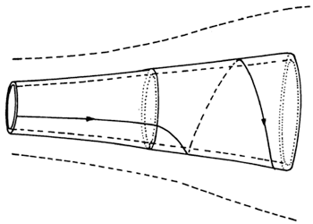
In the simplified model of a rotor disk, we still consider a streamtube, however we proceed one step towards an actual wind turbine rotor by adding a ‘swirl’ or ‘rotation’ to the wake. Without further analysis, we surmise that the addition of wake rotation to the flow inside the streamtube is associated with a loss in power produced by the rotor disk as additional kinetic energy is needed to sustain the rotation of the wake.
The actuator disk theory revealed that the maximum power coefficient CP is governed by the Betz limit of CP,max=0.59. We will find that adding wake rotation will decrease the theoretical maximum. – The actuator disk theory generated the rotor power via the rotor thrust and the axial induction factor a. In rotor disk theory, on the contrary, we will discover that rotor power is generated through rotor torque and the angular momentum in the wake via a combination of axial- and angular induction factors.
Transcript: Actuator Disk to Rotor Disk - Introduction of Wake Rotation
The Betz limit is the limit, 59% of the energy that we can capture from the wind. Now, if you allow the actuator disk to become a rotor disk that's spinning at some rotor speed omega, the side of effect of doing that is that you add a swirl to the downstream wind. Adding a swirl means you have to pay for it. You have to pay for it with momentum and energy. In other words, that side of effect of the method that makes you adding that swirl, is that you cannot capture as much energy as in the actuator disk model. So we will get something that is less than the Betz limit for sure. The question is how much is that.
Rotor Torque and Power
At first, let us recall from classical mechanics that rotor torque is associated with a change in wake angular momentum:
Rotor Torque = Change in Wake Angular Momentum
We denote the rotor speed or the angular velocity of the rotor disk by Ω (Omega). The wake speed, respectively, is the sum of the rotor speed Ω and the swirl speed ω (omega). We thus have:
Rotor Speed: Ω
Wake Speed: Ω + ω
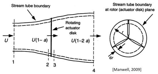
Next, we consider an annulus of width dr of the rotor disk and write the incremental torque dQ acting on the annulus as...
...where the term in brackets represents a mass moment of inertia flowing through the considered annulus of the rotor disk.
Transcript: Mass moment of inertia
The mass moment of inertial, you have to be careful. I cannot just take the entire disk to do it. Because the mass moment of inertia is something that changes with distance over mass to the center of rotation. So I take the ring or annulus out of that rotor disk and consider what will be the incremental torque distribution of that.
We make use of the definition of the mass flow rate in eqn. (2a.2) dm* = ρ · u · dA and write the incremental torque as:
We also remember from previous analysis that the velocity at the rotor disk is u = (1-a)·V0 , and note that an incremental area dA of a rotor disk annulus is dA = 2 πr · dr
We can also define an incremental power and an incremental power coefficient in the following way:
Rotor Torque and Power
Our next task is to find an expression for the incremental power coefficient d CP. Before proceeding, though, let us define some additional dimensionless parameters that will he helpful in the analysis and useful to a thorough understanding of the effects of wake rotation.
Angular Induction Factor: a' = ω / (2 Ω)
Tip Speed Ratio: λ = (Ω · R) / V0
Local Tip Speed Ratio: λr = λ · r/R
The ‘angular’ induction factor a’ is defined as being proportional to ω. It is apparent that in the special case of ω = 0 the angular induction factor becomes zero, and the rotor disk model reduces to the original actuator disk model. The next parameter, i.e. Tip Speed Ratio λ, involves the rotor speed Ω and describes the ratio of the blade tip speed Ω · R to the wind speed V0. We will see later in this course that typical values for λ range between 4 and 7. The third parameter shown is the Local Tip Speed Ratio λr, which is simply a fraction of λ based on the local blade position r/R.
Using these newly defined parameters and performing some algebra on the incremental power dP we obtain
...which gives us the incremental power dP as a function of wind speed V0, blade radius R, the rotational parameters λ and λr, and the dimensionless axial- and angular induction factors a and a’.
Hence, the differential power coefficient dCP becomes
Transcript: differential power coefficient dCp
The incremental power coefficient of an annulus on the rotor disk is a function of the tip speed ratio, the angular induction factor, the axial induction factor, and the local tip speed ratio, which is simply a product of the actual tip speed ratio times you local relative location along the blade.
The power coefficient CP of the wind turbine is obtained by integrating the previous equation along the entire rotor disk, specifically for λr ranging between 0 and the tip speed ratio λ.
As the integral for the power coefficient CP is performed over the local tip speed ratio λr, our next task is to find two relations between λr and the axial- and angular induction factors a and a’, which will enable us to compute the integral in (2a.27). We will do so by considering the following:
First, let us remember equation (2a.9) from actuator disk theory that related the pressure jump Δpa across the actuator disk to the axial induction factor a.
Actuator Disk: Δpa = ½ ρ (V02 - u12) = 2 ρ V02 a (1 - a)
What approach would we take for the Rotor Disk?
Our approach consists of having the same pressure jump cause the wake rotation ω. Hence, we are looking for Δpa’ = Δpa. In actuator disk theory, we used the Bernoulli equation applied to the axial velocity component through the streamtube.
We will use a similar approach here, however considering only the angular (or rotational) velocity. We write the Bernoulli equation as:
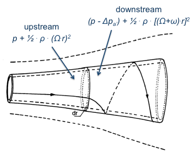
And substitute ω using the definition of the angular induction factor, i.e. a’ = ω / (2 Ω). Thus, we find for the pressure jump Δpa’:
Equating both formulations for the pressure drop across the rotor disk, i.e. Δpa = Δpa’ , we obtain the following after some algebra:
Transcript: First relationship between a and a'
And this omega times r/V0 square is again the square of the local tip speed ratio lambda r. So we isolate this on the right hand side and so on the left hand side you get the ratio of a(1-a) divided by a'(1+a').
The above equation constitutes a first relation between a, a’, and λr . In order to evaluate the integral for the power coefficient CP in (2a.27), we must find a second relation.
We mentioned earlier that the addition of wake rotation is likely to reduce the maximum power coefficient CP,max=0.59 due to Betz in actuator disk theory. One of our objectives in rotor disk theory is to understand to what extent do the newly introduced parameters a’, λ, and λr reduce the Betz limit. By inspecting the integrand in (2a.27) we realize that the maximum power coefficient occurs for the integrand factor a’(1-a) attaining a maximum for each λr. We therefore want to maximize the function f(a, a’) = a’(1-a). As a first step, let us compute the first and second derivatives of f(a,a’) using the product rule:
Next, we must perform the necessary algebra find the second relation between a and a'.