
Reading Assignment
- SECS, Chapter 6: paying attention to sections of "Collector-Sun Angles" and "A Comment on Optimal Tilt"
Once we have identified our specific location on the surface of Earth, and used those coordinates to identify the location of the Sun in the skydome relative to a fixed observer in a given locale, we can enter the angles for the orientation of our SECS. Again, this text closely complements the text in the book.
What is different here?
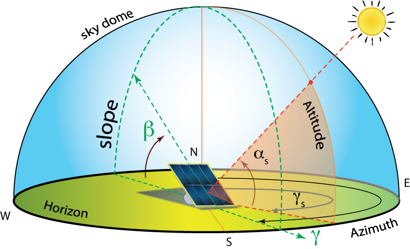
This new set of relations is for the general cases of any surface (horizontal or tilted, fixed or tracking). We are now describing angles for real oriented surfaces on Earth, like tilted PV panels and walls of a building. As we noted in the last section, for real SECSs, the receiving surface is tilted (beta, , with an azimuth orientation γ) to minimize the cosine projection effect that occurs at a given latitude.
Also, pay particular attention to the angle of incidence (theta with no subscript, ). As part of a solar energy design team, one of our primary mechanisms to increase the solar utility for the client in a given locale is to minimize the angle of incidence at a given time during the year or day. This is an extension or refinement of reducing the cosine projection effect.
Finally, I will give you a heads-up for the next page: after reviewing these sections and completing this page, you will need to take the Lesson 2 Quiz. Note that this is a quiz with calculations, and you will likely want to have a numerical software open to work through the numerical problems.
The following angles describe the orientation of the collector surface and the relation of the collector surface to the Sun. As these three angles describe our primary surface of interest, the SECS, they do not have a subscript for the two coordinate angles of collector tilt and collector azimuth.
- Tilt: the angle between the plane of the collector (or aperture) and the horizontal. Denoted by the symbol beta, β.
- Azimuth: the planar rotation East or West that an aperture will have. Denoted by the symbol gamma with no subscript, .
- Angle of Incidence: the angle between the vector perpendicular to the collector plane, called the normal of the plane, and the projection of the Sun’s central beam to the collector surface. Denoted as theta with no subscript ().
For general cases, where the collector has a non-horizontal orientation (), the angle of incidence is not the same as the zenith angle (θz). In fact, the zenith angle is a special case of an angle of incidence for horizontal surfaces, where the zenith is referenced to the aperture as a normal projection.
The first and second angles of tilt and surface azimuth (and γ) are typically known for fixed surfaces. The third key angle is the angle of incidence (θ), which uses the following rather lengthy equation:
In order to generate an actual value for theta, we will need to also take the arccosine of the long equation. For your calculators and math programs, all of the arguments are in terms of degrees, not radians. You will need to convert degrees to radians in most programs.
However, this is a really long equation that can actually be broken down into parts. We will break up the equation for the angle of incidence (theta, ) into three lines. Take a look at them, and look for common arguments to the sine and cosine functions.
- ( , , : latitude, declination, and tilt)
- ( , , , : latitude, declination, tilt, and then collector azimuth)
- ( , , , , : latitude, declination, tilt, collector azimuth, and then the hour angle)
Mechanisms to Maximize Solar Utility:
In the introduction of the textbook, there is a reference to the goal of solar energy design: to maximize the solar utility for a client in a given locale.
There are three main design mechanisms that will increase the solar utility of a SECS for a client or group of stakeholders.
- Decrease the cosine projection effect: This is done by tilting the collector toward the Sun's average annual noontime position. The higher the latitude of the locale, the more tilt a collector will need. Seasonal tilt changes can also slightly improve the solar gains. We also direct the collector toward the equator, although there is significant flexibility in both tilt and azimuth.
- Minimize the angle of incidence: This is a refinement of the first mechanism over the course of a given day, particularly relevant to solar tracking systems. By "pointing" the collector normal at the Sun during the day, the angle of incidence is minimized, and more light can be collected.
- Minimize or remove shading effects from the collector: We will cover this in the next few pages. It should make sense that when shadows cover a collector, then the majority of the Sun's light for that unexposed area is no longer providing power. Photovoltaics will be much more susceptible to shading issues than solar thermal systems, due to the near instantaneous generation of charge carriers in PV vs. the slower reaction from a thermal response of fluids.