
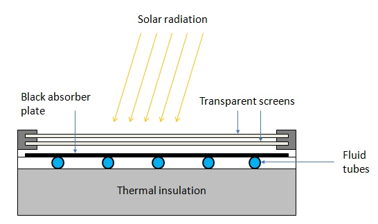
The flat-plate solar collectors are probably the most fundamental and most studied technology for solar-powered domestic hot water systems. The overall idea behind this technology is pretty simple. The Sun heats a dark flat surface, which collect as much energy as possible, and then the energy is transferred to water, air, or other fluid for further use.
These are the main components of a typical flat-plate solar collector:
- Black surface - absorbent of the incident solar energy
- Glazing cover - a transparent layer that transmits radiation to the absorber, but prevents radiative and convective heat loss from the surface
- Tubes containing heating fluid to transfer the heat from the collector
- Support structure to protect the components and hold them in place
- Insulation covering sides and bottom of the collector to reduce heat losses
The flat-plate systems normally operate and reach the maximum efficiency within the temperature range from 30 to 80 oC (Kalogirou, 2009), however, some new types of collectors that employ vacuum insulation can achieve higher temperatures (up to 100 oC). Due to the introduction of selective coatings, the stagnant fluid temperature in flat-plate collectors has been shown to reach 200 oC.
Probing question
- What are the typical materials used for absorber plates and glazing covers?
We partially discussed material choices and properties in Lesson 2. However, you are encouraged to look wider and review the current innovations in the flat-plate designs. For the discussion in this lesson, you will be asked to share what you found during your search and describe the state of the art materials that help increase collector performance.
Some advantages of the flat-plate collectors are that they are:
- Easy to manufacture
- Low cost
- Collect both beam and diffuse radiation
- Permanently fixed (no sophisticated positioning or tracking equipment is required)
- Little maintenance
Flat-plate collectors are installed facing the equator (i.e. South oriented in the Northern hemisphere and North oriented in the Southern hemisphere). The optimal tilt of the collector plate is close to the latitude of the location (+/- 15o). If the application is solar cooling, the optimum installation angle is Latitude - 10o, so that the solar beam is perpendicular to the collector during summertime. If the application is solar heating, the optimum installation angle is Latitude + 10o. It was found however, that for year-round hot water application, the optimum angle is Latitude + 5o, which provides somewhat better performance during winter, when the hot water is more needed (Kalogirou, 2009)
Transport fluid options
The flat plate collectors can involve liquid or air heat transport.
Water is one of the common options as liquid fluid due to its accessibility and good thermal properties:
- It has a relatively high volumetric heat capacity
- It is incompressible (or almost incompressible)
- It has a high mass density (which allows using small tubes and pipes for transport)
One disadvantage of water is that it freezes during winter, which can damage the collector or piping system. This can be managed by draining down the collector at low solar inputs (below a critical insolation threshold). Drain down sensors are often employed to monitor the system and to ensure complete draining, as pocket water freezing can cause damage. Refilling the system with water on the next morning also is not perfect. Possible air pockets in the collector can be a problem, blocking water flow and decreasing system efficiency (Vanek and Albright, 2008).
Antifreeze mixtures can be used instead of pure water to alleviate the above-said problems. The common antifreeze components are ethylene glycol or propylene glycol. Those chemicals are mixed with water require closed-loop systems and proper disposal due to toxicity. Nominal antifreeze service like is about 5 years, after which it needs to be replaced.
Air can be used as transport fluid in some designs of flat -plate collectors. This option is better suited to space heating applications or crop drying. A fan is usually required to facilitate air flow in the system and efficient heat transport. Certain designs can provide passive (no fan) movement of air due to thermal buoyancy.
Phase-change liquids can also be used with flat-plate collectors. Some refrigerants are included in this group of fluids. They do not freeze, which eliminates troubles explained above for water, and, due to their low boiling point can change from liquid to gas as temperature increases. Those fluids can be practical in settings where quick response to rapid temperature fluctuation is needed.
Collector construction
The key considerations in flat plate collector design are maximizing absorption, minimizing reflection and radiation losses, and effective heat transfer from the collector plate to the fluids. One of the important issues is obtaining a good thermal bond between the absorber plate and changes (tubes or ducts containing the heat-transfer fluids). Different construction designs (shown below) try to address this issue.
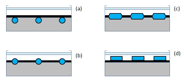
The plate - channel assembly may use a variety of methods of component attachment - thermal cement, solder, clips, clamps, brazing, mechanical pressure applicators. One of the considerations in choosing the assembly method is cost of labor and materials.
Next, we are going to look at the energy transfer and balance within the flat-plate collector.
References:
- Kalogirou, S.A., Solar Energy Engineering, Elsevier, 2009
- Vanek, F.M, and Albright, L.D., Energy Systems Engineering, McGraw Hill, 2008.