Lesson 3: Flat Plate Collector Systems
The links below provide an outline of the material for this lesson. Be sure to carefully read through the entire lesson befor returning to Canvas to submit your assignments.
3.0 Introduction
I take great pleasure in saying that after a thorough trial extending over a year and a half, our solar heater continues to give just as much satisfaction as when first installed. I am ready to admit that [at first] we were unreasonably prejudiced against the heater, and feel that refusing to let you install one in my house for so long a time after you first approached me upon the subject, we lost a great deal of comfort and convenience.— J.J. Backus
Los Angeles Superintendent of Buildings, 1907,
to the Climax Solar (Flat Plate) Water Heater.
Flat plate collector systems are a very robust technology. With no moving parts, the conversion of solar radiation to heat in a working fluid can be very reliable with simple heat exchanger technology and, essentially, plumbing. Some systems that are configured at higher pressures than what is near ambient pressure can be at risk for leaks at joints in and between the system components due to the pressure difference and, in general, system leaks are the most common mode of failure. Performance and efficiency of various collectors, collector types, and system types can impact capital and operating costs that would be different in different locations based on climate and the subsequent energy losses associated with different technologies in different environments.
Learning Objectives
- Recognize the main components and layers of flat plate collectors.
- Define the main parameters used to characterize the flat plate collectors
- Apply efficiency, performance, and energy balance equations to a flat plate system
- Understand how the flat plate collector performance is tested in practice
What is due for Lesson 3?
This lesson will take us one week to complete. The list of assignments for this lesson is provided in the table below. More detailed instructions are given on respective pages of this lesson and in Canvas modules.
| Tasks | Assignment Details | Access/Directions |
|---|---|---|
| Readings |
Required
Supplementary
|
Registered students can use the following link to access the online textbook [1] through the University Library. |
| Assignment | Problem set from D&B - Calculation of Flat Plate Collector parameters | Specific directions for the assignment are provided on the respective page of this lesson. |
| Quiz | 10 multiple choice questions based on lesson readings | Registered students can access the quiz in the Lesson 3 Module in Canvas. |
| Discussion | Cover and absorber materials review | Read directions to this discussion and post you reflection in Lesson 3 Module in Canvas. |
Please refer to the Course Calendar in Canvas for specific time frames and due dates.
Questions?
If you have any questions, please post them to our Questions and Answers discussion forum in Canvas. I will check that discussion forum daily to respond. While you are there, feel free to post your own responses if you, too, are able to help out a classmate.
3.1 Overview of Flat Plate Collectors
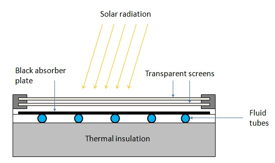
The flat-plate solar collectors are probably the most fundamental and most studied technology for solar-powered domestic hot water systems. The overall idea behind this technology is pretty simple. The Sun heats a dark flat surface, which collect as much energy as possible, and then the energy is transferred to water, air, or other fluid for further use.
These are the main components of a typical flat-plate solar collector:
- Black surface - absorbent of the incident solar energy
- Glazing cover - a transparent layer that transmits radiation to the absorber, but prevents radiative and convective heat loss from the surface
- Tubes containing heating fluid to transfer the heat from the collector
- Support structure to protect the components and hold them in place
- Insulation covering sides and bottom of the collector to reduce heat losses
The flat-plate systems normally operate and reach the maximum efficiency within the temperature range from 30 to 80 oC (Kalogirou, 2009), however, some new types of collectors that employ vacuum insulation can achieve higher temperatures (up to 100 oC). Due to the introduction of selective coatings, the stagnant fluid temperature in flat-plate collectors has been shown to reach 200 oC.
Probing question
- What are the typical materials used for absorber plates and glazing covers?
We partially discussed material choices and properties in Lesson 2. However, you are encouraged to look wider and review the current innovations in the flat-plate designs. For the discussion in this lesson, you will be asked to share what you found during your search and describe the state of the art materials that help increase collector performance.
Some advantages of the flat-plate collectors are that they are:
- Easy to manufacture
- Low cost
- Collect both beam and diffuse radiation
- Permanently fixed (no sophisticated positioning or tracking equipment is required)
- Little maintenance
Flat-plate collectors are installed facing the equator (i.e. South oriented in the Northern hemisphere and North oriented in the Southern hemisphere). The optimal tilt of the collector plate is close to the latitude of the location (+/- 15o). If the application is solar cooling, the optimum installation angle is Latitude - 10o, so that the solar beam is perpendicular to the collector during summertime. If the application is solar heating, the optimum installation angle is Latitude + 10o. It was found however, that for year-round hot water application, the optimum angle is Latitude + 5o, which provides somewhat better performance during winter, when the hot water is more needed (Kalogirou, 2009)
Transport fluid options
The flat plate collectors can involve liquid or air heat transport.
Water is one of the common options as liquid fluid due to its accessibility and good thermal properties:
- It has a relatively high volumetric heat capacity
- It is incompressible (or almost incompressible)
- It has a high mass density (which allows using small tubes and pipes for transport)
One disadvantage of water is that it freezes during winter, which can damage the collector or piping system. This can be managed by draining down the collector at low solar inputs (below a critical insolation threshold). Drain down sensors are often employed to monitor the system and to ensure complete draining, as pocket water freezing can cause damage. Refilling the system with water on the next morning also is not perfect. Possible air pockets in the collector can be a problem, blocking water flow and decreasing system efficiency (Vanek and Albright, 2008).
Antifreeze mixtures can be used instead of pure water to alleviate the above-said problems. The common antifreeze components are ethylene glycol or propylene glycol. Those chemicals are mixed with water require closed-loop systems and proper disposal due to toxicity. Nominal antifreeze service like is about 5 years, after which it needs to be replaced.
Air can be used as transport fluid in some designs of flat -plate collectors. This option is better suited to space heating applications or crop drying. A fan is usually required to facilitate air flow in the system and efficient heat transport. Certain designs can provide passive (no fan) movement of air due to thermal buoyancy.
Phase-change liquids can also be used with flat-plate collectors. Some refrigerants are included in this group of fluids. They do not freeze, which eliminates troubles explained above for water, and, due to their low boiling point can change from liquid to gas as temperature increases. Those fluids can be practical in settings where quick response to rapid temperature fluctuation is needed.
Collector construction
The key considerations in flat plate collector design are maximizing absorption, minimizing reflection and radiation losses, and effective heat transfer from the collector plate to the fluids. One of the important issues is obtaining a good thermal bond between the absorber plate and changes (tubes or ducts containing the heat-transfer fluids). Different construction designs (shown below) try to address this issue.
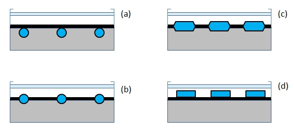
The plate - channel assembly may use a variety of methods of component attachment - thermal cement, solder, clips, clamps, brazing, mechanical pressure applicators. One of the considerations in choosing the assembly method is cost of labor and materials.
Next, we are going to look at the energy transfer and balance within the flat-plate collector.
References:
- Kalogirou, S.A., Solar Energy Engineering, Elsevier, 2009
- Vanek, F.M, and Albright, L.D., Energy Systems Engineering, McGraw Hill, 2008.
3.2 Energy Balance in Flat-Plate Collectors
A fundamental concept for thermal analysis of any thermal system is the conservation of energy, which can be analyzed through energy balance calculation under steady state conditions. In steady state, the useful energy output of the collector is the difference between the absorbed solar radiation and the total thermal losses from the collector
Useful energy = Absorbed solar energy - Thermal losses
Obviously, the higher the useful energy output from a particular design, the higher the expected efficiency. Thermal efficiency of the collector is an important parameter to consider in this kind of analysis as it creates the basis for comparison of different materials and modifications of collector systems. So many theoretical calculations presented in the books (as well as in this Lesson), are eventually aimed at evaluating efficiency.
Let us define the thermal efficiency (η) first, as it will be the focus and final destination of this chapter.
\[\eta = \frac{{{Q_u}}}{{{A_c}{G_T}}}\]
where Qu is the useful energy output from a collector, GT is the incident solar radiation flux (irradience), and Ac is the collector area. So the denominator here is the total energy input for the collector. In this formula the GT is the parameter characterizing the external conditions, and it is usually known from practical measurements (with a pyranometer) or assumptions for a specific location. The collector area is a set technical characteristic. So the main question here is how to estimate the Qu - the useful energy.
As was mentioned above, to find how much energy remains available for useful thermal work, we need to understand the energy balance within the collector: absorbed energy - losses.
The energy balance can also be expressed via the following key equation:
\[{Q_u} = {A_c}[S - {U_L}({T_{plate}} - {T_{ambient}})]\]
where S is the absorbed solar radiation, UL is the total losses, Tplate is the temperature of the absorbing plate, and Tambient is the temperature of the air, and Ac again is the area of the collector surface.
This equation stands as a cornerstone of the energy balance analysis presented in Chapter 6 of Duffie and Beckman's textbook. To implement this question, we need to understand how the quantities S and UL can be obtained. The most complete explanation can be found in the following reading.
Reading Assignment
Look through the following section of the D&B textbook to understand the ways to estimate the absorbed radiation S on a collector surface
Duffie, J.A., and Beckman, W.A., Solar Engineering of Thermal Processes, Wiley and Sons, 2013, Chapter 5, Section 5.9 (3 pages).
Equations (5.9.1) and (5.9.3) in the above reading provide the basis for estimating absorbed radiation depending on what initial information on incident radiation is available.
In a general case, when measurements of incident solar radiation (IT) are available, the convenient approximation for the absorbed energy is given by:
\[S = {(\tau \alpha )_{av}}{I_T}\]
where (τα)av is the product of transmittance of the collector cover and absorptance of the plate averaged over different types of radiation. In fact, (τα)av ≈ 0.96(τα)beam based on practical estimattions.
Now let us see how the radiation losses can be determined. Please refer to the following reading.
Reading Assignment
Duffie, J.A., and Beckman, W.A., Solar Engineering of Thermal Processes, Wiley and Sons, 2013, Chapter 6, Sections 6.1-6.4 (18 pages).
These sections of the book explain the model and assumptions for flat-plate collector analysis. The thermal losses are specifically addressed in Section 6.4, and you are welcome to dig through the complete derivation and examples. Of practical interest are the charts in Figure 6.4.4 which describe the results of the model calculations of thermal loss coefficient versus plate temperature.
Another useful outcome from this chapter is the empirical equation (6.4.9), which offers an algebraic method of finding the losses from the top of the collector. You will have a chance to look closer at this equation and see how it works further in this lesson activity.
Now as the absorbed radiation and losses are defined, the useful energy gain can be determined via the energy balance equation given above.
3.3 Flat Plate Collector Performance and Characterization
The maximum possible useful energy gain can be achieved when the collector is at the same temperature as the inlet fluid. In this case, the heat losses are minimized. However, in an actual operation setting, this is not always the case. To describe the effective (actual) useful energy gain via heat exchange, we should introduce the heat removal factor - FR
This coefficient shows how much energy remains after heat losses to the surrounding due to collector and inlet temperature difference. Therefore, the energy balance equation for the actual system can be written as follows
\[{Q_u} = {A_c}{F_R}[S - {U_L}({T_i} - {T_a})]\]
This equation reminds us the energy balance equation discussed in the previous page of this lesson, only with the FR factor. This flow factor depends on the mass flow rate of the fluid and heat capacity, and you can learn more details about the flow factor and practical application of the above equation from the following reading.
Reading Assignment
Duffie, J.A., and Beckman, W.A., Solar Engineering of Thermal Processes, Wiley and Sons, 2013, Chapter 6, Sections 6.7 (4 pages).
The theoretical models and calculations described in the D&B textbook can be checked in practice by performing collector tests. As new materials and new collector designs appear on market, there is a need for standardized testing procedure, and metrics, which would allow clear comparison and assessment if a collector performance is good or not so good.
The basic method of assessment of collector performance is to expose the system to solar radiation, run the fluid through it, and measure the inlet and outlet temperature along with the flow rate. Then the useful energy gain can be calculated from the experimental data as follows
\[{Q_u} = m{C_p}({T_o} - {T_i})\] In addition the incident radiation on the collector (GT) and ambient temperature (Ta) can be recorded, so we can express the useful gain in terms of incident radiation:
\[{Q_u} = {A_c}{F_R}[{G_T}{(\tau \alpha )_{average}} - {U_L}({T_o} - {T_i})]\]
and further the experimental efficiency of the system at each instant of operation can be obtained:
\[\eta {}_i = \frac{{{Q_u}}}{{{A_c}{G_T}}}\]
To see how the collector test data and efficiencly look like in practice, please refer to the following reading:
Reading Assignment
Duffie, J.A., and Beckman, W.A., Solar Engineering of Thermal Processes, Wiley and Sons, 2013, Chapter 6, Sections 6.15-6.18 and 6.23 (16 pages).
Make sure to complete all the assigned reading in this lesson and take the reading quiz.
3.4 Assignment
This homework assignment consists of two quantitative problems that are closely tied with the readings. Please study examples in Chapter 6 (D&B book) as they can be especially helpful in developing the solutions.
Deliverable - Lesson 3 Assignment
Problems: 6.1 and 6.12 from the D&B textbook (see Appendix A)
Again I ask you to complete these problems by hand, clearly showing your work step by step. While you should feel free to use any calculation software or spreadsheets behind scenes, I will only read and grade your hand-written solutions. The recommended format for hand-written problems should include underlined statements of:
- knowns
- assumptions
- properties to find
- analysis (including what equations used, numbers, and units)
- solution (please draw a box around your final answer)
A sample hand-written problem is given in the Lesson 2 Module in Canvas.
Please create electronic images of your hand-written solutions (via scan or camera) and save them in a single PDF document. If you have series of images of your pages, you can first insert them into a MS Word document in proper order, and then save the file as PDF.
The assignment is due by 11:59 p.m. (Eastern Time) on Wednesday. Please see the Calendar in Canvas for specific due dates.
3.5 Summary and Final Tasks
Summary
Flat plate collectors come in various shapes, sizes, materials, and configurations. This type of collectors represent a good model for understanding the energy balance and system performance.The basic principle of absorbing as much solar radiation as possible (via black absorptive surfaces) while minimizing losses to the surrounding environment as much as possible (via glazing surfaces, insulation, and vacuum tubes) can be accomplished by various technologies trading off the level of performance and material and manufacturing costs. Being able to discern between flat plate technologies for different applications and locales based on the underlying physics is a valuable skill to have.
Reminder - Complete all of the Lesson 3 tasks!
Please double-check the to-do list on the Lesson 3 Introduction page [2] to make sure you have completed all of the activities listed there before you begin Lesson 4.