
2.5 CPC Collectors - Concentration of Diffuse Radiation
The compound parabolic concentrators (CPC) are typical representatives of non-imaging concentrators, which are capable of collecting all available radiation - both beam and diffuse - and directing it to the receiver. These concentrators do not have such strict requirements for the incidence angle as the parabolic troughs have, which makes them attractive from the point of view of system simplicity and flexibility. Like parabolic and other shapes, CPC concentrators can be applied in both linear (troughs) and three-dimensional (parabolocylinder) versions. The same as in "pure" parabola case, troughs are most widespread and useful for this type of concentrator.
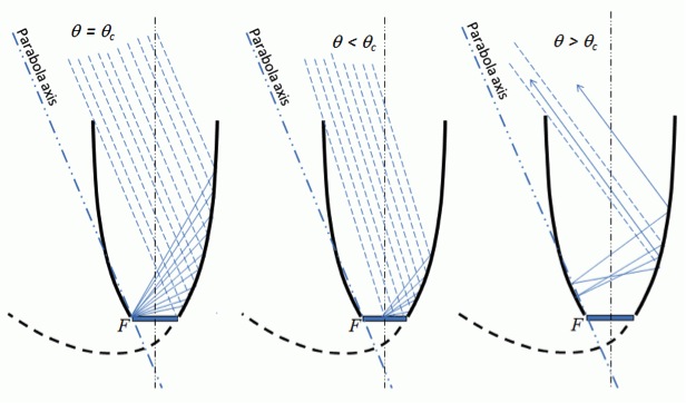
The geometry of a CPC collector is demonstrated in Figure 2.12. If we consider a CPC trough, this diagram represents its cross-section. Each side of the shape is a parabola, and each of the parabolas has its focus at the lower edge of the other parabola (e.g., F is the focus of the right-hand parabola in Figure 2.12). Each parabola axis is tilted relative to the axis of the CPC shape. One of its key parameters is acceptance half-angle (), which is the angle between the axis of the collector and the line connecting the focus of one of the parabolas with the opposite edge of the aperture. The collector is designed in such a way that each ray coming into the CPC aperture at an angle smaller that reaches the receiver; if this angle is greater than , the ray will return (Figure 2.13). The relationship between the size of the aperture (2a), the size of the receiver (2a') and the acceptance half-angle is expressed through the following equation:
| (2.11) |
Knowing that the geometric concentration ratio is the quotient of the aperture area to the receiver area (see Section 2.3), for a linear CPC concentrator, we can obtain the relationship between the concentration ratio and the acceptance angle:
| (2.12) |
One large parabolic mirror with a second mirror sitting tangent to the parabolic axis with an end at mirror #1’s focus. The distance between the two upper ends of the parabolas is labeled aperture (2a) and the bottom two ends is labeled receiver. Dashed lines connect one top end to the opposite bottom end. The angle between their y intercept, y-axis and upper tip represents the acceptance half-angle.
There are some other useful expressions that describe the design of CPC concentrators. The following equations relate the focal distance of the side parabola (f) to the acceptance angle, receiver size, and height of the collector (Duffie and Beckman, 2013):
| (2.13) |
| (2.14) |
Please complete the following reading to further explore the work principle of CPC concentrators.
Reading Assignment
Book chapter: Duffie, J.A. Beckman, W., Solar Engineering of Thermal Processes, Chapter 7: Sections 7.6 and 7.7 - pp. 337-349. This book is available online through the PSU Library system and can also be accessed through e-reserves (via the Library Resources tab).
Section 7.6. of this book covers the fundamental optical principles of CPC collectors and also considers particular cases of truncated collector. Some practical examples are also presented. Section 7.7. talks about the orientation of CPC collectors. While CPC technology does not require continuous tracking, proper orientation with respect to the sun position is crucial to maximize absorbed radiation. The theoretical material in this section is also supported by practical examples.
The following self-check questions will help you to test check your learning of the principles of CPC collectors: