
4.3. How PV performance is measured
In the previous section, we understood how the photo-induced electric current is be generated at the p-n junction due to photovoltaic effect. How can we estimate the magnitude of that electric current?
To answer this question, first let us define the electron traffic across the band gap as generation or light-induced current (IL). Therefore, each photon absorbed is responsible for contributing one electron to the generation current inside the device. Hence, we can write:
where IL is light-induced generation current, q is the electron charge, N is the number of photons absorbed, and A is the surface area of the semiconductor exposed to light. Logically, we see that the more photons are absorbed, the higher the generation current. Also, the greater the area of semiconductor exposed to light, the higher the generation current. To be independent of the size of the cell, we can express this relationship in terms of current density (JL), which is current normalized by area:
For example, we can try to use this equation to estimate the current density of a photovoltaic device corresponding to the typical terrestrial light spectrum. Inputting values for electron charge (1.6 x 10⁻¹⁹ C) and number of photons in the absorbed range of spectrum for crystalline silicon (4.4 × 10¹⁷) to the above equation, we obtain:
(4.3)
This is the maximum current density that could be expected from a silicon cell, if there were no losses, and if all of the electrons were perfectly transferred through the external circuit. In reality, current losses take place, so the actual measured current density will be less than that ideal value (Markvart, 2000).
Next, let us see how the solar cell voltage can be estimated. The maximum voltage of a solar cell is determined by the semiconductor band gap. The electrostatic energy available due to separation of electrons and holes cannot exceed the band gap energy; otherwise, recombination would occur. The cell voltage (V) upper limit is therefore set by the following expression:
Numerically, the maximum voltage in volts is equal to the band gap energy in electron-volts. For example, the maximum voltage for a silicon solar cell is Vmax = 1.1 V
The same as with maximum current, the maximum voltage is never achieved practically because of losses and process limitations. However, in general, based on Eq. (4.4), the semiconductors with greater band gap indeed produce higher voltage (Markvart, 2000).
In summary: the maximum electric current of a solar cell is determined by the generation current, and the maximum voltage of a solar is determined by the material band gap.
In the above description, for simplicity, we assumed that all the photons (with energy above the band gap) reaching the surface are absorbed and transfer their energy onto electrons. This would be ideal and would give us ideal generation current. As a matter of fact, absorption of photos by semiconductors is material dependent and is controlled by the absorption coefficient. This is an important property to take into account, since it directly affects the charge carrier generation rate.
Reading Assignment
Absorption Coefficient / PVEducation.org
Generation Rate / PVEducation.org
The absorption coefficient role is well explained by these articles. Read through it to understand how the absorption coefficient affects the generation rate and how it changes with depth of the semiconductor material.
At this point, we have already recognized that the key parameters describing the performance of a solar cell are current density and cell voltage. We have looked into their origin - how they develop in the cell due to the photovoltaic effect, and looked at some factors that affect that process. Now, we will proceed to examination of the I-V characteristic (a.k.a. performance curve) and see how it is obtained and what different parts of this curve tell us about.
Using electric circuit notation, a solar cell can be represented by a diode, which represents the p-n junction.
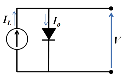
The current through the diode (Io) is the exchange current present when the element is in the dark. This is a small current compared to light-induced current (IL), which passes through the external load. The net current is the difference between the light and dark currents, or including Shockley diode equation:
where V is cell voltage, q is the charge of electron, k is the Boltzmann constant, and T is absolute temperature. This is the main equation that describes the relationship between voltage and current in the solar cell in operation. If we plot the cell voltage versus current (or current density), we will obtain the curve that generally looks like this (Figure 4.5):
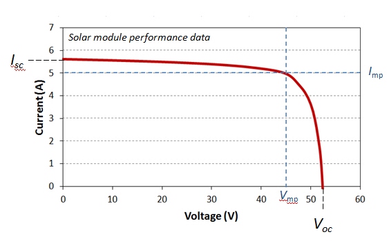
There are several important conditions to note on this curve. We see that at current being zero, the cell has the highest voltage. Because there is no current, the cell does not produce any work, but the voltage magnitude indicates the potential of the cell to do work. This is the open circuit voltage (Voc or OCV). The OCV is a very important characteristic of any galvanic cell (including solar cells), and it depends on the cell material. By re-arranging equation (4.5), and setting the net current to zero, we can express the open circuit voltage as follows:
At cell voltage set to zero, the cell current reaches some maximum limiting value, which is called short-circuit current (Isc). This is the kinetic parameter that shows the maximum current the cell is able to generate. It depends on the number of photons being absorbed by the material, optical properties of the cell and its size. You can imagine that if the sunlight intensity decreases for any reason, we will see a decrease in the short circuit current for a particular device. In an ideal case, the short-circuit current is equal to light-induced current: Isc = IL.
At any point on this curve (in Figure 4.5), we can define power output as follows:
At some point, the power will reach its maximum point, and the current and voltage corresponding to that point are defined as maximum power voltage (Vmp) and current (Imp):
These parameters are shown in the diagram in Figure 4.5. by blue dashed lines. They characterize the conditions when the cell produces the highest power output. This point is important because it is where the cell efficiency is usually determined.
At the maximum power point, we can also define the characteristic resistance of the cell (Rch). If the resistance of the external load is equal to Rch, then the maximum power is transferred to the load. The characteristic resistance can be determined from the Ohm's law:
The next term we need to define, when talking about the cell power output is the fill factor (FF). Please refer to the following reading to learn about the fill factor.
Reading Assignment
You are also welcome to try the FF calculators provided, which utilize the equations described on that website.
As you should have noted from the reading, the fill factor can be calculated as follows from the cell performance parameters:
The fill factor is a convenient metric to characterize the solar cell performance. For cells that work well, FF>0.7. Typical parameters of the single-crystal silicon solar cell are (Kalogirou, 2009):
Jsc = 32 mA/cm2
Voc = 0.58 V
Vmp= 0.47 V
FF = 0.72
Pmax = 2273 mW
Based on equation (4.10), the maximum power output of the PV system can be readily found using equation (4.11) if we know open-circuit voltage, short-circuit current, and fill factor.
The I-V characteristic is a convenient tool to explore the effect of various external variables on the cell performance. What is going to happen to a module output if temperature rises? What if light intensity drops because of the clouds? If cell is damaged or has bad contact with current collectors, how will it be reflected on the performance curve? Learn about these effects from the following readings:
Reading Assignment
Each of the following links will take you to a PVEducation web page that describes a certain effect on the solar cell performance. Read and take a note what events during the cell operation can cause these negative (parasitic) or positive effects (PVEducation.org).
Check Your Understanding - Question 4 (Essay)
Find the characteristic resistance of a solar cell that displays voltage of 40 V and current of 4 A at the maximum power point.
Rch =
Check Your Understanding - Question 5 (Essay)
Find the maximum power output of a PV system, if the open circuit voltage is 0.6 V, the short-circuit current is 0.32 A, and the fill factor is 0.8.
Pmax=