Lesson 9: Energy Storage Technologies for Solar Systems
Overview
Overview
This lesson will overview energy storage options for large-scale solar facilities. Clearly, energy demand rarely coincides with energy generation. Being bound to daily solar activity cycle at a certain locale, solar energy conversion systems are intermittent by nature, therefore, using energy at nighttime requires technologies to store energy on site. Photovoltaic systems, which convert natural solar resource into electric power, require means for electrical energy storage, while CSP systems may be better off storing thermal energy. The thermal storage principles and technology were discussed in the previous lesson, and Lesson 9 is primarily concerned with the technologies used to store electric power. For storage, electrical energy is often converted to other kinds of energy; for instance, potential mechanical, kinetic mechanical or chemical energy, which would be stored as fuel. Energy storage research has been accelerated over the recent years to address the need for compact and economically efficient storage technologies and is currently define the rate implementation of the commercial renewable energy systems. This lesson readings provide an overview and resources for learning the storage technology principles, with understanding that some of those options are much more advanced and rapidly evolving than others.
Learning Outcomes
By the end of this lesson, you should be able to:
- explain the technical principles of energy storage used in utility-scale solar plants;
- understand the performance metrics for storage systems;
- articulate technological, environmental, and economic cons and pros of energy storage implementation.
Readings
Book Chapter: Foster, A., Chassemi, M., and Cota, A., Solar Energy: Renewable Energy and the Environment. CRC Press, 2010. Chapter 11. Energy Storage, pp. 265-293.
Book chapter: Butler, P.S., Eidler, P.A., Grimes, P.G., Klassen, S.E., and Miles, R.C., Zinc/Bromine Batteries [1], in Advanced Battery Systems, pp. 37.1-37.15. Sandia National Laboratories, 2000.
Web article: Vanadium Redox Flow Batteries [2], Energy Storage Association (ESA), 2015.
DOE Fact Sheet: Wang, E., Vanadium Redox Flow Batteries [3], U.S. Department of Energy, Energy Storage Program, 2012.
Review paper: Blanc, C. and Rufer, A., Understanding the Vanadium Redox Flow Batteries [4], in Paths to Sustainable Energy, Dr Artie Ng (Ed.), ISBN: 978-953-307-401-6.
Web article: LaMonica, M., Compressed Air Energy Storage Makes a Comeback [5], IEEE Spectrum, 2013.
Book Chapter: Grimes, C., Varqhese, O.K., Ranjan, S., Light Water Hydrogen. The Solar Generation of Hydrogen by Water Photoelectrolysis, Section 2.2 Hydrogen Generation by Water Splitting. pp. 35-52.
9.1. Options for energy storage
9.1. Options for energy storage
Because solar energy supply is variable in time, energy storage is an important issue. Energy storage is used to collect the energy generated by the solar conversion systems (thermal or photovoltaic) in order to release it later on demand. This can be a situation when sufficient power is produced during the day, and stored energy is used during the night. Also, when insolation conditions are ideal, the solar system may produce enough power for the target application, but on dull days, direct energy supply from collectors is diminished, and the energy from the storage is used to compensate the deficit. Energy storage devices help to smooth out differences and minor fluctuations in energy supply caused by shading, passing clouds, etc. Development of efficient and cost-effective energy storage is considered the main bottleneck of the universal development of solar systems.
Video: How solar energy got so cheap, and why it's not everywhere (yet) (7:53)
Introduction
Narrator: Solar. It's astonishing. But clean energy from the sun. Solar energy has become the cheapest way to generate electricity. It's even cheaper than coal. And yet it produces only 3% of the world's electricity. Why aren't we using way, way more of it? How did it get so cheap? And what does all this have to do with ducks? Let's find out.
How solar energy got so cheap
Narrator: First, Let's take a look at how much the price for solar has fallen.
Jenny Chase, Head of Solar, BloombergNEF: I started this job as an analyst of solar in 2005, and then I thought, solar is ridiculously expensive.
Narrator: Jenny Chase is the head solar analyst at research firm Bloomberg NEF.
Jenny Chase: You'd pay about pay about $4 a watt for a solar panel, and today you'd pay about $0.20 for that same watt.
Narrator: And that is just the last 15 years. If you look further back, the price drop is even more impressive. How did this happen?
Gregory Nemet, Author, “How Solar Became Cheap”: It's been a long story, but it's unbelievable.
Narrator: Gregory Nemet has written a book about this.
Gregory Nemet: No one country did it. It was an exchange of one country building on another. One, the US created the technology.
Narrator: The modern day solar cell, made from silicon, was invented in the US in 1954. Back then, it mainly got used in the space industry and was still super expensive. But as the technology progressed, prices started to fall.
Gregory Nemet: Two, Germany created a market.
Narrator: In 2000, Germany passed a law to boost renewable energy development. This was big because it put a fixed price on energy generated from sources like wind or solar. That gave people and companies a reason to set up solar panels. And for them to do that, someone needed to build these solar panels.
Gregory Nemet: Three, China made it cheap.
Narrator: Once the German Lohat came into force, China really started to pump out those solar cells.
Jenny Chase: So basically, it built a whole industry for this on a scale that the west really didn't keep up with.
Gregory Nemet: China was almost a nonexistent player 20 years ago, and today they're the biggest producer of solar panels, about 70% of the world's production.
Narrator: So this is how we ended up where we are now, with clean energy. That also makes business sense. But if solar is so great, why don't we rely on it much, much more and just switch off all these dirty power plants? Well, solar has always had this one big problem. It only really works when the sun is shining, when it's cloudy, or even worse, dark. Even the best solar cells are pretty useless. And that's a real shame, because that's when we'd need them the most. Let's take a look at how we use energy. In the morning, when most people get up and get ready. We need energy. The so-called duck curve charts our demand for power from nonrenewable sources like coal and gas, throughout the day, first, in places without much solar. After the morning spike, it stays pretty level. When people come home in the evening, it goes up again and then drops at night. At this point, you might get an idea why they call it the duck curve, because it kind of looks like a duck. Anyway, in places with lots of solar, like California, this curve changes. The mornings are pretty much the same.
Then the sun rises and solar energy production kicks in. This lets demand for non renewable energy drop until the sun sets, that is. That is when conventional demand shoots up again, way steeper than in the first curve. Two problems with this. One, traditional power plants suck at ramping up this quickly. That means you have to keep them running at a certain output all day, even though there's lots of solar. And that means….
Jenny Chase: That you can end up with actually more power produced in the middle of the day than is used.
Narrator: And that leads to the second problem. There are limits to how much energy you can put into the grid. Too much solar could overpower it, so it needs to be thrown away. This has always made it super difficult to add lots of solar to power systems. But guess what? There is now a solution to this, and chances are you have part of it in front of you right now. A lithiumion battery.
Lithiumion batteries
Gregory Nemet: We're just taking that same construction, stringing together many, many of those cells, and making battery packs that we can use for cars. And then we can also scale that up to use for stationary power to go next to wind parks or solar farms.
Jenny Chase: What's been quite good over the last few years is that batteries have got a lot cheaper as well. And we're now seeing solar projects built with a couple of hours of storage in the battery, so that they could shift solar generation from the middle of the day to the evening, where there's often a peak in electricity demand.
Narrator: In the US, for example, the state of New Mexico just decided to shut down a coal plant and instead build new solar farms that store large amounts of the energy they produce in batteries. Lithiumion batteries have become a lot better and a lot cheaper than expected in the last few years. They're now a viable option for storing and shifting at least a few hours worth of solar energy as needed. So the storage problem that solar always had is actually not that much of a problem anymore. Sometimes, though, we might want longer term storage in places without much sunshine, for example. And that's why companies are offering other solutions. Let's just run through a few.
Alternatives
Narrator: Another type of battery, called a flow battery, separates the charge outside a cell. That has two advantages. It can store more energy and for longer. The problem is they're still relatively expensive. Then there's pumped hydro storage, which is already used quite a bit. You need two lakes, and one of them needs to be in a hill. During the day, you use solar energy to pump water from the lower lake up to the higher lake. When you need energy at night, you can just let it run down through a turbine.
But for that you need to find lakes and, well, a hill. Another solution using gravity comes from a swiss company. It's working on a tower that raises building blocks with solar energy and then releases the energy by lowering them again. But for this too, you need space. And there's also the option of using solar to produce hydrogen. And with that hydrogen, you could then do a number of things like fuel cars, or even make steel. But the whole process is still pretty costly.
Jenny Chase: I think that the storage will mostly be lithiumion. With some hydrogen and maybe a few other options.
Gregory Nemet: There are alternatives. It's just that lithiumion batteries are becoming so flexible and so inexpensive that it'll be hard for these alternatives to compete them. But they do have other attributes, like they hold a charge longer, which could turn out to be play a pretty important role in some applications.
Narrator: Solar has become cheap and has pretty much fixed its biggest problem. So what's next?
Jenny Chase: It's going to be big. It's going to be everywhere. We forecast that even with no further policy, solar would supply about 23% of global electricity by 2050. I personally think it's going to be much higher than that.
Gregory Nemet: I would not be surprised if by 2030, we're talking about solar doing a large part of the world's electricity supply.
Narrator: Solar has come a long, long way. But now that the technology is in place, it really looks like it's time to shine. Now we'd like to hear from you. What are your thoughts on solar energy? Let us know in the comments. And hit subscribe for more videos like this every Friday.
There are quite a few different technology options for energy storage, which are briefly outlined below:
- Grid. For grid connected solar systems, the most natural and cost-effective way would be to store energy in the grid. The main idea here is that the DC power from a solar facility (array or farm) is converted to AC power and is fed to the grid and further on is used for on-site or off-site applications. This way, the grid acts as the medium that collects energy from different power-making facilities (renewable or non-renewable) and redistributes it as necessary. Since a grid does not really represent a separate system that is part of a solar plant, it will not be discussed further in this lesson.
- Fluid. Fluid-based storage is typically used with solar thermal systems. Unlike grid, which stores electrical energy, fluids store thermal energy. Fluids, such as water, oil, molten salt or others act as a medium for absorbing heat. The main idea is that the solar radiation heats the heat-transfer fluid which is accumulated in the tank. The tank is insulated, so the hot fluid keeps its temperature for a substantial period of time. When needed, the heated fluid is used in a heat-exchanger to produce steam for the electric generator. This type of thermal energy storage was discussed in more detail in Lesson 8.
- Battery. A battery is an electrochemical device that stores chemical energy in internal components and releases energy as electricity, which is generated through electrochemical reactions. Batteries are reversible, i.e., can be charged and discharged, and the parameters of these processes are regulated to avoid damage by overcharging or over-discharging. Battery life is expressed in number of charge-discharge cycles. There are many different types of batteries, some of which will be discussed further in this lesson.
- Hydrogen. The idea behind hydrogen storage is that electricity generated by solar PV systems can be used to electrolyze water - to split it to hydrogen and oxygen. Further, hydrogen gas is collected and can be used as a fuel. One of the highly efficient devices "converting" hydrogen back to electricity is H2/O2 fuel cell, which has zero carbon footprint during operation.
- Compressed air. In this case, the electrical energy produced by a PV solar system is used to run compressors to compress massive amounts of air and store it in underground, above-ground, or underwater containers. Later on, when energy is needed, the air is decompressed and is supplied to a turbine to generate electricity. Compressed air energy systems (CAES) promise high efficiencies, although this technology is not yet widely implemented.
- Pumped storage hydropower. The available energy can be used to pump water into an elevated reservoir for storage. When power is needed, the water can be discharged under gravity to run a turbine, which is connected to a generator to produce electricity. The same as compressed air systems, the pumped storage technology has high energy return on investment, although it may require special topographical conditions and water availability in order to be used.
All of the above options for energy storage should be employed with understanding the facility needs and capacity. What energy storage is efficient for small residential systems may be insufficient or too costly when scaled up to the utility-size systems. Determining capacity of energy storage for a particular solar project is an important technical and economic issue. For example, if the capacity of the storage is too large compared to the energy produced by the solar conversion facility, the total system cost will be unnecessarily increased. On the contrary, if the capacity of the storage is too small, that leads to energy dumping and overall unsatisfactory plant performance.
In the following sections, we will discuss different energy storage options that can be possibly applied to utility scale solar systems.
9.2. Battery storage
9.2. Battery storage
Batteries are commonly used to store electric energy generated by off-grid renewable energy systems, and also to mitigate the sharp fluctuations of power for on-grid systems. While there are many different types of battery technologies, some are more applicable to utility scale energy storage than others. Applicability to large systems depends on such factors as cost of materials, ability to scale up with no ill effects or performance loss, and design and operation mode.
Some well-known examples of battery types used as stationary storage system for PV solar are listed in Table 9.1
| Technology (battery type) | Power subsystem cost $/kW | Energy storage subsystem cost $/kW | Charge-discharge efficiency % | Cycles |
|---|---|---|---|---|
| Advanced lead-acid | 400 | 330 | 80 | 2,000 |
| Sodium/sulfur | 350 | 350 | 75 | 3,000 |
| Lead-acid with carbon enhanced electrodes | 400 | 330 | 75 | 20,000 |
| Zinc/bromine | 400 | 400 | 70 | 3,000 |
| Vanadium redox | 400 | 600 | 65 | 5,000 |
| Li-ion (large) | 400 | 600 | 85 | 4,000 |
| Flywheels (high-speed composite) | 600 | 1,600 | 95 | 25,000 |
| Super capacitors | 500 | 10,000 | 95 | 25,000 |
Note: The costs in the table are based on standard assumptions for the applications and technologies considered, and on expert opinion. They are meant to be used for comparative purposes. The actual costs of any storage system depend on many factors and the assumptions and the means of calculating some of the values are subjective and continue to be debated, even among experts in the field (Sandia National Laboratories).
For quite a while, lead-acid batteries have been the first choice for off-grid PV applications. This lead-acid battery technology has been around since the 19th century and, historically, service providers have more knowledge and tools to deal with those systems. But, despite their long existence and widespread use, lead-acid batteries remain one of the lowest energy-to-weight and energy-to-volume battery designs, which means they are too big and heavy for the amount of energy they provide. This technology is inexpensive and reliable, and it may be a while before it is replaced by more advanced types on a wide scale.
The following reading provides more information on the battery storage types and lead-based batteries, specifically.
Reading Assignment:
Book Chapter: Foster, A., Chassemi, M., and Cota, A., Solar Energy. Renewable Energy and the Environment. CRC Press, 2010. Chapter 11. Energy Storage, pp. 265-293. (See E-Reserves via the Library Resources tab.)
Li-ion battery technology
Li-ion battery is one of the rapidly advancing technologies preferred for employment in conjunction with solar systems due to high storage capacity, high charging rates, light weight, and relatively long service life. However, the technology cost is still high and can be a limitation on the utility scale. Some of the very attractive features of Li-ion batteries are high power output and high charge-discharge efficiency. They can also withstand more charge-discharge cycles than lead-acid batteries.
The principle of operation of the Li-ion battery is discussed below.
A schematic representation of a generic Li-ion battery is given in Figure 9.1. Roughly, Li-ion cell consists of three layers: electrode 1 (cathode) plate (usually lithium cobalt oxide), electrode 2 (anode) plate (usually carbon), and a separator. The electrodes inside the battery are submerged in an electrolyte, which provides for Li+ ion transfer between the anode and cathode. The electrolyte is typically a lithium salt in an organic solvent.
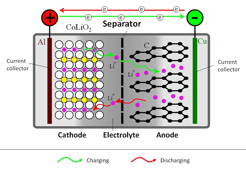
During the charging process, a DC current is used to withdraw Li+ ions from the cathode and to partially oxidize the cathode compound:
LiCoO2 → Li1-xCoO2 + xLi+ + xe–
The released Li+ ions migrate through electrolyte towards the anode, where they become absorbed in the porous carbon structure:
xLi+ + xe– + C6 → LixC6
At the same time, electrons travel through the external circuit (electrolyte is not electron conductive).
During the battery discharge, the reverse process takes place. Li+ ions spontaneously return to the cathode, where electrochemical reduction occurs.
Limitations of the Li-ion batteries are rooted in the material properties.
For example, the LiCoO2 ⇔ Li1-xCoO2 conversion is only reversible with x<0.5, which limits the depth of the charge-discharge cycle. But with a wider variety of materials available, research is underway to develop new generations of Li-ion batteries.
For example, take a look at the Sigma Aldrich [7] website, which lists multiple alternatives for cathode, anode, electrolyte, and solvents.
| Advantages | Limitations |
|---|---|
| 1. Relatively high energy density and potential of finding even better formulations. | 1. Circuit protection needed to avoid damaging high voltage / current. |
| 2. No need for priming - new battery is ready to operate. | 2. Aging - battery gradually loses its capacity even if not in use. |
| 3. Low self-discharge (compared to other types of batteries). | 3. Toxic chemicals are subject to regulations. |
| 4. Low maintenance. | 4. High cost of materials and manufacturing process. |
| 5. Capability to generate high current / power. | 5. Technology is not fully mature; varying components and chemicals. |
Supplemental reading on the status of Li-ion battery technology:
Goodenough, J.B. and Park, K.S., The Li-Ion Rechargeable Battery: A Perspective, J. Am. Chem. Soc., 2013, 135 (4), pp 1167–1176.
Etacheri, V., Marom, R., Elazari, R., Salitra, G., and Aurbach, D., Challenges in the development of advanced Li-ion batteries: a review, Energy & Environmental Science, 2011 (9), 3243-3262.
Flow Batteries
Flow batteries, unlike solid-state batteries, have their chemical components dissolved in liquid solutions, which can be pumped through the electrodes in a flow. If you are familiar with the concept of fuel cell, it is something similar in principle of operation, although it is still a closed loop system. A flow battery cell itself can be small, while the solutions can be contained in external storages. One of the advantages of the flow batteries is almost instant replacement of the electrolyte liquid, thus eliminating any gradient or concentration fluctuations at the electrodes. The main difference between the conventional batteries and flow batteries is that the energy is typically stored in the liquid phase in flow batteries. So, increasing the size of the storage tanks for the liquids allows easy scale-up of the battery to match a specific application.
Zinc-bromine flow battery storage
Zinc-bromine battery is a type of hybrid flow battery. It uses zinc bromine as the working solution, which is stored in two compartments, separated by a porous membrane. One compartment has a negative zinc electrode and the other compartment has a positive bromide electrode. During charge, supplied electricity (e.g., from a solar conversion system) is used to electroplate metallic zinc (Zn) on the negative electrode, while bromine (Br2) is generated on the positive electrode. During discharge, the opposite process occurs: Zn is dissolved to form Zn2+ ions in solutions, and bromine is converted back to bromide ions (Br-).
Here are the electrochemical reactions involved in this process:
Zn2+ + 2e- → Zn(s) - Reduction of zinc during battery charging
2Br- → Br2(aq) + 2e- - Oxidation of bromine during battery charging
The overall reaction is therefore:
Zn2+ + 2Br-⇔ Zn(s) + Br2(aq)
This reaction proceeds to the right on charging and to the left on discharging. The standard electrode potential for the overall reaction is 1.85 V, which is the maximum theoretical voltage that can be expected from a single cell. The battery cells are stacked to increase the overall storage capacity of the system.
The battery compartments are made of inert plastic. Unlike common batteries, which store electrolyte within the reaction chamber, zinc-bromine batteries have solution storage in the external tanks, from where it is circulated through the electrodes (flow battery type). The external bromide solution storage also helps maintaining required concentration of bromide throughout the reaction cycle.
This technology has been commercialized by ZBB EnerStore company, which engineered zinc-bromine batteries into 50 kWh modules, scalable up to bigger storage systems. Each module is a stand-alone system that includes all necessary software and hardware. Some advantages of this technology include high-energy density (75-85 Wh/kg), stability, i.e., good resistance to performance degradation, ability to operate at full output within a wide temperature range. Unlike most batteries, ZBB EnerStore batteries use non-reacting electrodes (i.e., electrodes are not reactants, but simply are substrates for reactions to take place), which helps minimize loss of performance from repeated cycling.
Watch this video (5:19 minute) for a demo of ZBB EnerStore solution for zinc bromide battery technology:
Video: ZBB EnerStore (5:19)
PRESENTER: Introducing ZBB EnerStore, ZBB Energy's third generation flow battery. ZBB has completely re-engineered its zinc bromide flow battery to be the most advanced and cost effective energy storage device for distributed energy projects, whether on or off the grid. The new design is easy to maintain and operates indoors or outdoors in the widest ambient temperature range of any flow battery, so there are no additional costs associated with constructing and maintaining a climate-controlled building. ZBB EnerStore batteries are self-contained, modular units and are easy to transport, so we can deliver an expandable solution that is virtually plug and play at your site with no on-site wiring needed. Although there are many different energy storage options to consider when compared to lead acid batteries, ZBB's flow batteries have a higher energy density, the lowest cost of ownership over a 20-year lifespan and are the most effective way to maximize the use of renewables. By utilizing energy storage with renewable power sources, diesel gensets can be configured to operate in backup mode only, reducing run time and fuel consumption, and you don't need to worry about the complexities of federal emission compliance. ZBB flow batteries are also "black start" capable. Most other energy storage systems need the grid to work. The ZBB EnerStore flow battery is well-suited for a variety of commercial applications with or without renewable energy sources and is readily configurable and scalable.
The ZBB EnerStore battery is built in 50 kilowatt hour modules and expandable to 500kWh in a singular enclosure. With multiple enclosures linking together, it can contain up to 2 megawatt hours or more on a single point of connection. Each battery module is comprised of eight cell stacks with 60 cells each, DC to DC converters, a self-regulating heat exchanger, electrolyte storage tanks, and built-in secondary spill containment. With ZBB's innovative, integrated DC bus architecture and converters on each module, there are no voltage limitations or concerns about system design and operation. In addition, ZBB's flow batteries operate without any special ventilation requirements. Since flow batteries are made with inert materials, they are safe to install. Electrolytes are never handled or replaced, only the cell stacks are changed out over the course of its life cycle. ZBB's flow batteries are environmentally friendly, made with highly-recyclable materials and recoverable at the end of their service life. Now let's take a look at how the zinc bromide battery works. ZBB's flow battery technology is based on the reaction between two readily available chemicals, zinc and bromine. The battery consists of a zinc anode and a bromide cathode, separated by a microporous separator. The aqueous solution of zinc bromide is circulated through the two compartments of the cell from two separate reservoirs.
During charge, electricity causes a reaction with the zinc bromide solution to electroplate zinc and form bromine on the battery electrodes. The reaction is reversed during discharge. The zinc and bromine reacts electrochemically to produce electricity while reforming the zinc bromide solution. Circulation pumps are used to allow the zinc and bromide to flow continuously throughout the cell stacks. While the electrolyte is flowing, an onboard computer calculates the state of charge of the battery module and directs when energy should be stored or if the stored energy should be discharged. An inline heat exchanger regulates the temperature of the battery module and keeps it within the standard operating range regardless of ambient temperature or rate of charge and discharge operation. The ZBB EnerStore can be left indefinitely at any state of charge, from 100% to completely discharged. The ZBB EnerStore battery is your answer for capturing multiple value streams, from time shifting, to firming of renewables or load management, to system backup. It's the best choice over a 20-year cost of ownership. Using EnerStore as part of ZBB's integrated management platform provides a continuous supply of energy and optimizes all of your interconnected resources, no matter your energy source or connection to the grid. ZBB, optimizing energy availability.
Reading Assignment
Learn more on Zn-Br battery technology:
Book chapter: Butler, P.S., Eidler, P.A., Grimes, P.G., Klassen, S.E., and Miles, R.C., Zinc/Bromine Batteries [9], in Advanced Battery Systems, Sandia National Laboratories, pp 31.1-37.15. (See E-Reserves via the Library Resources tab).
Vanadium Redox Flow Batteries
This type of battery utilizes the multiple redox states of vanadium (V) in its charge-discharge cycles. Vanadium is present in the dissolved form in the sulfuric acid medium, and because it is all-vanadium system, this type of battery is not susceptible to performance loss due to cross contamination.
During charging, the following half-reactions occur in two separate compartments of the battery:
V3+ + e– → V2+
VO2+ + H2O → VO2+ +2H+ + e–
Electrons are supplied from the solar energy conversion system as DC current onto non-reacting electrode dipped in the V3+ solution. As a result, V3+ is reduced to V2+. At the same time in the other compartment, vanadium (IV) species VO2+ is oxidized to vanadium (V) species VO2+, releasing the electron. On discharging, these reactions are reversed.
The summary process is expressed through the following reaction:
VO2+ + V3+ + H2O ⇔ V2+ + VO2+ + 2H+
The total voltage generated by a single vanadium redox flow battery is around 1.25 V in ideal case.
The main benefits of the vanadium redox flow batteries ability to go through "unlimited" number of cycles; they have a long lifespan (>20 years), quick charging, and high efficiency of the charge-discharge cycle (~80%). They are also more environmentally friendly in terms of component toxicity than many other types of batteries.
Reading Assignment
The following sources will help you to better understand the technical details of the vanadium redox batteries, as well as its challenges.
DOE Fact Sheet: Wang, E., Vanadium Redox Flow Batteries [3], U.S. Department of Energy, Energy Storage Program, 2012.
The vanadium redox flow battery technology is potentially suitable for extra-large utility scale applications. For example, the 200 MW VRB battery facility in Dalian, China, is expected to significantly increase the stability of the electric grid by supplying power during peak hours and emergency black-starts. Development of such a mega facility was enabled by its co-location with the VFB cell manufacturing factory, which is tapping into local vanadium resources. The Dalian battery is expected to become operational in 2020. Nearby wind power facilities have been forced to curtail electricity production – this battery facility hopes to reduce curtailing significantly.
Check out the story here [10].
Probing question
Will the Dalian energy storage facility become truly the largest battery in the world when brought online? What is the capacity of the largest Li-ion Battery storage built to date, and how does that compare?
Additional resources:
Review paper: Blanc, C. and Rufer, A., Understanding the Vanadium Redox Flow Batteries, in Paths to Sustainable Energy, Dr. Artie Ng (Ed.), ISBN: 978-953-307-401-6. pp. 333-337(Access the article in Canvas).
This paper is quite technical as it describes different models used to analyze the performance of the vanadium redox flow batteries. Read sections 1 and 2, which describe the electrochemical principles behind the battery operation. Reading further sections may be useful if you have a special interest in this topic, but is not required.
9.3. Compressed Air and Pumped Hydro
9.3. Compressed Air and Pumped Hydro
Compressed Air Storage
Compressed air storage technology may become an efficient solution of storing energy generated by large solar plants. The concept is as follows.
Air is used as the energy transfer medium. During the daytime, solar power is used to heat and compress air in an airtight chamber. When energy is needed, that compressed air can be expanded through a turbine or another expansion device to drive a generator to create electricity. Compressed Air Energy Systems (CAES) have been in use in some conventional power plants, and they are making a come-back as energy storage systems for renewable energy plants.
Traditionally, CAES technology used underground geological formations, such as salt caverns, as reservoirs for compressed air. While this approach was effective at some locations, it was not universal, as geology in some areas may be just unsuitable. A newer approach with CAES is to use human-made chambers - large pipes, such as those used for natural gas pipelines. While it involves more construction and installation, this type of artificial storage can be employed virtually anywhere and scaled up to the required capacity by simply using longer pipes.
Reading Assignment
Please read the following review to understand the basic principles and cons and pros of CAES:
Review article: Wang, J., Lu, K., Ma, L., Wang, J., Dooner, M., Miao, S., Li, J., and Wang, D., Overview of Compressed Air Energy Storage and Technology Development [11], Energies, 2017, 10, 991.
Please read the following article to learn about the new approach in CAES technology:
Web article: LaMonica, M., Compressed Air Energy Storage Makes a Comeback [5], IEEE Spectrum, 2013.
This article explores the idea of underwater compressed air storage, which may become an efficient storage solution for solar plants located near the coastline.
Web article: Dorminey, B., Underwater Compressed Air Energy Storage: Fantasy or Reality? [12] Renewable Energy World, 2014.
Based on this reading, answer the following self-check questions:
Check Your Understanding Question 1 (Multiple Choice)
Check Your Understanding Question 2 (Essay)
Why is some amount of natural gas needed in traditional CAES systems?
Check Your Understanding Question 3 (Multiple Choice)
Pumped Hydro Energy Storage
Pumped-storage hydropower (PSH) is the type of storage technology that is based on storing energy in the form of potential energy of water. It consists of two water reservoirs at placed at different elevations connected by discharge channel. The available energy can be used to pump water to the upper reservoir (recharge phase), and energy is released when water moves back down to the lower reservoir through the turbine (discharge).
Closed loop PSH storage does not need to be connected to an outside natural body of water, and all the water is re-circulated.
This storage technology is not new. The first commercial systems employed for storage were implemented in the 1970s, and the design changed very little since then. According to U.S. DOE, pumped-storage currently accounts for 95% of all utility-scale energy storage in the United States. However, additional investments are considered in innovative pumped storage technologies to explore its potential for storing non-dispatchable renewable power generated from utility scale wind and solar farms and improving grid resiliency and reliability.
Listen to the recent podcast that discusses the potential of various energy storage options for utility scale renewables:
What to do you think? Which method of those mentioned in the discussion has a better chance to become the main player for storing mega- and giga-amount of power?
9.4. Hydrogen storage
9.4. Hydrogen storage
In this section, we will discuss how solar energy can be stored in the form of hydrogen gas. Hydrogen (H2) is a common industrially used chemical and fuel, which can be obtained from water by electrolysis or by reforming of natural gas. Electrolysis is of special interest in the energy storage context, since it converts electric energy into something storable. The process of electrolysis involves passing electric current through water or another aqueous solution, which initiates the electrochemical reaction:
H2O ⇔ H2 + 1/2O2
The basic idea is that the electricity generated by solar PV systems during daytime can be used to run electrolyzers to split water into hydrogen and oxygen gases. Hydrogen is collected and stored in one or another form. When energy is needed, hydrogen can be used for combustion or for electrochemical conversion (in a fuel cell) to recover energy as heat or electricity. Hydrogen provides a new form of energy economy, which complies with the present-day environmental requirements. For instance, hydrogen combustion does not result in any carbon emissions, and water and heat are the only products. Electrochemical utilization of hydrogen in fuel cells is thermodynamically efficient and environmentally benign. Fuel cells can be used for both stationary power generation and transportation. Unlike other forms of energy storage, hydrogen can be transported and used at a different location.
There are a few advantages of the hydrogen energy storage in solar plants:
- Hydrogen generation by electrolysis is a well-established technology. Hydrogen is used in multiple branches of industry, so the procedures for its handling are well developed.
- Water electrolysis uses low-voltage DC current, which is compatible with the output from the PV cells.
- Hydrogen can be stored with minimal losses.
- Hydrogen can have multiple uses - electricity generation, heat and power generation.
- Hydrogen is an environmentally benign substance, its combustion does not produce harmful emissions, it is volatile and is easily dissipated.
- There are multiple ways of hydrogen transportation (pipelines, tanks, hydride compounds).
- Existing infrastructure for natural gas can be adapted to hydrogen use.
Electrolysis
There are different types of electrolysis that can be used for hydrogen generation. All of those methods use the available electricity to drive otherwise non-spontaneous electrochemical reaction. Electrochemical cell is required to realize electrolysis process. A typical electrochemical cell for electrolysis consists of two electrodes connected to an electric circuit submerged in the working solution. The electrode compartments are separated from each other with a gas-impermeable membrane, which does not allow hydrogen and oxygen mix, while allowing conduction of ions.
Use the following reading material to learn the scientific background and engineering principles for different electrolyzers.
Reading Assignment
Book Chapter: Grimes, C., Varqhese, O.K., Ranjan, S., Solar Production of Hydrogen by Water Electrolysis, Section 2.2 Hydrogen Production by Water Electrolysis. pp. 35-52. (See E-Reserves via the Library Resources tab.)
Note on hydrogen safety
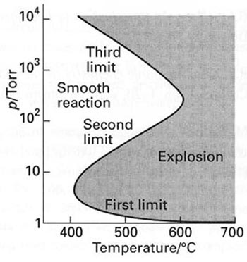
Due to high reactivity, hydrogen storage brings up some safety issues. At certain conditions, reaction between hydrogen and oxygen can lead to explosion (Figure 9.4), so storages for those gases should be separated, and leak detection is critical.
Solar hydrogen is attractive due to its carbon-free footprint, in contrast to any hydrocarbon fuels. Hydrogen has a very high energy density (142 MJ/kg), which is much higher than that of gasoline (~47 MJ/kg). This is due to its very light atomic mass. On the other side of the medal, hydrogen as a volatile gas must be contained in a compressed form, and the traditional gas cylinders used for storage and transportation of hydrogen have been a concern. Such cylinders, usually about 35 kg in weight contain only 700 g of hydrogen (at 200 bar of pressure), which is equivalent to only 2.85 liters of gasoline (Komoto et al., 2009).
The production of hydrogen via water electrolysis is most relevant to utility-scale PV systems. The efficiency of the electrolyzer is above 75% at optimized conditions. Even higher efficiencies are promised at elevated pressure, although in this case extra energy needs to be spent for isothermal compression. Much more than production, hydrogen "packaging", i.e., converting it to a convenient form for storage, can be much more costly and energy-expensive. These forms include (1) compressed hydrogen, (2) liquefied hydrogen, and (3) metal hydrides.
In option (1), compressed hydrogen is much more usable compared to that at atmospheric pressure due to much higher energy density (2.54 MJ/liter at 200 bar versus 0.0127 MJ/liter at 1 atm) (Komoto et al., 2009). Further compression to 800 bar brings its energy density to 10.1 MJ/liter - close to that of liquid hydrogen. However, multistage compression is estimated to take up to 8-12% of the total energy that hydrogen contains as fuel (referring to higher heating value), and mechanical and electrical losses can increase this value even further. Option (2), hydrogen liquefaction requires even more energy - 30 to 50 MJ/kg hydrogen converted. Option (3), metal hydrides are special compounds that can bind hydrogen by forming chemical bonds under certain temperature and pressure conditions and release hydrogen when temperature and pressure change. Simple physical pressurizing hydrogen into hydride form is possible, but is not very attractive due to the large amount of metal hydride needed (50 kg per 1 kg H2 stored) (Bossel, 2006). Chemical binding of hydrogen in metal hydrides is much more promising.
Some examples of hydride compounds are CaH2, MgH2, LiH, NaAlH4, LiAlH4. Because metal-hydrogen bonds are quite strong, energy input is needed to release hydrogen from hydride. So, temperatures for hydrogen generation need to be raised to 120-200 oC. Nevertheless, the hydride storage is theoretically more efficient. For example, if we consider the reaction
CaH2 + 2H2O => Ca(OH)2 + 2H2 - reaction of hydride with water,
we can see that by molar ratios, 42 g of CaH2 release 4 g of H2(gas), so it is roughly 4:1 ratio; at the same time, compressed storage in the cylinder provides storage of only 1 kg of hydrogen per 50 kg of storage tank, i.e., 50:1 ratio. Because of the obvious advantage of the metal hydride, substantial research effort is underway to improve this technology.
Summary and Final Tasks
Summary and Final Tasks
In this lesson, we looked at very different technologies used to store solar energy. Those technologies differ in physicochemical principles, scale, and impact, and require quite different scientific and engineering background for detailed analysis. In that sense, this material is challenging. At the same time, it is important for solar specialists to be aware of various energy storage options, as well as recent innovations, and to be able to apply those options to specific conditions. Hopefully, this lesson has been a good step in that direction and will motivate you to learn more and to elevate your expertise down the road.
Please complete the following activities to complete this lesson.
| Type | Description/Instructions | Deadline |
|---|---|---|
| Readings | Complete all necessary reading assigned in this lesson. | |
| Discussion Forum | Discussion Forum "Store or not to store"
|
Sunday night |
|
Reading Quiz |
Complete the Lesson 9 Quiz. |
Wednesday night |
References for Lesson 9
Moens and Blake, 2004, Advanced Heat Transfer and Thermal Storage Fluids, Conference Paper NREL/CP-510-37083 January 2005, National Renewable Energy Laboratory.
Wu, B., Redy, R.G., and Rogers, R.D., NOVEL IONIC LIQUID THERMAL STORAGE FOR SOLAR THERMAL ELECTRIC POWER SYSTEMS, Proceedings of Solar Forum 2001 Solar Energy: The Power to Choose April 21-25, 2001, Washington, DC.
Koning, S., Molten Salt Systems Other Applications Link to Solar Power Plants [15], Bertrams Heatec Inc. Pratteln, Switzerland, 2007.
Solar Reserve, Molten Salt Energy Storage [16], 2015.
CalFinder, Compressed air the secret to solar energy storage, [17] 2015.
D. Shriver and P. Atkins, Inorganic Chemistry, Freeman, NY, 1999.
Komoto, K., et al., Energy from the Desert, Earthscan 2009.
Bossel, U, Does a hydrogen economy make sense? Proceedings IEEE, v. 94, no. 10, pp. 1826-1837 (2006).