Continuous Catalyst Regeneration
A continuous catalyst regeneration (CCR) scheme for reforming came on stream in 1971. Figure 8.5 shows a flow diagram for the CCR process. The reactors are stacked with a moving bed of catalyst trickling from the top reactor to the bottom reactor by gravity. Partially deactivated catalyst from the bottom of the reactor stack is continuously withdrawn and transferred to the CCR regenerator. The regenerated catalyst is re-injected to the top of the first reactor to complete the catalyst circulation cycle. Hydrotreated naphtha feed is combined with recycled hydrogen gas and heat exchanged with the reactor effluent. The combined feed is then raised to the reaction temperature in the charge heater and sent to the first reactor section. Because the predominant reforming reactions are endothermic, an inter-reactor heater is used to reheat the charge to the desired reaction temperature before it is introduced to the next reactor. The effluent from the last reactor is heat exchanged with the combined feed, cooled, and separated into vapor and liquid products in a separator.
The vapor phase is rich in hydrogen gas, and a portion of the gas is compressed and recycled back to the reactors. Recycling hydrogen is necessary to suppress coking on the catalysts. The hydrogen-rich gas is compressed and charged together with the separator liquid phase to the product recovery section. The performance of the unit (i.e., steady reformate yield and quality) depends strongly on the ability of the CCR regenerator to completely regenerate the catalyst. In addition to UOP’s Platforming process, the major commercial catalytic reforming processes include PowerformingTM (ExxonMobil), UltraformingTM and MagnaformingTM (BP), Catalytic Reforming (Engelhard), Reforming (IFP), and RheniformingTM (Chevron).
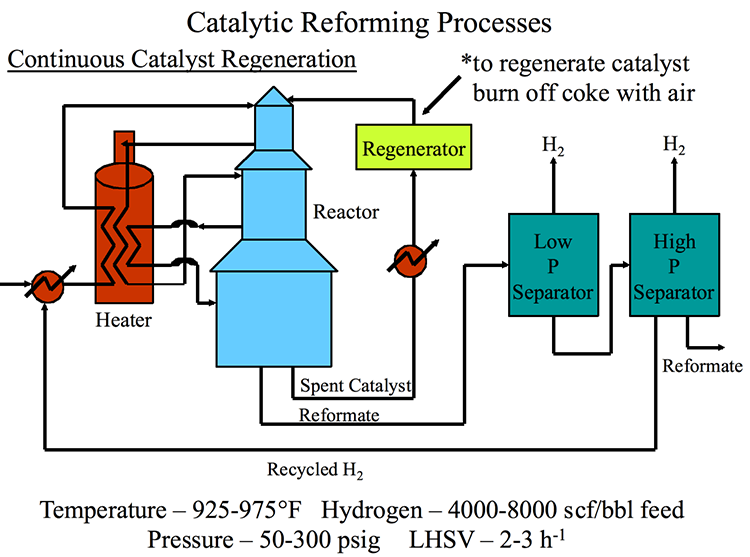
The continuous catalytic reforming process starts at the heater, which goes to the reactor. From the reactor, it can either go back to the heater or move on. The spent catalyst exits and goes to a regenerator to regenerate the catalyst and burn off coke with air. The reformate continues to a low p separator and then a high p separator. Both separators give off H2 gas. Reformate excits and recycled H2 heads back to the heater. The temperatures are 925-975*F, Hydrogen – 4000-8000 scf/bbl fee, Pressure – 50-300 psig, LHSV – 2-3/hr.