Lesson 7: Catalytic Conversion Processes Part 1
Lesson 7 Overview
Overview
Video: FSC 432 Lesson 7 (5:00)
Now this a painting in our EMS museum collections from the MS Museum collections. This is a very early refinery, I would think. You can see the oil wells here, and they're refined. The oil is refined right at the site, which is essentially distillation. You can see this must be the distillation tower. You can see the furnace here with the chimney to heat the crude to the required temperatures. And then collect the fractions.
At the time, it was kerosene, obviously, for lighting. And then, later on, maybe light gasoline. See the storage tank, maybe for the gasses and so forth. So in the last lesson, we've talked about thermal cracking processes to make more of the lighter stuff, essentially. Like distillates, or gasoline from the crude oil, by breaking chemical bonds. And we mentioned that pretty soon, the thermal cracking processes could not meet the demand for quality.
And what has changed in the meantime, when we have now close to the Second World War era, where the motors-- now engines-- have higher compression ratios, and they would require higher octane number gasoline. That means they would need gasoline that would not ignite spontaneously with pressure. And it is pressurized with air. That's essentially what the octane number measures, it's anti-knocking property.
So most catalytic processes, catalytic conversion processes, were developed right before and during the Second World War, mainly for making higher quality, higher performance fuels and in higher yields, in higher quantities. So introducing the catalyst to crack, to crude oil, into gasoline boiling range is not done just to increase the rate of cracking, or has anything to do with kinetics, really. That's what catalysts typically do.
In this case, introduction of the catalyst changes the whole chemistry of cracking. Now we've talked about having neutral, reactive species free of radicals and thermal cracking processes. In catalytic cracking, the reactive species are ions. Or cations, actually, cargo cations that are produced on catalyst surfaces. So we need an acid catalyst-- typically aluminum, silica or zeolites-- in order to create these cationic species.
Why do we need that? Because carbo cations go through isomerization reactions very fast. That means we will have now an opportunity to make branched alkanes or isoparaffins because of this isomerization of the ions as opposed to non-isomerization of the free radicals. Isomerization in free radicals is very, very slow. So it doesn't happen.
So pretty much all gasoline production in the US is done through catalytic means. Fluid catalytic cracking is really the most popular processes. It is the heart of a refinery in the United States, FCC process that generates high octane gasoline. It's a very flexible process. It could use a range of feed stocks in the gas oil, boiling range all the way up to light vacuum gas oil.
For heavier materials, something like heavy vacuum gas oil or vacuum distillation residue, we need to introduce hydrogen so that we could convert these heavy fractions without rejecting larger quantities, or very large quantities, of carbon. Then we get into a hydro cracking processes.
So in this lesson we will go over the historical development of catalytic cracking processes, ending up of course with FCC-- which is universally used and accepted now-- and talk about the hydra cracking processes, some of the conditions that are necessary for treating those very heavy ends of crude oil into upgraded products without rejected carbon, so in higher yields.
Overview
Catalytic conversion processes became important in petroleum refining after the Second World War. Catalytic cracking has been developed to produce high yields of gasoline with high octane # from high-boiling stocks using catalysts. As different from thermal cracking, catalytic cracking.
- uses a catalyst;
- takes place at lower temperature and lower pressure;
- is more selective and flexible.
One particular catalytic cracking process, Fluid Catalytic Cracking (FCC), has captured universal acceptance in the refining industry because of its feed flexibility, ability to modify product yields through minor changes in the process operating conditions. FCC is used to produce high-octane gasoline mainly from straight-run atmospheric gas oil and light vacuum gas oil (LVGO) [1]. This process involves breaking up long chains of n-alkanes into shorter chains of branched alkanes (isoalkanes), cycloalkanes (naphthenes), and aromatics by using acidic catalysts. In addition to high-octane gasoline, catalytic cracking produces LPG, cycle oils, and olefin-rich light hydrocarbons (C3, C4). The olefins are used as petrochemical feedstocks, or as reactants in alkylation and polymerization reactions, to produce higher molecular weight branched alkanes and olefins to contribute to the high-octane gasoline pool.
Hydrocracking processes have been introduced for upgrading heavier crude oil fractions such as heavy vacuum gas oil (HVGO) and vacuum distillation residue VDR. The heaviest fractions of crude oil, HVGO and VDR, may not be easily processed by FCC because of potential problems with excessive coking on the catalysts. For upgrading these high-boiling and aromatic-rich feedstocks, hydrogen is introduced in the hydrocracking process, along with bi-functional catalysts systems, to keep coking under control while upgrading the heavy fractions to light and middle distillates.
Learning Outcomes
By the end of this lesson, you should be able to:
- distinguish the chemistry of catalytic cracking from chemistry of thermal cracking and illustrate the formation of carbocations and IUPAC terminology for classification of carbocations;
- categorize the formation of different carbocations on active sites of cracking catalysts and assess the classification of acid sites (Lewis vs Bronsted) on catalyst surfaces;
- compare, with examples, how the product yields and composition obtained from catalytic differ from those from thermal cracking;
- analyze the thermodynamics of carbocation formation and evaluate how ionic chain reactions produce hydrocarbons with high octane numbers;
- appraise the historical evolution of catalytic cracking processes and formulate the driving forces that have shaped this evolution in reactor design and catalyst development;
- locate the hydrocracking process and hydroprocessing in the refinery flow diagram, illustrate hydrocracking processes and evaluate different process objectives.
What is due for Lesson 7?
This lesson will take us less than one week to complete. Please refer to the Course Syllabus for specific time frames and due dates. Specific directions for the assignments below can be found on the Assignments page within this lesson.
| Readings | J. H. Gary, G. E. Handwerk, Mark J. Kaiser, Chapters 7 (Catalytic Hydrocracking) and Chapter 8 (Hydroprocessing and Resid Processing) |
|---|---|
| Assignments | Exercise 6 Quiz 3. Will cover material in Lessons 6 and 7. Check the Syllabus, or Course Calendar for Quiz 3 schedule. |
Questions?
If you have any questions, please post them to our Help Discussion (not email), located in Canvas. I will check that discussion forum daily to respond. While you are there, feel free to post your own responses if you, too, are able to help out a classmate.
Chemistry of Catalytic Cracking
Chemistry of Catalytic Cracking
As opposed to thermal cracking governed by free radicals, catalytic cracking proceeds through the formation of ionic species on catalyst surfaces, and produces shorter, but branched-chain (not straight-chain) alkanes by cracking the long straight-chain alkanes. The formation of branched-chain alkanes, or iso-alkanes, leads to the production of gasoline with high octane numbers. This is the fundamental reason why catalytic cracking has replaced thermal cracking as the central process in a refinery geared to maximize gasoline production. A high octane number of gasoline is needed for current spark-ignition engines to run at high compression ratios without knocking. High compression ratios in spark-ignition engines translate to high power and high efficiency.
Figure 7.1 introduces the two types of ionic species, carbocations, that are active in catalytic cracking reactions as carbenium, and carbonium ions, using the IUPAC terminology. Carbocations are the positively charged ions made from hydrocarbons. Figure 7.1 shows that removing a hydride ion (H-, a hydrogen atom with an additional electron) from an alkane (e.g., methane) produces carbenium ions (path 1a). Also, adding a proton (H+, a hydrogen atom without the electron) to an olefin (e.g., ethylene) can produce carbenium ions, as shown in path 1b.
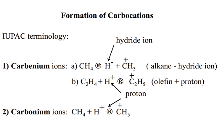
Formation of Carbocations
IUPAC terminology
-Carbenium ions: CH4 (arrow) H- + CH3+ (alkane – hydride ion)
-C2H4 + H+ (arrow) C2H5+. (olefin + proton)
-Carbonium Ions: CH4 + H+ (arrow) CH4
KEY: H- (hydride ion), H+ (proton)
Analogous to the terminology used for free radicals, C+H3 is called methyl carbenium ion, and C2+H5 is called an ethyl carbenium ion. Carbonium ions are produced by adding a proton to an alkane, say methane, as shown in Figure 7.1. The resulting ion C+H5 is called methanium. Note that there is some confusion in the literature about naming the carbocations. Carbenium ions used to be called carbonium ions in some sources, including your textbook [2]. All references to carbonium ions in Section 6.3 Cracking Reactions in the textbook should be corrected as carbenium ions.
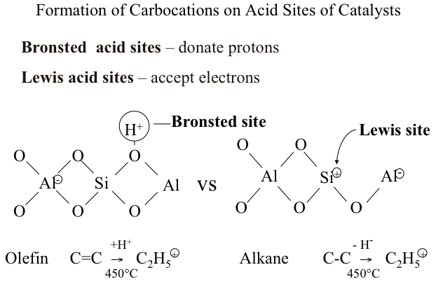
Bronsted and Lewis Acid Sites
Carbocations are formed from hydrocarbons on two different acid sites: Bronsted acid sites and Lewis acid sites. You should remember that Bronsted acid sites donate protons, while Lewis acid sites accept electrons to form carbocations from hydrocarbons. Figure 7.2 illustrates how an olefin (e.g., ethylene, C=C) produces an ethyl carbenium ion (C+2H5) by reacting with a proton donated from Bronsted acid site. Alternatively, also seen in Figure 7.2, a Lewis acid site accepts an electron (or a hydride ion, H-) from an alkane (e.g., ethane, C-C) to produce the same ethyl carbenium ion (C+2H5). These two reactions that take place on the acid sites of catalysts, along with the formation of carbonium ions by protonation of hydrocarbons on Bronsted sites, function as the initiation steps in the ionic chain reactions that lead to the products obtained from catalytic cracking.
Distribution of Products
Distribution of Products
Figure 7.3 compares the distribution of products from thermal cracking (free radical chain reactions) and catalytic cracking (ionic chain reactions). Short chain paraffins constitute the principal products in both cases, with one important difference – an abundance of iso-alkanes (branched-chain alkanes) in catalytic cracking products. One can also note in Figure 7.3 that catalytic cracking products contain higher concentration of aromatic compounds. High octane number of gasoline produced by catalytic cracking can be attributed to high concentrations of i-alkanes and relatively more abundant aromatics present in the crackate (catalytic cracking product). Having no olefins larger than butylene (C4) from catalytic cracking processes, also distinguishes catalytic cracking products from thermal cracking products obtained from gas oil.
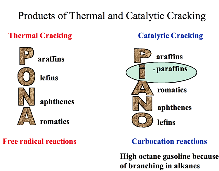
Products of Thermal and Catalytic Cracking
Thermal Cracking – Free radical reactions
P araffins
O lefins
N aphthenes
A romatics
Catalytic Cracking – Carbocation reaction
High octane gasoline because of branching in alkanes
P araffins
I -paraffins
A romatics
N aphthenes
O lefins
Comparison of Products by Type of Hydrocarbon
Comparison of Products by Type of Hydrocarbon
Table 7.1 compares the products of thermal cracking and catalytic cracking of different type of hydrocarbons. Notably, high yields of C1 and C2 gaseous products (methane, ethane, and ethylene) from thermal cracking are contrasted with high yields of C3- C6, with small quantities of methane and essentially no olefins heavier than butylene, from catalytic cracking. Significant for the octane number of the gasoline fraction from the catalytic cracking of aliphatic hydrocarbons are the abundance of i-alkanes and significant concentration of aromatic compounds (BTX) that increase the octane number.
| Hydrocarbons | Thermal Cracking | Catalytic Cracking |
|---|---|---|
| n-alkanes (e.g., C16) |
C2is major product C1in large quantities C4-C15olefins in moderate abundance |
C3-C6are major light prods C1in small quantities No olefins > C4 |
| Aliphatic |
Little aromatization at 500ºC No branched – chain alkanes present |
Significant aromatization Abundance of branched – chain alkanes |
| n-0lefins |
Slow double bond isomerization Little skeletal isomerization |
Rapid isomerization C=C–C–C→ C–C=C–C Rapid skeletal isomerization |
| Alkylaromatics | ß – scission | |
| Naphthenes | Crack more slowly than n-paraffins | Crack at comparable rates with n-paraffins |
As discussed in Lesson 6, the slow isomerization of free radicals (moving the unpaired electron from an edge atom to the interior atoms) results in the production of shorter straight-chain alkanes and straight-chain olefins in thermal cracking, thus leading to low octane numbers of the gasoline product. In contrast to free radicals, the isomerization of carbocations is very fast because of the thermodynamic driving force, shown in Table 7.2. One can see in Table 7.2 that the isomerization of a primary propyl carbenium ion to a secondary propyl carbenium ion releases (19.1- 1.5) = 17.6 kcal/mol. This is a very large thermodynamic driving force for the isomerization of a primary ion to a secondary ion, and further to a tertiary ion, with even a larger driving force. Isomerization of the secondary propyl ion to the tertiary propyl ion, releases 1.5 kcal/mol of energy. It is, therefore, clear that the initiation and propagation of carbocations in catalytic cracking chain reactions on the catalyst surfaces will be dominated by the formation of secondary and tertiary carbocations. The reactions of these carbocations lead to the formation of branched-chain alkanes and olefins with high octane numbers.
| Carbenium Ions | ΔHf(relative) (kcal/mol) |
|---|---|
|
C1+ primary |
19.1 |
|
C2+ secondary |
1.5 |
|
C3+ tertiary |
0 |
Another important feature of carbocation formation is the differences in the enthalpy of formation which favors the formation of carbocations > C3 versus C1 and C2 ions (Table 7.3), because C1 and C2 ions are primary ions. This explains the low yields of C1 and C2 species obtained from catalytic cracking.
| Carbenium Ions | ΔHf(relative) (kcal/mol) |
|---|---|
| CH3⊕ | 258 |
| C2H5⊕ | 225 |
| n-C3H7⊕ | 218 |
| i-C3H7⊕ | 198 |
| n-C4H9⊕primary | 211 |
| t-C4H9⊕ tertiary | 174 |
Ionic Chain Reactions
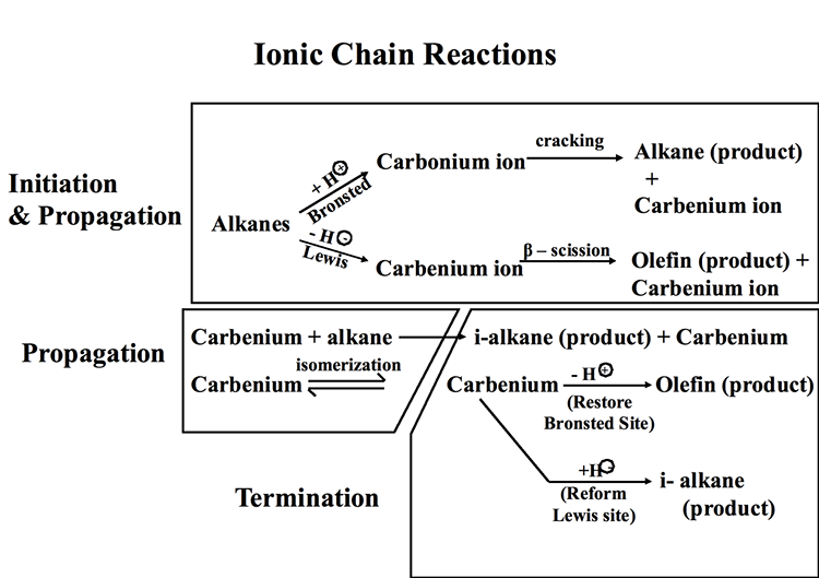
Ionic Chain Reactions
Figure 7.4 illustrates the ionic chain reactions that govern catalytic cracking of hydrocarbons. The initiation step includes the formation of a carbonium ion by proton donation from a Bronsted acid site and/or the formation of a carbenium ion through hydride ion abstraction by a Lewis acid site. In a propagation step, the carbonium ion goes through cracking to produce an alkane product and a carbenium ion, while the carbenium ion produced on the Lewis acid site goes through a β-scission to produce an olefin product and another carbenium ion. In additional propagation reactions, carbenium ions (secondary, or tertiary) react with alkanes to produce i-alkane products and other carbenium ions, which can go through isomerization reactions generating more stable ions. Finally, in termination steps, carbenium ions donate a proton to restore a Bronsted acid site and produce an olefin as final product, or they abstract a hydride ion to restore a Lewis acid site producing an i-alkane product, and the ionic chain reaction continues. Other reactions during catalytic cracking include dehydrocyclization and dehydrogenation reactions to produce aromatic compounds. One should note that thermal cracking reactions also take place during catalytic cracking because of the sufficiently high temperatures used in the process. Some claim that initial thermal cracking of alkanes to produce olefins should also be considered as an initiation step in ionic chain reactions [2].
Catalytic Cracking Processes
Catalytic Cracking Processes
Increasing demand for gasoline, along with the need to produce high-octane gasoline for increasingly more powerful spark ignition engines, led to the development and maturation of catalytic cracking processes just before and during World War II. Following the development of a fixed-bed (Houdry process, 1936) and a moving-bed (Thermafor Catalytic Cracking, 1941) catalytic cracking process, fluid-bed catalytic cracking (FCC, 1942) became the most widely used process worldwide because of the improved thermal efficiency of the process and the high product selectivity achieved, particularly after the introduction of crystalline zeolites as catalysts in the 1960s.
The list below shows a timeline for the development of the catalytic cracking processes. The evolution of catalytic cracking processes is an exemplary showcase in chemical engineering for discussing the advancement of reactor configuration, driven by energy conservation and process kinetics. The evolution of these processes is discussed in the following subsections.
Historical Time-Line for Catalytic Cracking Processes
-
McAfee (1915)
-
Batch reactor catalytic cracking to produce light distillates
-
Catalyst: A1Cl3 – A Lewis acid, electron acceptor
-
Alkane – electron(abstracted by A1Cl3)→ a carbocation(+)→ ionic chain reactions to crack long chains
-
-
Houdry (1936) - a commercial process
-
Continuous feedstock flow with multiple fixed-bed reactors
-
Cracking/catalyst regeneration cycles
-
Catalyst: clays, natural alumina/silica particles
-
-
Thermafor Catalytic Cracking (TCC) (1942)
-
Continues feedstock flow with moving-bed catalysts
-
Catalyst: synthetic alumina/silica particles
-
Higher thermal efficiency by process integration
-
-
Fluid Catalytic Cracking (FCC) (1942)
-
Continuous feedstock flow with fluidized-bed catalysts
-
Catalyst: synthetic alumina/silica+zeolites (1965)
-
Houdry Catalytic Cracking
Houdry Catalytic Cracking
The first catalytic cracking process was developed as a batch process (McAfee, 1915) shortly after the development of a thermal cracking process. The process used Lewis acid catalysts (e.g., AlCl3) for cracking. These catalysts were expensive and corrosive. In addition to these impediments, use of a batch reactor in the McAfee process did not allow large-scale commercialization of this process. The first full-scale commercial process, the Houdry Catalytic Cracking, used much less expensive catalysts, such as clays, and natural alumina and silica particles. Figure 7.5 shows the configuration of the Houdry Catalytic Cracking process. For cracking, gas oil feed was heated to 800°F and fed to a fixed-bed reactor packed with the catalyst particles. Cracking products are sent to a fractionator to be separated into gas, gasoline, light cycle oil (LCO) and heavy cycle oil (HCO) products.
Video: Houdry Catalytic Cracking (5:03)
INSTRUCTOR: As I mentioned before, the evolution of catalytic cracking processes is really a good example of process engineering or reactor design to maximize the thermal efficiency of a process. The first cat cracking process was a batch process introduced in 1915, the McAfee process, from a Lewis acid. Aluminum chloride was used in the batch reactor system. But for commercial operation, you would need a floor reactor system. So Houdry cat cracking was the first commercial continuous process introduced in 1936.
The process used the natural aluminum silica solids particles as catalysts. And in the process, we're going to look at a configuration that has three reactors in parallel. These are fixed bed reactors essentially filled with the alumina silica pellets, packed with the alumina silica palettes as catalysts. So the gas oil feed is heated in a furnace, in a fired furnace to 800 degrees Fahrenheit, and the feed is fed from the bottom of this packed bed to go through cracking on catalyst surfaces, and the products are fed to a fractionater. In the fractionater, the products are separated into gas and gasoline and LCO, light cycle oil, as the major products from cat cracking.
As the cracking goes on, the catalysts are deactivated by coke buildup. And this happens pretty fast, within 10 minutes of the introduction of the feed into the reactor. Now, since this is an endothermic reaction, you would also imagine or could visualize that the temperature will go down as the feed moves from the bottom to the top of the reactor. So cracking isn't really very homogeneous because of this decreasing temperature.
Now, once the catalysts are deactivated within 10 minutes, all coked up, you bring in steam to strip the liquids, somewhat heavier liquids that are sticking onto the catalyst surfaces to remove them into the fractionater. And some of this will end up as heavy oil. Once this operation is finished, within about five minutes, then you bring in hot air to burn off the coke to reactivate the catalyst.
But to continue this cracking process in the meantime, while you are stripping the heavier products and reactivating the customers by burning the coke, you need to switch the feed to another reactor. So that is the second in the series. So you have a continuous feed and continuous production through the system using the swing reactor configuration, as we refer to.
The same thing happens in the second reactor. The catalyst is deactivated within 10 minutes, so you bring in the steam to strip the heavier products. And while you're doing that, obviously, and then later on, burning off the coke, you should switch the feed to another reactor. That would be the third reactor in these areas. And the products are all sent to a fractionater.
So by the time the third reactor is coked up, you can now switch the feed back to the first reactor. You will have enough time to steam strip and coke or decoke the first reactor, having these additional two reactors in the series. So that's essentially the cycle in the Houdry cat cracking reaction to enable a continuous flow system while the reactors are taken out of service for decoking operations.
You see the problem here. The endothermic reaction of cracking is decoupled, really, from the exothermic reaction of burning of the coke. So for that reason, the thermal efficiency of Houdry cat cracking is not very high, and it certainly needs to be improved.
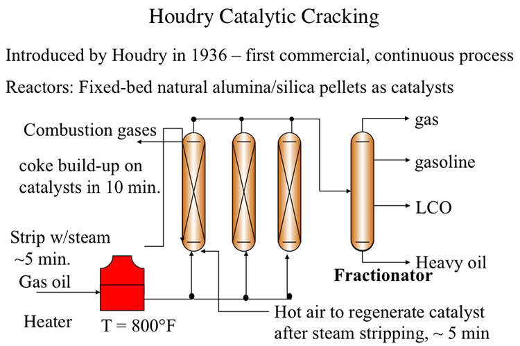
A series of swing reactors were needed to switch the feed flow from one reactor to another after approximately 10 minutes of operation. The switch to a swing reactor was necessary because of rapid coking on catalysts which, being natural materials, had a wide range of activity. Rapid coking on silica/alumina particles deactivated these catalysts and led to plugging of the reactors. After the flow was switched to another reactor, the isolated reactor was stripped with steam for five minutes to remove the liquid products adsorbed on catalyst particles. After stripping with steam, the deactivated catalysts were regenerated by burning off the coke on catalysts with hot air introduced to the reactor. Catalyst regeneration also takes approximately 5 minutes before the reactor with regenerated catalyst is ready to accept the feed again. By this time, the second reactor would be ready for the 10-minute cycle of steam stripping and catalyst regeneration. Having a third reactor in the plant would help deal with any delays/problems in reactor preparation. Considering that catalytic cracking is an endothermic process, the heat generated from burning the coke off the catalyst could be used partially to heat the catalyst particles for the endothermic reaction. A large portion of the heat in the flue gases from coke combustion was not available for the process. Therefore, the thermal efficiency of the Houdry Process was low.
Thermafor Catalytic Cracking (TCC)
Thermafor Catalytic Cracking (TCC)
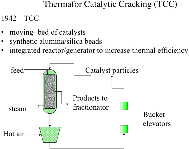
Thermafor (also referred to as “thermofor” in some sources) Cracking Process was introduced for better integration of thermochemistry (endothermic cracking and exothermic catalyst regeneration) by introducing a moving-bed configuration, rather than a fixed-bed, as shown in Figure 7.6. Catalysts used in this process were synthetic alumina/silica beads that have more homogeneous and consistent properties (e.g., activity) than the natural minerals. Catalysts particles and the feed are introduced from the top of the reactor, and the catalyst particles move downward with gravity as the cracking reactions take place on the catalyst surfaces. Steam is injected from the bottom of the reactor to carry the cracking products to the fractionator for recovery. As the particles move down the reactor, they are deactivated by coke build-up on active sites. The deactivated catalysts removed from the bottom of the reactor are sent to a regenerator unit where the coke on catalysts surfaces are burned off and the heated catalysts particles are recycled to the top of the reactors by bucket elevators. Hot catalyst particles provide most of the heat necessary for the cracking reactions in the reactor. Although the thermal efficiency of TCC is higher than that of the Houdry process, there was still a significant amount of heat loss during the transport of heated catalyst particles by bucket elevators.
Video: Thermafor (3:53)
Thermafor catalytic cracking process provided significant improvement over the Houdry cat cracking in terms of the thermal efficiency. Now, this improvement came with the change in the reactor configuration from a fixed bed in Houdry to a moving bed of catalyst now. So the catalysts are not fixed, but they are moving by gravity so that the reaction can be now conducted in just one reactor instead of having multiple reactors and switching between those reactors.
There was an improvement in the catalyst as well. Instead of using natural silica-alumina, now there are synthetic alumina-silica beads with more controlled activity, more homogeneous activity of the sites that the cracking goes on, which, of course, makes the control of the reactions better compared to the Houdry cat cracking.
So the integration of the reactor and the catalyst regenerators, as you will see, has increased the thermal efficiency very significantly over the fixed bed, the Houdry cat cracking.
Now, you can see that the feed is introduced along with the catalyst from the top of the reactors. So the particles move down with gravity at controlled flow rates along with the feed. So as the cracking goes on, on the catalyst surfaces, there is the activation. There's still coking going on, on the catalyst particles. So by the time they reach the bottom of the reactor flowing with gravity, the catalyst reactivity has been reduced to a significant extent. The catalysts are now ready to be reactivated or regenerated.
Steam, as you can see, is introduced from the bottom of the reactor to strip off all the volatile products during cracking, and the products are sent to a fractionator for separating into gas, gasoline, LCO, heavy oil, and so forth.
So the used catalysts, then, leaving the reactor is sent to a furnace where hot air is introduced to burn off the coke on the surface of the catalyst to regenerate the active sites. And the regenerated catalysts, the hot particles now, are put on bucket elevators to be sent up to the top of the reactor to close the catalyst cycles.
So the thermal integration here is such that the heat that is generated by burning the coke heats the catalyst particles. And these are hot enough to actually have the cracking take place on the surface. You can see that there is no external heater in this reactor scheme in Thermafor Cat Cracking.
But there is still more heat losses, especially in this bucket elevator system, transporting the hot catalyst particles to the top of the reactor. Thermal efficiency, although much improved over the Houdry fixed bed process, there is still a lot of room for improvement in thermal efficiency through the integration of endothermic and exothermic reactions.
Fluid Catalytic Cracking (FCC)
Fluid Catalytic Cracking (FCC)
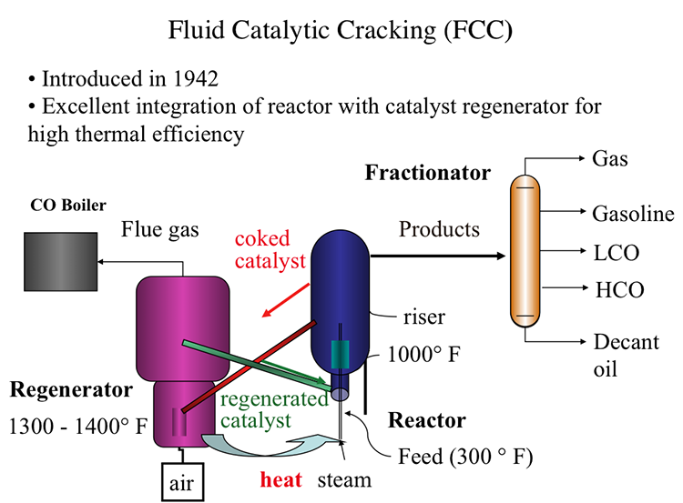
Fluid Catalytic Process, also introduced in 1942, offered an excellent integration of the cracking reactor and the catalyst regenerator that provides the highest thermal efficiency, as shown in Figure 7.7. In FCC, a fluidized-bed (or fluid-bed) of catalyst particles is brought into contact with the gas oil feed along with injected steam at the entrance (called the riser) of the reactor. The hot catalyst particles coming from the regenerator unit evaporate the feed gas oil upon contact in the riser, and the cracking starts as the gas oil vapors and the catalyst particles move upward in the reactor. The temperature of the catalyst particles drops as the evaporation of gas oil and endothermic cracking reactions proceed during the upward movement. Cracking reactions also deposit a significant amount of coke on the catalysts, leading to the deactivation of the catalyst. After removing the adsorbed hydrocarbons by steam stripping, the coked catalyst is sent to the regeneration unit to burn off the coke with air. Heat released from burning the coke deposit increases the temperature of the catalyst particles that are returned to the riser to complete the cycle. Burning off the rejected carbon (coke) in the regenerator provides the energy necessary for cracking without much loss, thus increasing the thermal efficiency of the process. The cracking products are sent to the fractionator for recovery after they are separated from the catalyst particles in the upper section of the reactor [3].
In the reactor, the cracking reactions initiate on the active sites of the catalysts with the formation of carbocations and the subsequent ionic chain reactions produce branched alkanes and aromatic compounds to constitute the crackate (cracked gasoline with high octane number), light olefins, cycle oils, and slurry oil that are sent to the fractionator. A carbon-rich byproduct of catalytic cracking, termed “coke,” deposits on catalyst surfaces and blocks the active sites. FCC is considered a carbon rejection process because the coke deposited on the catalyst surface and eventually burned off for heat is rich in carbon and thus enables the production of large quantities of a light distillate (crackate) in the process without the addition of hydrogen.
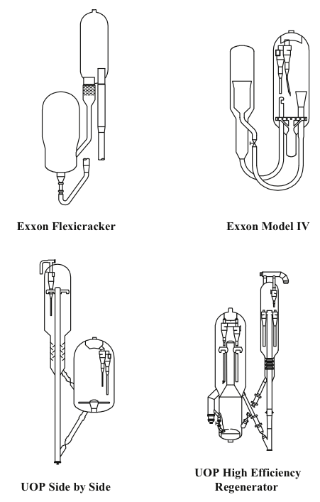
Two different configurations of the commercial FCC processes exist depending on the positions of the reactor and the regenerator: they can be side by side or stacked, where the reactor is mounted on top of the regenerator. Major licensor companies that offer FCC processes with different configurations include Kellogg Brown & Root, CB&I Lummus, ExxonMobil Research and Engineering, Shell Global Solutions International, Stone & Webster Engineering Corporation, Institut Francais du Petrole (IFP), and UOP. Figure 7.8 shows examples of Exxon and UOP designs [1,4]. The UOP design of high-efficiency two-stage regenerator units offer advantages of uniform coke burn, higher conversion of CO to CO2 and lower NOx emissions among others. Another modification to FCC plants could be the installation of a catalyst cooler, which may provide better control of the catalyst/oil ratio; the ability to optimize the FCC operating conditions, increase conversions, and process heavier residual feedstocks; and better catalyst activity and catalyst maintenance [3].
In the first video below, the animation of an explosion in an FCC unit in 2015 (7:12 minute long) provides a good review of the FCC process, and points out the potential hazards of working with hydrocarbons exposed to high temperatures in refinery units:
2015 Explosion at ExxonMobil Refinery (7:12)
SPEAKER: The Torrance refinery is a 750-acre facility located just outside of Los Angeles, California. At the time of the explosion, the refinery was owned by ExxonMobil. An important part of the refining process takes place in the facility's fluid catalytic cracker or FCC unit. In the FCC unit, heavy hydrocarbons from crude oil are broken or cracked into smaller hydrocarbons, which can then be processed into gasoline and other fuel products.
The heavy hydrocarbons are first fed into a reactor where they mix with a catalyst. The heavy liquid hydrocarbons are converted into lighter hydrocarbon vapors as they travel up the reactor. At the top of the reactor, the lighter hydrocarbon vapors are separated from the catalyst. The hydrocarbon vapors then flow to the main distillation column.
The catalyst falls down the side of the reactor, where it moves through a slide valve to a piece of equipment called the regenerator. During the reaction, a layer of carbon called coke forms on the catalyst that must be removed. Inside the regenerator, air is added, and the coke on the catalyst is burned off. The catalyst is then fed back to the reactor through a slide valve, and the cycle is repeated.
When the coke is burned off the catalyst, this creates products of combustion called flue gas. The flue gas flows out the regenerator and enters a system comprised of multiple pieces of equipment which remove any remaining catalyst particles present. The regenerator and flue gas system comprise the air side of the FCC unit.
The last piece of equipment in the flue gas system is called the electrostatic precipitator or ESP. The ESP removes small catalyst particles using static electricity. While the ESP is energized, it creates sparks, which are sources of ignition.
It is critical that the flammable hydrocarbons in the reactor do not flow into the air side of the FCC unit as this could create an explosive atmosphere. To avoid this hazard, the two slide valves connecting the reactor and regenerator are used to maintain a catalyst barrier between the pieces of equipment.
The sequence of events that eventually lead to the explosion at the refinery began on Monday, February 16, 2015, when a piece of equipment in the air side of the FCC unit called the expander vibrated forcefully enough that the refinery's control system automatically transitioned the FCC unit to a standby mode known as safe park.
During safe park mode, the flow of hydrocarbons into the reactor is turned off. The flow of air into the regenerator is also stopped. The two slide valves connecting the reactor and regenerator are closed to ensure a catalyst barrier is maintained. Steam is then forced into the reactor to prevent hydrocarbons in the main distillation column from flowing back inside.
The ESP remains energized during safe park. One slide valve however had eroded over six years of operation. And even though it closed, it could not maintain a catalyst barrier in the reactor. Within seven minutes of the unit going into safe park, all of the catalyst in the reactor fell through the slide valve into the regenerator.
A direct pathway was created for hydrocarbons to flow between the reactor and the regenerator. But the pressure of the steam flowing into the reactor as part of safe park mode was high enough to prevent hydrocarbons in the main column from flowing back inside.
With the unit in safe park mode, operators attempted to restart the expander several times but were unable to do so. Refinery personnel met to identify a strategy to repair the expander and bring the FCC unit back on line. Operations personnel predicted the expander could not restart because catalyst had likely accumulated inside.
On Tuesday, February 17, a meeting took place involving a group of refinery personnel. The group discussed a similar expander outage that occurred in 2012 for which the refinery had developed what is called a variance.
A variance is a management-approved deviation from procedure. The group decided to use the 2012 variance, which allowed a departure from the typical requirements for isolating the expander. Part of that process involved installing a blind in one of the expander's outlet flanges.
On the morning of Wednesday, February 18, Exxon Mobil maintenance attempted to install that blind but were unable to do so because steam was escaping through the open flange. Steam from the reactor had traveled through the leaking slide valve into the air side of the FCC unit.
Using the variance as a guide, the flow of steam into the reactor was decreased in an attempt to reduce the amount escaping from the expander. But the variance did not evaluate whether this flow rate was sufficient to prevent hydrocarbons from flowing into the reactor from the main distillation column.
And unknown to the operators, light hydrocarbons from a separate unit had flowed through a leaking heat exchanger into the main column, increasing pressure inside. With the flow of steam reduced and less pressure in the reactor, nothing could prevent the hydrocarbons from flowing back from the main distillation column. The hydrocarbons flowed into the reactor, where they escaped through the leaking slide valve into the air side of the FCC unit.
At 8:07 AM, a maintenance supervisor working in the FCC unit received an alarm on his personal hydrogen sulfide monitor warning him that hydrocarbons were leaking nearby. By 8:40 AM, multiple workers around the expander received the same alarm, and the FCC was evacuated.
In an attempt to mitigate the problem, a supervisor ordered the flow of steam to the reactor to be increased, but it was too late. A flammable hydrocarbon mixture was flowing through the air side of the FCC unit and moving toward the ESP with its multiple ignition sources. There the flammable hydrocarbon mixture violently exploded.
Video: Fluid Catalytic Cracking (5:08)
Fluid catalytic cracking, or FCC, is the last step in the evolution of cat cracking processes-- also introduced in 1942, just like TCC or Thermafor Cat Cracking, during the Second World War in an effort to make high-octane number gasoline. Remember that high-octane number relates to high power as you can have higher compression ratios in the combustion engines.
FCC really shows an excellent integration of the cracking reactor, an endothermic reactor, with the catalyst regenerator and exothermic reactor for very high thermal efficiency. FCC is now used universally in oil refineries throughout the world-- has replaced all the previous cat cracking processes.
Now, in FCC, in the feed, that is gas oil preheated to about 300 degrees Fahrenheit-- is introduced into the reactor with steam. The riser part of the reactor where the hot catalyst particles-- as you see, the green line coming from the catalyst regenerator-- are full of dyes. The particles are full of dyes because they're smaller particles. They are full of dyes and flowing gases and vapors. So they have a huge surface area to meet the incoming feed at temperatures that are close to 1,000 degrees Fahrenheit.
So cracking reactions on these very fine particles that are full of dyes and flowing with the reactants takes place in a very short space of time, something that could be measured with seconds. And the products are sent to a fractionator after going through a series of cyclones, obviously, to separate the small fluid dyes, the particles of the catalyst.
In the fractionators, the products, as usual, are separated into gas, gasoline, light cycle oil, heavy cycle oil, and, finally, the heaviest fractions, decant oil.
Remember that LCO is used in the US for making diesel fuel through hydrocracking and hydrogenation. And decant oil could be used as fuel oil or as feedstock for making carbon black or white coking to make needle coke for graphites, electrodes.
Coming back to the reactors, the cat cracking reactor, the coked catalyst now, the end of the riser where this cracking reaction takes place, are sent through the regenerator. It's not fully coked on the surface, lost its activity. Through the red line, it's sent to the regenerator where air is introduced to burn off the coke.
The temperatures in the regenerator could reach to 1,300 to 1,400 degrees Fahrenheit. You should remember that the catalysts now are much improved, as well. It may include zeolites that would take high temperatures and very controlled reactivities through pore size distribution and so forth.
So the combustion products or flue gases from this catalyst regenerator could be sent to a CO boiler because the gas may contain significant amount of carbon monoxide, which could be burned to CO2 to provide additional heat or to generate additional heat.
So the catalysts that are now regenerated are sent to the reactor to close the catalyst cycle through that green line, as you see, to meet the incoming feed. So our catalyst cycle is pretty much complete at this point.
But note this excellent integration, thermal integration, of the catalyst regeneration, the exothermic process, with the cracking reactions where the catalysts that are heated in the regenerator are sent in a very effective manner to the reactor without much heat loss. So that is the ultimate, if you will, thermal efficiency of a process. And that's why FCC is now the universally accepted catalytic cracking process.
Zeolite Catalysts
Zeolite Catalysts
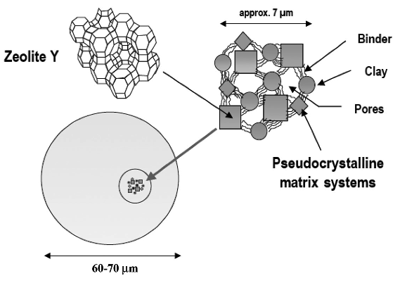
One of the significant developments in FCC practice was the introduction of zeolite catalysts in 1965. Catalysts and additives play a major role in the selectivity and flexibility of FCC processes. FCC catalyst consists of a fine powder with an average particle size of 60–75 μm and a size distribution ranging from 20 to 120 μm. Four major components make up the catalysts: zeolite, active matrix, filler, and binder. Each of these constituents has a unique role to play, but zeolite is the key component that is more active and selective for high-octane number gasoline production [4]. Table 7.4 compares the octane numbers of some refinery products and FCC gasoline.
| Product |
RON (600 rpm) |
MON (900 rpm) |
|---|---|---|
| Regular - Premium Gasoline | 90-100 | 80-90 |
| Straight Run Gasoline | 60-68 | 60-68 |
| FCC Gasoline (light) | 93 | 82 |
| FCC Gasoline (heavy) | 95 | 85 |
Exercise 8
Exercise 8
Solve a problem on the material balance for the regenerator in Fluid Catalytic Cracking Process.
Material Balance for FCC Regenerator Problem
Burning the coke deposited on the catalyst particles generates all the heat necessary for catalytic cracking. Therefore, the coke burning rate is a critical parameter to control the rate of cracking. The composition of dry flue gas from the regenerator of an FCC unit is given in vol% as follows:
N2: 81.6
CO2:15.7
CO: 1.5
O2: 1.2
The dry air flow rate to the regenerator is given as 593 SCMM (standard cubic meters per minute). Considering that a significant portion of coke is carbon, calculate the carbon burning rate in the regenerator in kg/min. Remember: 1 kgmole at STP = 22.4 m3)
Catalytic Hydrocracking
Catalytic Hydrocracking
Catalytic hydrocracking is one of the latest additions to petroleum refining processes, with the first modern commercial unit started up by Chevron in 1958. The interest in hydrocracking has been attributed to the increasing demand for light and middle distillates, the availability of byproduct hydrogen in large quantities from catalytic reforming, and the environmental regulations limiting sulfur and aromatic hydrocarbons in motor fuels [5]. The advantages of hydrocracking include its ability to handle a wide range of feedstocks that may be difficult to process by catalytic cracking and its flexibility in selectivity between light and middle distillates. The principal objective of hydrocracking is to decrease the molecular weight and boiling point of heavy oils to produce saturated hydrocarbons (diesel and jet fuel) from highly aromatic feedstocks (e.g., LCO from FCC) and distillation residua.
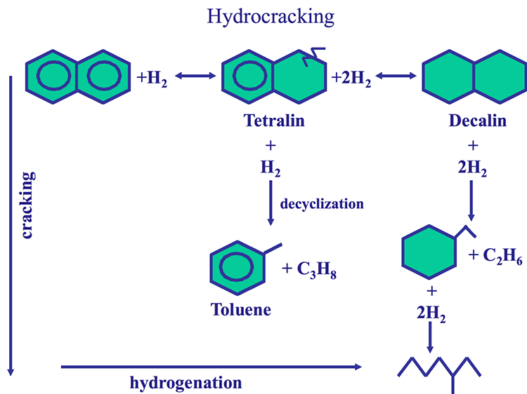
The hydrocracking process has two dimensions: Hydrogenation of aromatic rings and cracking of aliphatic compounds, as shown in Figure 7.10, using naphthalene as an example for an aromatic ring system. One should note that the aromatic rings cannot be cracked before they are saturated with hydrogen. With hydrocracking, it is possible to convert an aromatic compound to a paraffinic compound without any loss of carbon, as shown in Figure 7.10. As a hydrogen-addition process, hydrocracking provides high yields of valuable distillates without producing low-grade byproducts (e.g., heavy oils, gas, or coke) as experienced in carbon rejection processes such as coking.
Reaction Systems
Reaction Systems
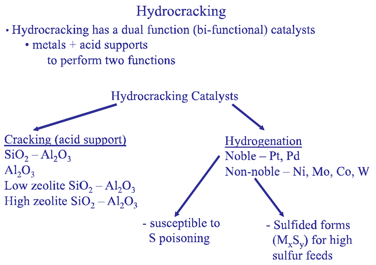
The two different reaction systems in hydrocracking, hydrogenation and cracking, are supported by bifunctional catalyst formulations, as illustrated in Figure 7.11. Hydrogenation reactions are promoted by the metal component of the catalysts (e.g., Ni, Co, Mo), and the cracking takes place on catalyst support consisting of silica/alumina. Highly active noble metals (e.g., Pt, and Pd) can be used for hydrogenation of hydrocarbons with extremely low sulfur contents as the noble metals are susceptible to sulfur poisoning.
Hydrocracking
-Hydrocracking has a dual function (bifunctional) catalyst
-Metals + acid supports to perform two functions
-Hydrocracking Catalysts
-Cracking (acid Support
-SiO2 – Al2O3
-Al2O3
-Low zeolite SiO2 – Al2O3
-High zeolite SiO2 – Al2O3
-Hydrogenation
-Noble – Pt, Pd
-Susceptible to S poisoning
-Non-noble – Ni, Mo, Co, W
-Sulfided forms (MxSy) for high sulfur feeds
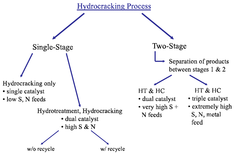
Hydrocracking processes most commonly include two reaction stages: Hydrotreating to remove heteroatom (S, N, O) species and Hydrocracking to increase the H/C ratio of the hydrocarbons in the feeds by hydrogenation and to decrease their molecular weight by cracking. In most cases, the hydrotreating reactor (HT) packed with cobalt-molybdenum catalysts precedes the hydrocracking (HC) reactor typically packed with nickel-tungsten catalysts (for hydrogenation) supported on alumina/silica (for cracking). Figure 7.12 shows different configurations of hydrocracking processes, depending on the heteroatom content of the feeds. For feeds with very low heteroatom contents, hydrocracking without hydrotreating may be applied, but this is very rare. Other process configurations include single stage with dual catalysts, two-stage dual and triple catalysts, as shown in Figure 7.11. The hydrocracking reactions are performed at 300–400°C and 8–15 MPa of hydrogen pressure.
Uses of Hydrocracking
Uses of Hydrocracking
In a refinery, hydrocracking complements catalytic cracking by taking on the more aromatic feedstocks that resist cracking, including the byproducts of FCC, such as light cycle oil (LCO). Hydrocracking can also be used to upgrade residual fractions using different reactor configurations and catalysts depending on the complexity of the upgrading tasks, as shown in Figure 7.12. As shown in Figure 7.13, for hydrocracking a relatively light feedstock (e.g., atmospheric residue), a fixed-bed configuration and relatively large-size catalyst particles can be used. In extreme cases with very heavy vacuum residue, an expanded bed configuration is used, in which very fine catalyst particles are entrained in the feed at high hydrogen pressures (high hydrogen/oil ratio). These extreme reaction conditions are necessary to prevent extensive coking on catalysts that could shut down the process. For intermediate cases, an ebullated (fluidized) bed configuration can be used, as shown in Figure 7.13.
In the United States, hydrocracking of LCO (from FCC) provides a large proportion of the diesel fuel production because straight-run LGO is a preferred stock for FCC to produce gasoline as the principal product. The major licensors of hydrocracking processes include Chevron, UOP, ExxonMobil Research and Engineering, BP, Shell, and BASF-IFP.
Hydrocracking Process
-Single Stage
-Hydrocracking only
-single catalyst
-low S, N feeds
-Hydrotreatment, Hydrocracking
-dual catalyst
-high S&N
-can be done with or without recycling
-Two-Stage (separation of the products between stages 1 & 2)
-HT & HC
-dual catalyst
-very high S + N feeds
-HT & HC
-triple catalyst
-extremely high S, N, metal feed
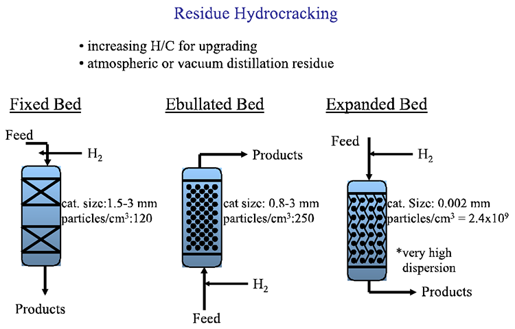
Residue Hydrocracking
-increasing H/C for upgrading
-atmospheric or vacuum distillation reside
| Bed Type | Cat. Size | Particles/cm3 |
|---|---|---|
| Fixed | 1.5 - 3mm | 120 |
| Ebullated | 0.8 - 3mm | 250 |
| Expanded | 0.002mm | 2.4x10⁹ |
Hydrocracking vs. Catalytic Cracking
| Catalytic Cracking - FCC | Hydrocracking |
|---|---|
|
-carbon rejection -endothermic -acid catalyst -more gas -more coke |
-hydrogen addition -exothermic -metal catalyst on acid support -less gas -less coke -costly process ($$$) |
- Hydrocracking involves C-C bond cleavage to produce lighter HC's
- More liquid yield with HYDRCRC
- More hydrogenated products
- Cracking is less severe
- Secondary cracking reactions are minimized by stabilization of active species by hydrogen
- Hydrocracking is more flexible w.r.t. the feedstock
- Refractory feedstocks (i.e. aromatics) can be processed
- C-C bond breaking after saturation with hydrogen
Above, we compare catalytic cracking (FCC - a carbon rejection process) with hydrocracking (HYDRCRC) with respect to the major attributes of both projects. Clearly, in a flexible refinery with a wide range of crude oil feedstocks, both processes are needed for the optimum conversion of the crude oil into desirable refinery products.
Self-Check Questions
Self-Check Questions
Please take a few minutes to answer the questions below. When you are satisfied with your responses, click Check My Answers to see how well you understood this lesson. These questions will help you study for the next quiz.
Assignments
Assignment Reminders
Exercise 6: Solve a problem on the material balance for the regenerator in Fluid Catalytic Cracking Process.
Quiz 3. Will cover material in Lessons 6 and 7. Check the Syllabus, or Course Calendar for Quiz 3 schedule.
Exercise 6
Exercise 6 Instructions
Solve a problem on the material balance for the regenerator in Fluid Catalytic Cracking Process.
Material Balance for FCC Regenerator
Problem
Burning the coke deposited on the catalyst particles generates all the heat necessary for catalytic cracking. Therefore, the coke burning rate is a critical parameter to control the rate of cracking. The composition of dry flue gas (excluding water) from the regenerator of an FCC unit is given in vol% as follows:
| Gas | Volume % |
|---|---|
| N2 | 81.6 |
| CO2 | 15.7 |
| CO | 1.5 |
| O2 | 1.2 |
The dry air (excluding moisture in the air) flow rate to the regenerator is given as 593 SCMM (standard cubic meters per minute). Considering that a significant portion of coke is carbon, calculate the carbon burning rate in the regenerator in kg/min. Remember: 1 kgmole at STP = 22.4 m3)
Hints:
In previous offering of this course, I have noted a serious weakness in the students' understanding of how to carry out simple mass balances. Here a few reminders and hints to solve this problem:
- Gas compositions are always reported as volume % (equivalent to mole %), not in mass, or weight%.
- Inert compounds (such as N2)go through reactors unchanged. These are referred to as "tie compounds." In this problem, knowing the air flow rate, you can calculate # moles of air, and thus # moles of nitrogen entering the reactor to calculate # moles of the flue gas, knowing the N2 % in the flue gas.
- After calculating the # moles of flue gas components and knowing their molecular weight, you can calculate the corresponding mass (weight) of the elements making up the flue gas molecules, e.g carbon in kg/min.
- If you still have questions on how you can use basic mass balances to solve this problem, please post them in the discussion forum.
Instructions for Submitting Response:
Once you have a solution to the exercises, you will submit your answers as a PDF by uploading your file to be graded. The MS Word, or Excel files should be saved as a PDF before submitting the exercise. Please Note: Scans of handwritten pages are not acceptable.
Please follow the instructions below.
- Find the Exercise 6 assignment in the Lesson 7 Module by either clicking Next until you find it, or by clicking Assignments and scrolling down until you find it.
- Make sure that your name is in the document title before uploading it to the correct assignment (i.e. Lesson7_Exercise6_Tom Smith).
Summary and Final Tasks
Summary
Catalytic processes constitute the core of the petroleum refineries to accomplish a number of conversion and finishing tasks. Catalytic cracking has been developed to produce high yields of gasoline with high octane # from high-boiling stocks using catalysts. Compared to thermal cracking, catalytic cracking takes place at lower temperatures and pressures and proceeds through carbocationic active species produced on acidic sites on catalyst surfaces. Fluid Catalytic Cracking (FCC) has become a universal refining process because of its high efficiency and feed flexibility. This process involves breaking up long chains of n-alkanes into shorter chains of branched alkanes (isoalkanes), cycloalkanes (naphthenes), and aromatics in high yields. Although the main product from FCC is high-octane number gasoline, it also produces LPG, cycle oils, and olefin-rich light hydrocarbons (C3, C4). The olefins are used as petrochemical feedstocks, or as reactants in alkylation and polymerization reactions, to produce higher molecular weight branched alkanes and olefins to contribute to the high-octane gasoline pool. Hydrocracking processes have been introduced for upgrading heavier crude oil fractions such as heavy vacuum gas oil (HVGO) and vacuum distillation residue VDR. The heaviest fractions of crude oil, HVGO and VDR, may not be easily processed by FCC because of potential problems with excessive coking on the catalysts. For upgrading these high-boiling and aromatic-rich feedstocks, hydrogen is introduced in the hydrocracking process, along with bifunctional catalysts systems, to keep coking under control while upgrading the heavy fractions to light and middle distillates.
Learning Outcomes
You should now be able to:
- distinguish the chemistry of catalytic cracking from the chemistry of thermal cracking and illustrate the formation of carbocations and IUPAC terminology for classification of carbocations;
- categorize the formation of different carbocations on active sites of cracking catalysts and assess the classification of acid sites (Lewis vs Bronsted) on catalyst surfaces;
- compare with examples how the product yields and composition obtained from catalytic processes differ from those from thermal cracking processes;
- analyze the thermodynamics of carbocation formation and evaluate how ionic chain reactions produce hydrocarbons with high octane numbers;
- appraise the historical evolution of catalytic cracking processes and formulate the driving forces that have shaped this evolution in reactor design and catalyst development;
- locate the hydrocracking process and hydroprocessing in the refinery flow diagram, illustrate hydrocracking processes, and evaluate different process objectives.
Reminder - Complete all of the Lesson 7 tasks!
You have reached the end of Lesson 7! Double-check the to-do list below to make sure you have completed all of the activities listed there before you begin Lesson 8. Please refer to the Course Syllabus for specific time frames and due dates. Specific directions for the assignments below can be found within this lesson.
| Readings | J. H. Gary, G. E. Handwerk, Mark J. Kaiser, Chapters 7 (Catalytic Hydrocracking) and Chapter 8 (Hydroprocessing and Resid Processing |
|---|---|
| Assignments | Exercise 6: The dry air flow rate to the regenerator is given as 593 SCMM (standard cubic meters per minute). Considering that a significant portion of coke is carbon, calculate the carbon burning rate in the regenerator in kg/min. Remember: (1 kgmole at STP = 22.4 m3). Quiz 3. Will cover material in Lessons 6 and 7. Check the Syllabus, or Course Calendar for Quiz 3 schedule. |
Questions?
If you have any questions, please post them to our Help Discussion (not email), located in Canvas. I will check that discussion forum daily to respond. While you are there, feel free to post your own responses if you, too, are able to help out a classmate.