Lesson 10: Supporting Processes
Lesson 10 Overview
Overview
Video: FSC 432 Lesson 10 (6:33)
PRESENTER: Now, this is the last kind or the fourth kind of processes found in a petroleum refinery, the supporting process. Interestingly enough, you will see that we also make a product here, another product that the refinery could sell, a byproduct, if you will, to make revenue for the refinery. So supporting processes make sure that the refinery could actually run.
It's not a huge chemical conversion process, if you will, that have to do with making the desirable hydrocarbons. But the principal supporting process is acid gas recovery and sulfur recovery or acid gas removal and sulfur recovery. What is acid gas? Well, H2S is the principal acid gas that is produced in a refinery from the hydro treatment processes.
Remember, we remove sulfur from the fuels, from the fractions of crude oil as hydrogen sulfide. Hydrogen sulfide is an acidic gas. So it needs to be removed from the rest of the gases, typically, methane, ethane, that come with hydrogen sulfide to the recovery or the removal acid gas removal process.
And we use a basic solvent to capture the acid gas, particularly hydrogen sulfide. So it's essentially an acid based interaction. We can use ethanolamine as a base in a solvent extraction process and in a liquid extraction process to remove high H2S, hydrogen sulfide, from methane, ethane, other hydrocarbons that are not acidic. You will see that we also have some carbon dioxide that is found along with H2S. That's also an acidic gas that tends to be separated with hydrogen sulfide party by solvent extraction and this basic solvent.
So once H2S is captured or removed using the solvent extraction process, now we need to convert that into a sellable product. I know people always think that here is a point we could recover hydrogen for reuse. Hydrogen, being such a valuable material. But unfortunately, that is not possible.
We need to burn hydrogen into water waste pretty much, hydrogen, so that we can recover sulfur as an elemental sulfur, in a solid or liquid form, that is sold to a chemical industry, chemical manufacturing industry. You know that the basic material, the primary chemical that is made from sulfur for the chemical industry is sulfuric acid manufacturing. So you use sulfur, elemental sulfur, produced in refineries in large quantities to make sulfuric acid, which is a very important raw material, a reactant in many chemical processes.
So instead of mining for sulfur, as was done in the early days, now sulfur, a large fraction of sulfur, almost 2/3 of sulfur used in sulfuric acid manufacturing, comes from petroleum refineries as a byproduct. Why is that? Because the crude oil that is refined in then these refineries becoming more sour or higher sulfur content, that should be removed because we would like cleaner fuels by environmental regulations.
So dirtier crude oil means higher sulfur crude oil coming in. And we need cleaner fuels because increasingly strict environmental regulations on the sulfur content, particularly on diesel fuel. And that gives us large quantities of sulfur recovered in the supporting processes. There are two back to back processes, as you will see, Claus and SCOT, to remove elemental sulfur and sell it as a byproduct from the refinery.
The last process we will talk about, and as a supporting process, is of course wastewater treatment. Water and steam are used in huge quantities. There is no process in petroleum refining that steam or water is not used. And of course, a refinery generates a lot of wastewater.
There are different extents of contamination. There is actually steam or water that comes into direct contact with the hydrocarbons or crude oil. Those are the most heavily polluted water. They should be treated separately.
One very important point to make, in order to have the best water treatment process, the key is segregation of the waste streams. You don't want to mix the waste water coming from, say, distillation with the stormwater. That is also contaminated because it runs through the surfaces of the refinery that may be contaminated with oil or other species. So we need to keep these streams segregated in the wastewater treatment process.
And we should also make some wise decisions about water use. For example, for desalting, you don't really need to use fresh water. You can use wastewater that is contaminated with hydrocarbons, but doesn't contain salt to remove salt from crude oil, the very first process before the distillation.
Overview
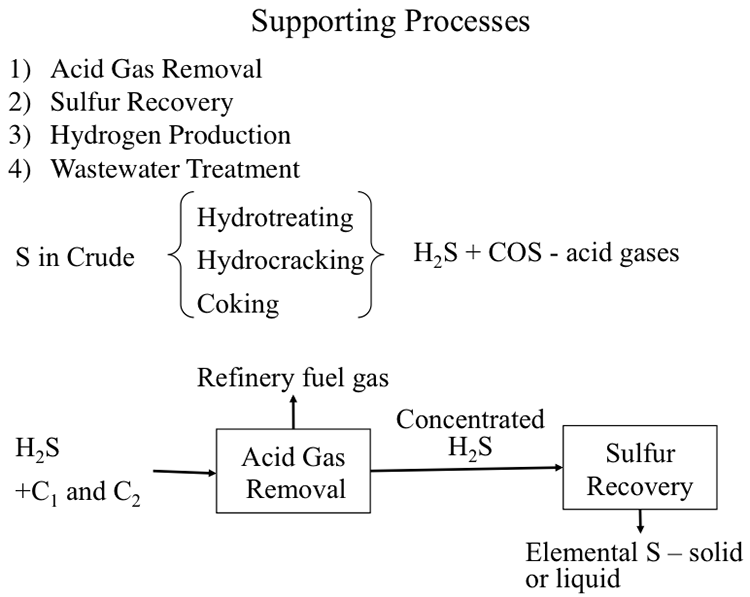
The fourth type of refining processes constitutes the supporting processes. Figure 10.1 lists the supporting role of these processes as:
- acid gas removal to separate and concentrate H2S and other acid gases produced in hydrotreatment and conversion operations;
- sulfur recovery from H2S captured in acid gas removal unit;
- hydrogen production for hydrocracking and hydrotreatment processes; and
- wastewater treatment.
Although these processes and units are not involved directly in hydrocarbon fuels production, their roles are essential for the operation of a refinery.
Learning Outcomes
By the end of this lesson, you should be able to:
- outline and assess the processes for acid gas removal and elemental sulfur recovery from H2S;
- discuss and illustrate sources of hydrogen and hydrogen production processes;
- assess primary water toxicants and waste water characterization parameters, and outline waste water treatment processes.
What is due for Lesson 10?
This lesson will take us one week to complete. Please refer to the Course Syllabus for specific time frames and due dates. Specific directions for the assignment below can be found in this lesson.
| Reading: | J. H. Gary and G. E. Handwerk, Chapter 13 (Supporting Processes) |
|---|---|
| Assignments: | Exercise 9 |
Questions?
If you have any questions, please post them to our Help Discussion (not email), located in Canvas. I will check that discussion forum daily to respond. While you are there, feel free to post your own responses if you, too, are able to help out a classmate.
Gas Processing Unit
Gas Processing Unit
The gas streams produced in refinery units such as catalytic crackers, cokers, hydrocrackers, and reformers are sent to the Gas Processing Unit [1] in order to:
- recover C3-C6 hydrocarbons for LPG production (C3 and C4) and feedstocks (C5 and C6) for isomerization (light naphtha) and reformer (heavy naphtha) units;
- separate H2S in a sour gas stream that also contains C1 and C2 gases.
In some refineries, Gas Processing Units also function as Light End Units.
[1] Petroleum Refining, by J. H. Gary, G. E. Handwerk, M. J. Kaiser, 5th Edition, CRC Press NY, 2007, Chapter 13, Supporting Processes, pp. 278-280.
Acid Gas Removal
Acid Gas Removal
Sour gas separated in the Gas Processing unit is sent to the Amine Unit for acid gas removal using chemical solvents such as monoethanolamine (MEA), or diethanolamine (DEA), as shown in Figure 10.2.
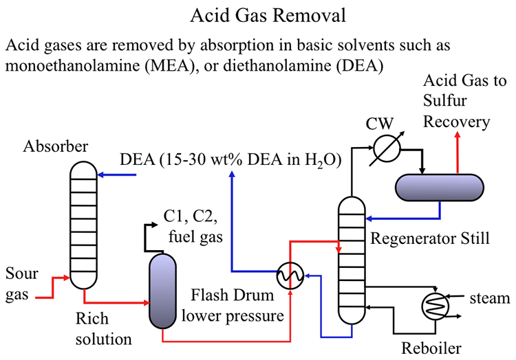
As shown in Figure 10.2, the sour gas is pumped from the bottom of an absorption column to get in contact with the basic solution (typically 15-30wt% diethanolamine) to capture H2S (and other acidic gases such as CO2) in the solution. The rich solution containing the acid gases is sent to a flash drum to recover the C1 and C2 hydrocarbons from the rich solution to be used as fuel gas in the refinery to generate process heat, or steam in fired furnaces. The rich solvent is then sent to a regenerator still to remove the acid gases that are sent to the sulfur recovery unit. The remaining solvent is cooled in a heat exchanger and recycled to the absorption unit to close the loop [2].
[2] Petroleum Refining, by J. H. Gary, G. E. Handwerk, M. J. Kaiser, 5th Edition, CRC Press NY, 2007, Chapter 13, Supporting Processes, pp. 280-283.
Sulfur Recovery
Sulfur Recovery
As indicated in Figure 10.3, the objective of the sulfur recovery process is to convert H2S to elemental sulfur. Sulfur recovery takes place in a series of two steps: Claus Process and SCOT Process [3]. In the Modified Claus Process, partial combustion of H2S takes place to generate SO2 that is reacted with the remaining H2S to recover sulfur as elemental sulfur. The Modified Claus Process, once-through burner operation, works only with acid gases that contain more than 50% H2S by volume. In the process, hydrogen in H2S is converted to H2O. The second stage, the SCOT Process, functions as a tail gas clean-up operation to remove the sulfur compounds produced in the side reactions of the Claus Process, i.e., carbonyl sulfide (COS) and carbon disulfide (CS2).
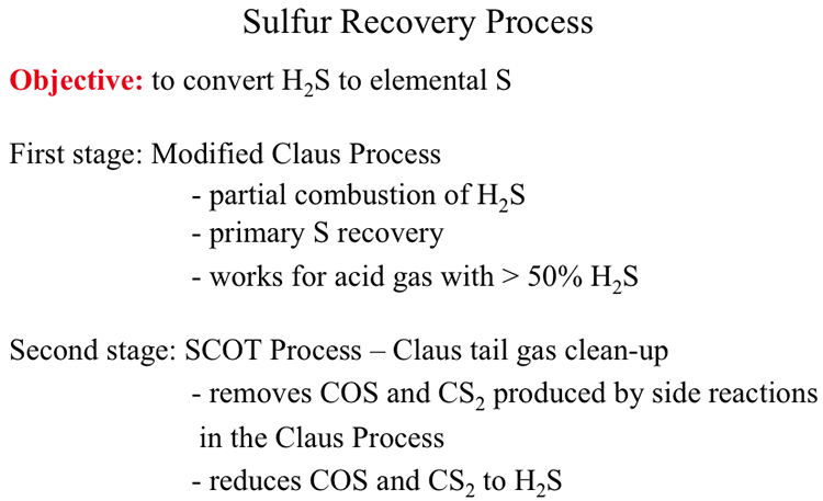
Sulfur Recovery Process
Objective: to convert H2S to elemental S
First stage: Modified Clause Process
-partial combustion of H2S
-primary S recovery
-works for acid gas with >50% H2S
Second Stage: SCOT Process – Claus tail gas clean-up
-removes COS and CS2 produced by side reactions in the Clause Process
-reduces COS and CS2 to H2S
[3] Petroleum Refining, by J. H. Gary, G. E. Handwerk, M. J. Kaiser, 5th Edition, CRC Press NY, 2007, Chapter 13, Supporting Processes, pp. 283-290.
Modified Claus Process
Modified Claus Process
Figure 10.4 shows the configuration of the multi-step Modified Claus Process that includes two kinds of reactors: a burner reactor and a converter reactor. In the burner reactor, H2S is burned with compressed air to SO2 and H2O. Two critically important variables of the burner reactor are the oxygen to H2S ratio and the reactor temperature. The O2/H2S ratio needs to be one-third of the stoichiometric ratio for complete combustion of H2S. The significance of the O2/H2S will be discussed further in the next section. The temperature in the burner reactor must be maintained typically at 1850°F to make sure that any ammonia present in the feed gas is completely destroyed to protect the catalysts in the converter reactor. The effluent gas from the burner reactor is cooled to 450°F (above the dew point of S) in the waste heat boiler as it enters the converter reactor for catalytic conversion of H2S and SO2 to elemental sulfur and water. The converter effluent is introduced into a condenser unit to obtain elemental sulfur as a liquid product. Small quantities of S produced in the burner reactor may also be recovered after the waste heat boiler. Typically, three sets of converter-condenser units in series are needed to achieve 95% recovery of S in the Modified Claus Process.

Figure 10.5 shows the principal reactions in the Modified Claus Process in the burner and converter-reactor sections. In the burner, H2S is partially oxidized to produce H2O and SO2. In the reactor converter, the burner product SO2 reacts with the remaining H2S to produce elemental sulfur (the intended product in the sulfur recovery process) along with the side product water. Ideally, the final products should consist only of elemental sulfur and water with no H2S or SO2 present. The only way to achieve the intended product mix is to control the O2/H2S ratio in the burner. As can be seen, the stoichiometric ratio of O2/H2S for complete conversion of H2S to SO2 is 3/2 which would effectively convert all H2S to SO2. In order to reserve part of the feed H2S to react with the burner product so that no H2S or SO2 remains in the final product from the converter, the O2/H2S ratio should be controlled at 1/3 of the stoichiometric ratio, that is (1/3)(3/2)=1/2. As a self-check exercise, explain with chemical equations why the desired oxygen/hydrogen sulfide ratio in the feed to the Burner in the Claus Process should be 1/3 of the stoichiometric oxygen/hydrogen sulfide ratio (for complete combustion of hydrogen sulfide). The answer to this exercise is given at the end of the lesson.
As seen in Figure 10.5, the side reactions in the burner produce COS and CS2 which cannot be converted in the catalytic reactions that take place in the converter reactor. Therefore, a tail gas clean-up process, or SCOT Process, is needed to reduce the concentration of these side products to less than 20 ppm by volume in the outlet.
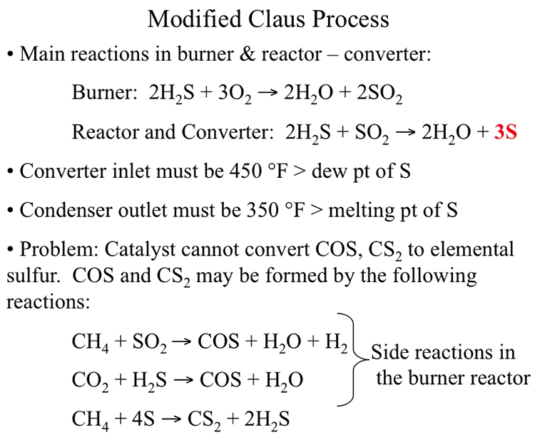
Modified Claus Process
Main reactions in burner & reactor – converter:
Burner: 2H2S + 3O2 → 2H20 + 2SO2
Reactor and Converter 2H2S + SO2 → 2H2O + 3S
Converter inlet must be 450ºF > dew point of S
Condenser outlet must be 350ºF > melting point of S
Problem: Catalyst cannot convert COS, CS2 to elemental sulfur. COS and CS2 may be formed by the following reactions
CH4 + SO2 → COS + H20 + H2 (Side reaction in the burner reactor)
CO2 + H2S → COS + H20 (Side reaction in the burner reactor)
CH4 + 4S → CS2 + 2H2S
SCOT Process
SCOT Process
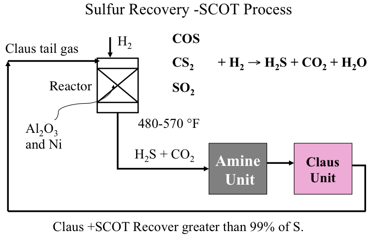
Figure 10.6 illustrates how the SCOT Process is integrated with the Claus Unit to convert COS, CS2 and any remaining SO2 by reacting with H2 in the catalytic reactor back to H2S to be recycled to the Claus Unit to close the loop. The hydrogenating catalysts used in SCOT contain nickel or tungsten on alumina support, and the reaction takes place at 480-570°. By coupling Claus and SCOT processes, more than 99% of sulfur entering the Claus unit can be recovered as elemental sulfur to be sold as a refinery product.
Hydrogen Production
Hydrogen Production
Although refineries produce a significant quantity of hydrogen needed for hydrotreating and hydroconversion processes, in most cases, additional hydrogen is needed particularly for refining the sour crudes. Therefore, a Hydrogen Plant is needed on site to provide the additional hydrogen demand. As seen in Figure 10.7, steam reforming of natural gas is most commonly used in the U.S. to produce hydrogen, whereas partial oxidation of heavy hydrocarbons is preferred in Europe [4].
For the partial oxidation process, a heavy hydrocarbon fraction, typically fuel oil, is reacted at high pressures (1300-1800 psig) with pure oxygen supplied in strictly controlled quantities for partial oxidation of hydrocarbons to carbon monoxide and hydrogen, as shown in Figure 10.7. Carbon monoxide produced in the reaction is converted to hydrogen by catalytic shift reaction with steam. In the purification step, CO2 produced in the shift reaction is removed by absorption in a basic solvent such as potassium carbonate.
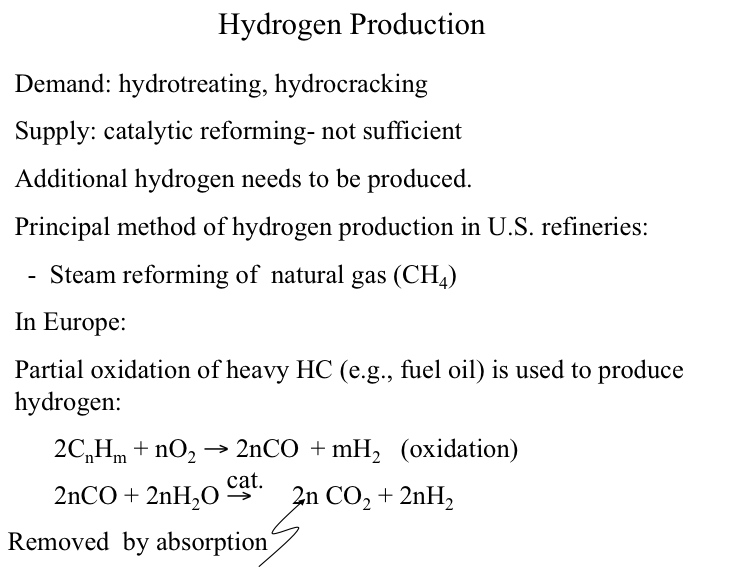
Image reads:
Hydrogen Production
Demand: hydrotreating, hydrocracking
Supply: Catalytic reforming – not sufficient
Additional hydrogen needs to be produced
The principle method of hydrogen production in US refineries:
-Steam reforming of natural gas (CH4)
The principle method of hydrogen production in European refineries:
-Partain oxidation of heavy HC (e.g., fuel oil) is used to produce hydrogen
2CnHm + nO2 → 2nCO + mH2 (oxidation)
2nCO + 2nH2O → 2nCO2 (removed by absorption) + 2nH2
Figure 10.8 illustrates the reactions in steam reforming of natural gas (CH4) to produce hydrogen in the U.S. refineries. In the reforming reaction, CH4 is converted to H2 and CO on a NiO/SiO2-Al2O3 catalyst at temperatures of 760-816°C. Reforming is followed by the water gas shift reaction at 343°C to shift CO to H2 and CO2 on a Cr2O3 and Fe2O3 catalyst in multiple catalyst beds with external cooling to control the temperature to achieve high conversion in the exothermic reaction. The product gas is purified by absorption of CO2 in an Amine Unit. In the final step of methanation, residual CO and CO2 is removed by hydrogenation on a Ni/Al2O3 catalyst at 370-427°C.
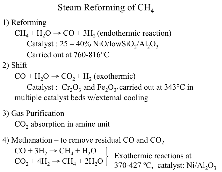
Image reads:
Steam Reforming of CH4
1) Reforming
CH4 + H2O → CO + 3H2 (endothermic)
Catalyst: 25-40% NiO/low SiO2/ Al2O3
Carried out at 760-816ºC
2) Shift
CO + H2O → CO2 + H2 (exothermic)
Catalyst: Cr2O3 and Fe2O3
Carried out at 343ºC in multiple catalyst beds w/ external cooling
3) Gas Purification
CO2 absorption in amine unit
4) Methanation - to remove residual CO and CO2
CO + 3H2 → CH2 + H2O (Exothermic)
CO2 + 4H2 → CH2 + 2H2O (Exothermic)
Carried out at 370-427ºC
Catalyst: Ni/Al2O3
[4] Petroleum Refining, by J. H. Gary, G. E. Handwerk, M. J. Kaiser, 5th Edition, CRC Press NY, 2007, Chapter 13, Supporting Processes, pp. 273-278.
Wastewater Treatment
Wastewater Treatment
Considering the vast amounts of water used in a refinery, wastewater treatment constitutes a very significant supporting process for safe operation. Figure 10.9 lists the different types of wastewater, pollutants involved in wastewater streams, and the major refinery units that generate significant amounts of wastewater. The four types of refinery wastewater include cooling water, process water and steam, storm water, and sanitary sewage water. Among these, the most heavily polluted wastewater stream that requires serious treatment is the process water and steam that come into direct contact with petroleum fractions. Storm water may be contaminated because of incidental exposure to pollutant sources on refinery surfaces and accidental spills. Cooling water and sanitary sewage water may not require much treatment before they are sent to public water treatment facilities. One rule of thumb is to avoid mixing different types of wastewater streams to reduce the load on the treatment units.
Pollutants found in the wastewater streams include hydrocarbons with particular concern for toxic aromatic compounds, such as benzene; heteroatom compounds, such as mercaptans, amines, phenols, and cyanides; dissolved gases such as H2S and NH3, and acids, such as H2SO4 and HF; and suspended and dissolved solids. The refinery units that generate the most significant amount of wastewater are desalting, distillation, thermal and catalytic cracking, coking, as well as heat exchangers and storage tanks [5].
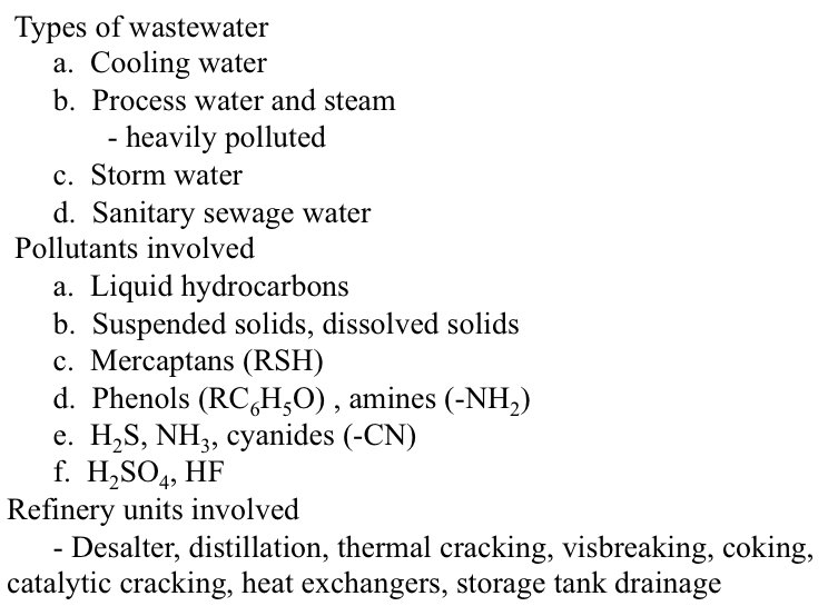
Types of wastewater
a. Cooling water
b. Process water and steam
-heavily polluted
c. Stormwater
d. Sanitary sewage water
Pollutants involved
a. Liquid hydrocarbons
b. Suspended solids, dissolved solids
c. Mercaptans (RSH)
d. Phenols (RC6H5O), amines (-NH2)
e. H2S, NH3, cyanides (-CN)
f. H2SO4, HF
Refinery units involved
Desalter, distillation, thermal cracking, visbreaking, coking, catalytic cracking, heat exchangers, storage tank drainage
[5] Petroleum Refining, by J. H. Gary, G. E. Handwerk, M. J. Kaiser, 5th Edition, CRC Press NY, 2007, Chapter 13, Supporting Processes, pp. 290-293.
Wastewater characterization
Wastewater characterization
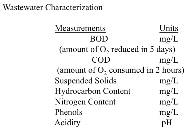
Standard measurements used for wastewater characterization are listed in Figure 10.10. Biochemical Oxygen Demand (BOD) measures the amount of oxygen consumed by microorganisms in decomposing organic matter, whereas Chemical Oxygen Demand (COD) measures the total oxygen consumption by organic and inorganic chemicals present in water. Both measurements relate to the level of contamination in wastewater, and they are used to gauge the effectiveness of the wastewater treatment processes. Other water quality parameters include the amount of suspended solids, hydrocarbon content, nitrogen content, phenols content, and acidity.
Primary and secondary treatment processes
Primary and secondary treatment processes
Figures 10.11 and 10.12 illustrate the primary (physical) and secondary (biological) treatment processes, respectively. The primary treatment of sour water contaminated with oils and solid particles involve the stripping of dissolved H2S using steam, float/sink density separation for skimming the floating oil, and the settling tanks to separate heavier oil and solids, usually in multiple stages, before the treated water can be directed to public treatment facilities. The secondary treatment uses micro-organisms to further remove organic contaminants.
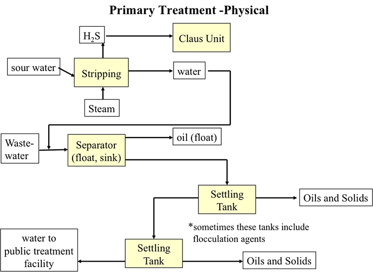
Simplified primary treatment diagram. Sour water and steam undergo stripping. H2S is removed and sent to a Claus Unit. Everything else is sent, with wastewater to the separator (float, sink). Oil floats and is removed, the rest goes to two successive settling tanks (which sometimes include flocculation agents) where oils and solids are removed. Finally, the remaining water is sent to a public treatment facility.
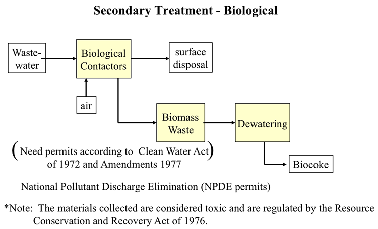
Simplified secondary treatment diagram. National pollutant discharge elimination (NPDS) permits are needed according to the clean water act of 1972 and amendments of 1977. The materials collected are considered toxic and are regulated by the resource conservation and recovery act of 1976.
Wastewater and air enter biological contactors. From there some products go to surface disposal and some of the products go to biomass waste, then dewatering and is finally turned into biocoke.
Environmental Regulation of Refineries
Environmental Regulation of Refineries
Air pollutant emissions from the refinery processes are also controlled. Figure 10.13 lists the major legislations and regulations that affect the environmental impact of refineries in the U.S. [6].
- Clean Water Act (CWA)
- Safe Drinking Water Act
- Clean Air Act of 1963
- Clean Air Act of 1970 (CAA) and regulations
- Clean Air Act Amendments of 1977 and 1990 (CAAA) and regulations thereunder
- Clear Skies Act of 2003
- Resource Conservation and Recovery Act (RCRA)
- Superfund: Comprehensive Environmental Response, Compensation, and Liability Act (CERCLA)
- Emergency Planning and Community Right-to-Know (EPCRA)
- Occupational Safety and Health Act (OSHA)
- Toxic Substances Control Act (TSCA)
- Oil Pollution Act
- Spill Prevention Control and Countermeasure Plans
[6] C. S. Khor and A. Elkamel, “Environmental Issues Related to the Petroleum Refining Industry” In Petroleum Refining and Natural Gas Processing, Editors: M. R. Riazi, S. Eser, J. L. Peña, ASTM International, West Conshohocken, PA, 2013, pp. 701-716.
Self-Check Questions
Self-Check Questions
Please take a few minutes to complete the exercise and then answer the questions below.
Assignments
Assignment Reminder
This week Exercise 9 is due.
Summary and Final Tasks
Summary
Supporting processes are essential to the operation of a refinery. These processes have become more important as the crude oil base has become more sour. The demand for hydrogen has increased to support the required finishing processes for heteroatom removal and recovery of sulfur and metals. Refineries have become major producers of elemental sulfur for the chemical industry.
Learning Outcomes
You should now be able to:
- outline and assess the processes for acid gas removal and elemental sulfur recovery from H2S;
- discuss and illustrate sources of hydrogen and hydrogen production processes;
- assess primary water toxicants and waste water characterization parameters, and outline waste water treatment processes.
Reminder - Complete all of the Lesson 10 tasks.
You have reached the end of Lesson 10! Double-check the to-do list below to make sure you have completed all of the activities listed there before you begin Lesson 11.
What is due for Lesson 10?
Please refer to the Course Syllabus for specific time frames and due dates. Specific directions for the assignments below can be found within this lesson.
| Reading: | J. H. Gary and G. E. Handwerk, Chapter 13 (Supporting Processes) |
|---|---|
| Assignments: | Exercise 9 |
Questions?
If you have any questions, please post them to our Help Discussion Forum (not email), located in Canvas. I will check that discussion forum daily to respond. While you are there, feel free to post your own responses if you, too, are able to help out a classmate.