Lesson 11: Past and Future of Petroleum Refining
Lesson 11 Overview
Overview
Video: FSC 432 Lesson 11 (5:18)
PRESENTER: Now we have talked about on many occasions the evolution of a refinery based on, of course, the demands for the products. All the way from a one pot distillation refinery. Or we can call it a separation refinery. Just to make kerosene for the lamps, for lighting.
Now it's widely considered and claimed that very process saved the whales from extinction. Because instead of now using whale oil in lamps, one could use kerosene without much smoke. And the light to actually let people extend daylight in essence.
Of course, with the electric light, kerosene was not demanded. But as you know, as we've talked about before, the demand for another fuel, or gasoline, was increasing. So from separation, or distillation refinery, we went to the thermal refinery to make more gasoline for the increasing number of automobiles. And, of course, the lubricating oil that is needed in these engines.
So the thermal refinery performed quite well, up until the 2nd World War, to use just heat to make the chemical changes that are needed to change the composition of the crude oil to fit with the product demand in essence. With the 2nd World War raging, with the demand for high performance fuels, the catalytic processes were introduced.
So we are in the catalytic refinery, taking over from the thermal refinery. And the catalytic refinery continued, of course, after the 2nd World War. An interesting historical note.
The oil companies that were competing before the 2nd World War, in the United States, and in Western Europe, got together to develop these catalytic, many of these catalytic processes that are still used today. In an effort, obviously, to develop more powerful fuels for the war effort.
So that is a very interesting era in the history of petroleum refining, where competition turns into collaboration. To make, of course, more powerful fuels for the more powerful war machine. Until the end of the century, obviously, this trend continued.
And the next stage is referred, in some text, as the end of the century refinery. Where the focus now is really on the very heavy end. Because as we are using crude oil in the marketplace, the crude oil available for becoming or for refining becomes heavier.
So when you do the distillation, there's a huge amount of active distillation residue that is separated. So the end of the century refinery focuses on treating these heavy ends, essentially hydro processing. Using different reactor configurations. Using essentially the chemistry, chemical modeling, to determine the reaction chemistry.
Kinetics for more optimum conversion of these very heavy ends. The most challenging parts of the crude oil to be converted into the light distillates.
So on one hand, we have an increasing demand for lighter fuels like gasoline, diesel, jet fuel. And on the other hand, we do have a crude oil base that is getting increasingly heavier, and dirtier. So the end of the century refinery focused on treating and hydro treating these heavy ends to make the lighter and cleaner products.
As we have mentioned at the beginning of this course, there's a new trend. That is the hydro fracking to make, essentially to produce shale gas. But there is a liquid byproduct. And it won't be too long before hydro fracking is used to produce oil also.
So in the 21st century we may see yet another significant change in the refinery scheme to incorporate shale oil that is produced by hydro fracking into the refinery. To be refined into the mix of the fuels and materials that are needed in the marketplace.
Overview
In the roughly 150-year history of petroleum refining, remarkable changes have taken place in refining processes and refinery configurations. These changes were driven by transitions and developments in combustion engines, the wars (World War I and, most notably, World War II), variations in the crude oil slate available for refining, and the environmental regulations. This historical evolution has taken place with the introduction of new processes more or less in the order of the four refinery processes that we have discussed: separation, conversion, finishing, and support. The new petroleum refining processes were developed and incorporated into the refinery to control the yield and properties of the desired fuels and refineries. Through the stages of the refinery evolution, it is interesting to note that the demand for even the same petroleum product has changed not only in the desired composition, as it is linked to properties, but also in its application to a particular commercial sector. In this regard, kerosene provides a good example of this change from being primarily a source of light in lamps (as a replacement for whale oil which allegedly saved the sperm whales from extinction) in the 1850s to becoming an established base fuel for jet aircraft since the end of World War II. Kerosene has also been used as a fuel for domestic heating and cooking in many parts of the world, long after the introduction of electric lamps.
This lesson will provide an overview of the historical evolution of the petroleum refinery and discuss some current developments in crude oil supply and in related energy technologies to catch a glimpse of what the near future could bring to the refinery practice. The overview and discussions will often reflect on specific aspects of different refinery processes that have been introduced in previous lessons.
Learning Outcomes
By the end of this lesson, you should be able to:
- review, illustrate, appraise, and critique discrete stages in the history of petroleum refining;
- evaluate driving forces that could impact the future of petroleum refineries and propose scenarios for responding to the driving forces.
What is due for Lesson 11?
This lesson will take us one week to complete. Please refer to the Course Syllabus for specific time frames and due dates. Specific directions for the assignment below can be found in this lesson.
| Readings: | F. Self, E. Ekholm, and K. Bowers, Refining Overview - Petroleum, Processes and Products, AIChE CD-ROM, 2000. |
|---|---|
| Assignment: |
Exercise 10: Refinery Flow Diagrams Quiz 4. Will cover material in Lessons 10-11. Check the Syllabus or Course Calendar for Quiz 4 schedule. |
Questions?
If you have any questions, please post them to our Help Discussion (not email), located in Canvas. I will check that discussion forum daily to respond. While you are there, feel free to post your own responses if you, too, are able to help out a classmate.
Refinery Evolution
Refinery Evolution
The configuration and complexity of a petroleum refinery has evolved from one-pot batch distillation to produce kerosene as the major product (1850s) to the complex refinery of the day [1] that produces a multitude of fuels and petrochemical feedstocks from a wide range of crude oils, as discussed in Lessons 1 and 2. Different stages of this evolution, in tune with the changing demand for petroleum products as well as the changing crude oil base over time, are presented in the following sections listed below and in your menu.
Batch Fractionation (1855-1880)
Batch Fractionation (1855-1880)
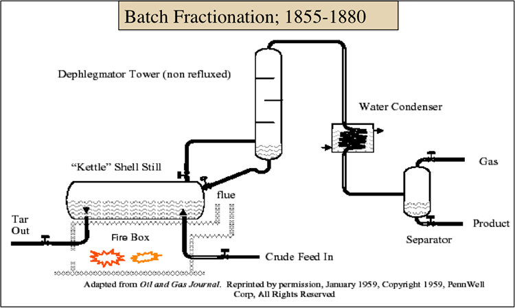
In the first refineries of the United States, Pennsylvania crude was easily distilled to produce kerosene for lamps (which burned cleanly without producing much smoke because of the paraffinic composition of Penn crude) and lubricating oil for steam engines. Lighter fractions obtained from distillation such as naphtha, propane, and butane were largely considered a nuisance and were flared for disposal because of their high vapor pressure and low flash points that would cause difficulties with storage. Figure 11.1 shows a typical batch distillation process in early refineries of the 1850s used primarily to produce kerosene, labeled as “product” from the separator in the diagram. For the distillation process, crude oil feed was filled into a kettle heated by burning gas, or other fuels in a fire box and the residual tar was removed after the distillation was over. The Dephlegmator Tower worked as a distillation column and as the crude boiled in the still, the vapor fraction from the dephlegmator was condensed and sent to the separator [2]. The separated kerosene fraction often went through a second distillation process to control the flash point for the safe use of fuel in lamps and reduce odor. The residue fraction was also distilled using vacuum to produce lubricating oil and grease for the steam engines and wax for making candles.
Charging the kettle with crude oil and emptying the residue left over from distillation took a lot of time and effort, making the batch distillation highly inefficient. In most cases, the recovered overhead fraction was fed back to the same still to drive off more hydrogen sulfide and lighter fractions to control the flammability (flash point) of kerosene. Driving off hydrogen sulfide and other light sulfur species also reduced the odor of kerosene and of the products obtained from burning kerosene in gas lamps. As the demand increased for kerosene, the refiners began to use two stills, one for the first fractionation of a kerosene cut and the second one to redistill the kerosene for purification. Using two stills in series marked the beginning of the continuous stills [2].
[2.] F. Self, E. Ekholm, and K. Bowers, Refining Overview - Petroleum, Processes and Products, AIChE, 2000, Chapter 4.
Continuous Fractionation (1880-1910)
Continuous Fractionation (1880-1910)
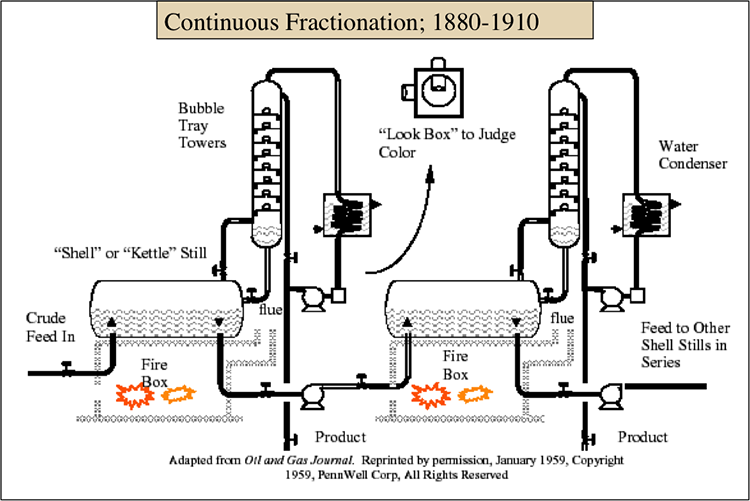
Continuous fraction with multiple stills replaced batch operations in the refineries, enabling increased throughputs and the production of multiple distillate fractions as products from a refinery [2]. As shown in Figure 11.2, a series of stills could operate continuously by taking an overhead fraction from the crude oil in the first still by flashing and moving the remaining liquid to a still drum while continuously introducing more fresh feed to the first still. The second still operates at a higher temperature to produce a higher boiling distillate. The reflux to the column with bubble trays was adjusted from the color of the overhead stream, utilizing a “look box,” shown in the diagram in Figure 11.2, to improve separation.
The demand for kerosene as a source of light declined with the invention of the electric light bulb in 1879. However, the first powered airplane flight in 1903 and mass production of an automobile (Model T) in 1908 ushered in a large demand for gasoline that cannot be met by simple distillation. Thermal cracking provided means to increase gasoline supply. This was the beginning of a new era in petroleum refining, incorporating a conversion process with separation processes.
The Thermal Refinery (1910-1940)
The Thermal Refinery (1910-1940)
Incorporating thermal cracking of gas oil into the refinery increased the yield of light and middle distillates, i.e., gasoline, kerosene, and diesel fuel, from crude oil. Although the electric light made the kerosene lamps obsolete, there was still continued demand for kerosene in rural regions because of slow electrification outside the urban areas. The evolution of the refinery in the three decades between 1910 and 1940 was driven largely by the development of thermal cracking processes, although finishing (or chemical treating) processes also started to become important in this era to stabilize and purify the products of thermal cracking.
Figure 11.3 shows a simple schematic diagram of the Burton-Clark batch thermal cracking process. The process employed tubular heating similar to those used in a steam boiler. The series of tubes in the firebox circulate the hot gas oil back to the drum by thermal convection for more uniform heating. The hot gases from the coal-fired furnace are directed up over the high end of the tubes and down over the low end of the slanted bundle. Feed is introduced in the low end of the tubes and tar is withdrawn from the bottom set of tubes. The products of thermal cracking are fractionated in the Bubble Tray Tower and in the high-pressure and low-pressure separators. In the high-pressure separator are the gaseous products hydrogen, methane, and ethane, and in the low-pressure separator are the gases ethane and propane and the liquid products gasoline and kerosene.
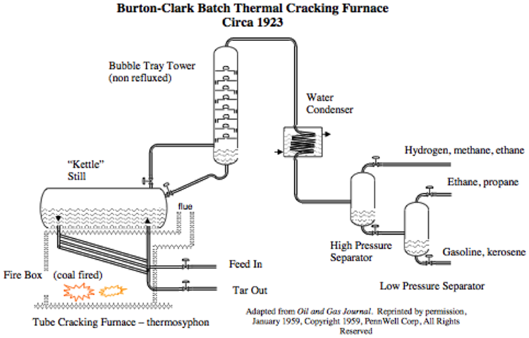
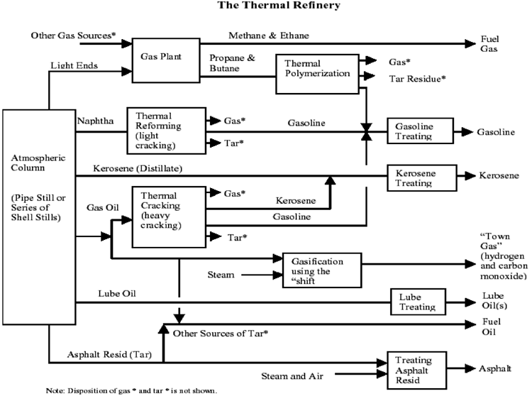
Figure 11.4 shows the configuration of different processes in the thermal refinery. As different from the thermal processes in a current refinery, the thermal refinery includes processes such as Thermal Polymerization, making gasoline from the light olefins propene and butene; Thermal Reforming, to make relatively high octane number gasoline from straight-run naphtha; and gasification of heavy gas oil with steam, to produce town gas (CO+H2) which predates the use of natural gas in cities for domestic heating and cooking.
Atmospheric Column (Pipe Still of Series of Shell Stills)
-Light ends & Other gas sources
Gas Plant
Methane and ethane (fuel gas)
Propane and Butane
Thermal Polymerization
Gas
Tar Residue
Gasoline (joins gasoline treating process)
-Naphtha
Thermal Reforming (light cracking)
Gas
Tar
Gasoline
Gasoline Treating
Gasoline
-Kerosene (Distillate)
Kerosene Treating
Kerosene
-Gas Oil
Thermal Cracking (heavy cracking)
Gas
Tar
Kerosene (Joins kerosene treating process)
Gasoline (joins gasoline treating process)
Gasification using the shift (uses Steam)
“town gas” (hydrogen and carbon monoxide)
-Lube Oil
Lube treating
Lube Oils
-Asphalt Resid (Tar)
Treating asphalt resid (uses steam and air)
Asphalt
-Other Sources of Tar
Fuel Oil
The essential driver of the Thermal Refinery was the shift in demand to gasoline from kerosene because of the introduction of the automobile, the airplane, and electricity. The demand for gasoline rapidly increased when the U.S. declared war on Germany in 1917 and became a party in World War I. Thermal refinery processes, thermal cracking, thermal reforming, and thermal polymerization enabled the expansion of gasoline supply [3]. With the introduction of tetraethyl lead (TEL) as an octane number boosting additive in 1923, a growing interest was directed to production of high-performance gasoline which would be defined later as a high-octane number-gasoline after the introduction of a test method to measure the octane number of gasoline as an anti-knock property in 1931. Because of the toxicity of lead, TEL concentration was limited to 3 milliliters per gallon of finished gasoline (approximately 800 ppm by volume). The addition of lead to motor gasoline continued until the 1970s in the United States when the mandate for adding catalytic converters to automobiles took effect in accordance with the Clean Air Act to reduce tailpipe emissions, and the unleaded gasoline was introduced. Lead is still added to aviation gasoline used in turboprop aircraft in quantities 0.3-0.56 g/L in a range of avgas grades, and efforts are underway to remove lead from the aviation gasoline as well in the near future.
Up through 1924, even with the rapid introduction of various thermal cracking processes, only 20% of the gasoline produced in the U.S. came from thermal processes. But after the introduction of TEL, the contribution of gasoline produced by thermal cracking has steadily increased to reach over 50% of the gasoline pool by the end of the age of the Thermal Refinery in 1940. For reasons discussed in Lessons 6 and 7, the Catalytic Refinery arrived in the scene of brutal competition of making high-performance gasoline and other petroleum fuels in the period leading to and during World War II.
[3.] F. Self, E. Ekholm, and K. Bowers, Refining Overview - Petroleum, Processes and Products, AIChE, 2000, Chapter 5.
The Catalytic Refinery (1940-1970)
The Catalytic Refinery (1940-1970)
As discussed in Lessons 6 and 7, the development of catalytic processes has changed the chemistry of petroleum refining from free radical to ionic reactions. World War II provided the stimulus to urgently develop catalytic technologies that were being investigated in the late thirties. The catalytic age of refining, which could be bracketed between1940 and 1970 also brought the advent of the petrochemical industry.
Figure 11.5 shows a configuration of the catalytic refinery which resembles, to a large extent, the current day refineries focused on making high yields of gasoline. The introduction of catalytic cracking, reforming, alkylation, polymerization has revolutionized the ways of making high octane number gasoline. Development of hydrotreatment processes was also an important asset of the catalytic refinery. Hydrotreatment was essential to protect the platinum catalyst used in reforming from sulfur and as a versatile finishing process to replace the chemical treatments used in the thermal refinery to finish fuels.
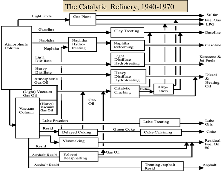
One should note in Figure 11.5 that the catalytic refinery also incorporated new thermal processes such as delayed coking and visbreaking, and separation processes, such as deasphalting. Principles of chemical engineering have found great applications in the development of the catalytic refinery with particular emphasis on designing different catalytic process configurations (remember Fixed-Bed, Moving-Bed, and Fluid-Bed Catalytic Cracking), catalyst development, thermal efficiency (e.g., FCC) and product yield and selectivity. The catalytic refinery produced large quantities of LPG (for reasons discussed in Lesson 7) and witnessed the increasing demand for kerosene, now as jet fuel. The time-line for the development of refining processes shown in Table 11.1 shows the intense activity of process development, particularly during World War II.
The age of catalytic refining may be considered to have ended in the 1970s, not because new chemistry was introduced, as it happened in the transition from thermal to catalytic refinery or the development of new process concepts. The oil crises of the 1970s highlighted the significance of refinery flexibility with respect to the diversity of crude oil slates. Further, the concerns for environmental pollution by the combustion of petroleum fuels have brought emphasis on more effective finishing processes. These factors lead to the development of the modern refinery focused on processing the heavy ends of petroleum and making cleaner fuels.
| Year | Process Name | Purpose | Byproducts, etc. |
|---|---|---|---|
| 1849 | Canadian geologist Abraham Gesner distills kerosine from crude oil | ||
| 1859 | An oil refinery is built in Baku (Azerbaijan) | ||
| 1860-1861 |
Oil refineries are built near Oil Creek, Pennsylvania; Petrolia, Ontario, Canada; and Union County, Arkansas |
||
| 1862 | Atmosphere distillation | Produce kerosine | Naphtha, tar, etc. |
| 1870 | Vacuum distillation | Lubricants (original) cracking feedstocks (1930s) |
Asphalt, residual coker feedstocks |
| 1913 | Thermal Cracking | Increase gasoline |
Residual, bunker fuel |
| 1916 | Sweetening | Reduce sulfur and odor | Sulfur |
| 1930 | Thermal reforming | Improve octane number | Residual |
| 1932 | Hydrogenation | Remove sulfur | Sulfur |
| 1932 | Coking | Produce gasoline base stocks |
Coke |
| 1933 | Solvent extraction | Improve lubricant viscosity index | Aromatics |
| 1935 | Solvent dewaxing | Improve pour point | Waxes |
| 1935 | Catalyst polymerization | Improve gasoline yield and octane number | Petrochemical feedstocks |
| 1937 | Catalytic cracking | Higher octane gasoline | Petrochemical feedstocks |
| 1939 | Visbreaking | Reduce viscosity | Increased distillate, tar |
| 1940 | Alkylation | Increase gasoline octane and yield | High-octane aviation gasoline |
| 1940 | Isomerization | Produce alkylation feedstock | Naphtha |
| 1942 | Fluid catalytic cracking | Increase gasoline yield and octane | Petrochemical feedstocks |
| 1950 | Deasphalting | Increase cracking feedstock | Asphalt |
| 1952 | Catalytic reforming | Convert low-quality naphtha | Aromatic |
| 1954 | Hydrodesulfurization | Remove sulfur | Sulfur |
| 1956 | Inhibitor sweetening | Remove mercaptan | Disulfides |
| 1957 | Catalytic isomerization | Convert to molecules with high octane number | Alkylation feedstocks |
| 1960 | Hydrocracking | Improve quality and reduce sulfur | Alkylation feedstocks |
| 1974 | Catalytic dewaxing | Improve pour point | Wax |
| 1975 | Residual hydrocracking | Increase gasoline yield from residual | Heavy residuals |
| 1975 | Catalytic converter | The phaseout of tetraethyl lead begins | Cleaner air |
| 1990s | SCANfining (Exxon), OCTGAIN (Mobil), Prime G (Axens), and S Zorb (Phillips) | Reformulated gasoline and low-sulfur diesel | Low sulfur fuel |
| 2000 | Deep or ultra-deep desulfurization (ULSD) | Decrease sulfur level in diesel (2 ppm0 | Sulfur |
Heavy Ends Conversion Refinery (1970-)
Heavy Ends Conversion Refinery (1970-)
Oil crises of 1973 and 1979, which created crude oil price shocks, contributed to an increasing emphasis on energy efficiency and independence. These events along with the stricter environmental regulations set up the evolution of the End of the Century Refinery (or Heavy Ends Conversion Refinery) which has focused on efficient processing of heavy crudes as well as the heavy ends of crude oils to produce higher yields of distillate fuels. Producing cleaner fuels and cleaner operation of refining processes have been mandated by environmental regulations.
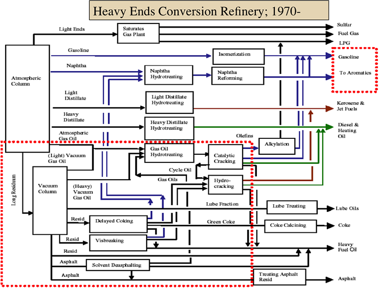
Figure 11.6 shows the configuration of the Heavy Ends Conversion refinery, with emphasis on processes marked with the red rectangle in Figure 11.6. These processes include hydrotreating of heavy gas oils before catalytic cracking to remove sulfur that contaminates downstream catalysts and to saturate aromatic C-C bonds to produce higher yields of fuel products from catalytic cracking. With better protection from sulfur contamination, FCC units can use modified catalysts to increase gasoline yield and reduce coke yield.
HECR offers four primary heavy oil or residue processing technologies as options for processing heavy crudes or “bottom-of-the barrel” processing. These processes have become more important as the world crude slate becomes heavier and more contaminated with sulfur and other heteroatom species, as sulfur limits become more stringent with environmental regulations.
Hydrocracking of heavy oils removes downstream catalyst contaminants and saturate aromatic compounds to produce higher yields of fuel products. Hydrocracking offers flexibility to choose between gasoline, jet fuel, and diesel fuel by coordinating the operations of fluid catalytic cracking and hydrocracking.
Other options for residue processing include coking, visbreaking, and deasphalting. Coking followed by catalytic upgrading of coking products (naphtha and gas oils) by hydrogenation, or hydrocracking generates high-quality distillates from residua that are not suitable for catalytic processes due to large concentrations of asphaltenes and heteroatom compounds (sulfur, nitrogen, oxygen, metals). Visbreaking and deasphalting removes the highly reactive compounds and asphaltenes from residua making the visbroken and deasphalted oils attractive feedstocks for catalytic hydroprocessing to produce distillate fuels.
The End of the 20th Century Refinery (the present-day refinery) is much more complex and versatile than its predecessor, The Catalytic Refinery. In addition, there are differences that are not so visible in conventional descriptions and flow sheets, such as computerized control of the operations and on-line measurements of product composition and properties.
Future Trends in Petroleum Refining
Future Trends in Petroleum Refining
Speculation about the future of refining is risky at best, but some trends are described as to be more certain by Self, Ekholm, and Bowers [5], as follows:
- Computers will increasingly be used for research, design, control and operation, maintenance, information handling, supply chain management, marketing execution, and distribution. As a result, research will broaden and manufacturing facilities will become more complex.
- The sophistication of competitors and customers, both domestic and international, will drive more transparent and efficient markets.
- Consumers will continue to search for energy sources that are reliable and independent of political forces, sustainable, environmentally acceptable, simple to generate and store and distribute, and inexpensive. Consequently, companies will hasten to reconcile the position of fossil fuels within emerging energy alternatives. Meanwhile, fuel formulations and usage will evolve, particularly for better performance and pollution prevention. This will progress despite the apparent trend of heavier crudes with increased sulfur, metals, solids, and water.
- Sensitivity will spread for the concerns and desires of consumers, communities, investors, and other stakeholders in all aspects of refining. Interaction with all stakeholders will be critical.
- Strategic consolidation of the size, number, and ownership of facilities and companies will continue. New partnerships will form among customers, competitors, and suppliers. Companies will attempt to maximize their return on assets, optimize allocation of capital, and reduce operating costs. In particular, efforts at hazard elimination and pollution prevention will intensify to reduce operational and liability costs.
Factors that may influence the future of petroleum refining
Factors that may influence the future of petroleum refining
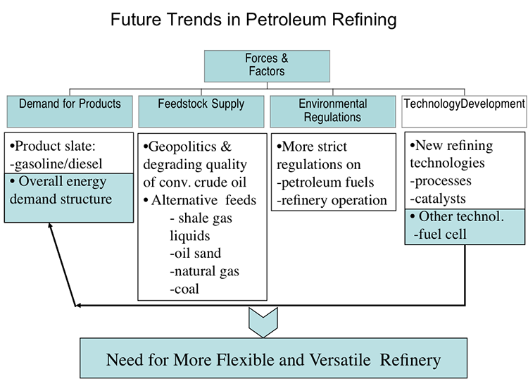
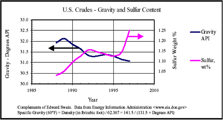
Figure 11.7 lists four factors that may influence the future of petroleum refining, including product demand, crude supply, environmental regulations, and new technology development. It is expected that in the near future, the demand for distillate fuels will keep increasing, while the conventional crude oil slate will become heavier and more contaminated. This conflict between the trends in supply and demand that is aggravated by stricter environmental regulations on the purity of fuels can be mitigated by new and more effective technologies (processes and catalysts). Although the conventional crude oils are becoming heavier (Figure 11.8), non-conventional liquids such as synthetic crude oil from oil sands in Canada and shale gas liquid by-products are lighter than the conventional crude oils and could be used as blend components to dilute the heavy crudes. Natural gas liquids and coal-derived liquids may also be used as alternative feedstocks for refining. The diversity in crude oil supply calls out the need to plan/operate a more flexible and versatile refinery.
Future Trends in Petroleum Refining
Forces and Factors
-Demand for products
Product slate: gasoline/diesel
Overall energy demand structure
-Feedstock supply
Geopolitics & degrading quality of conv. Crude oil
Alternative feeds: shale gas liquids, oil sand, natural gas, coal
-Environmental Regulations
More strict regulations on: petroleum fuels & refinery operations
-Technology Development
New refining technologies: processes & catalysts
Other technology: fuel cell
Need for more flexible and versatile Refinery!
[1.] F. Self, E. Ekholm, and K. Bowers, Refining Overview - Petroleum, Processes and Products, AIChE, 2000, Chapter 1.
Considerations for the Future Refinery
Considerations for the Future Refinery
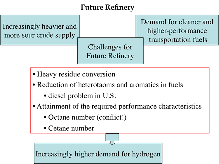
Figure 11.9 recaps some considerations for the future refinery, as discussed above, and lists the future challenges that include the need to process heavier and more contaminated crude oils to produce cleaner products than before. Production of diesel from highly aromatic by-product from FCC (LCO) remains a concern for the cost and quality of diesel fuel produced in the U.S. refineries. Also, extensive hydrotreatment to comply with the limits on heteroatom levels in fuels would negatively affect the octane numbers of gasoline because during hydrotreatment, olefins and aromatic compounds may be hydrogenated, thus reducing the octane number. No such conflict exists for diesel fuel, because cetane number of diesel actually increases with hydrogenation. It is clear that the hydrogen demand for the future refinery will keep increasing, and refineries will build or expand the existing hydrogen production capacity.
Future Refinery
-Increasingly heavier and more sour crude supply
-Demand for cleaner and higher-performance transportation fuels
-Challenges for future refineries
Heavy residue conversion
Reduction of heteroatoms and aromatics in fuels
Diesel problem in the US
Attainment of the required performance characteristics
Octane number (Conflict!)
Centane number
-Increasingly higher demand for hydrogen
Self-Check Questions
Please take a few minutes to work through the review questions. These questions will help you study for the final.
Assignments
Assignment Reminder
The assignments for this week include Exercise 10 and Quiz 4.
Exercise 10
Exercise 10 Instructions
- Draw a block flow diagram for a petroleum refinery that includes three different separation processes, five different conversion processes along with one or more finishing processes, and one supporting process to produce altogether nine commercial fuels and materials from a sour crude oil. Clearly label all the feedstocks, processes, and products on your diagram including the type of process (separation, conversion, finishing, and support) and the intermediate products. Make sure that all processes are correctly connected. Write down the principal objectives of this refinery. 60 pts
- Draw a block flow diagram for a petroleum refinery to maximize the diesel fuel yield from a paraffinic crude oil. In your flow diagram, include only the processes that are absolutely necessary for maximum diesel yield and make sure that the whole crude is converted completely to commercial (sellable) products in this refinery. 40 pts
Special Note:
You may use PowerPoint to draw the diagrams, or scan neatly hand-drawn diagrams and submit as a PDF to the Assignment.
Instructions for Submitting Response:
Once you have a solution to the exercises you will submit your answers as a PDF by uploading your file to be graded.
Please follow the instructions below.
- Find the Exercise 10 assignment in the Lesson 11 Module by either clicking Next until you find it or by clicking Assignments and scrolling down until you find it.
- Make sure that your name is in the document title before uploading it to the correct assignment (i.e. Lesson11_Exercise10_Tom Smith).
Quiz 4
Quiz 4. Will cover material in Lessons 10-11. Check the Syllabus, or Course Calendar for Quiz 4 schedule.
Summary and Final Tasks
Summary
The evolution of petroleum refinery can be considered to have taken in four stages from being just a separation refinery (distillation and dewaxing) to a conversion refinery in accordance with the demand for petroleum products. The conversion refinery evolved first as a thermal refinery with the development of thermal cracking, reforming, and polymerization, and transitioned into the catalytic refinery during World War II, with the development of processes such as catalytic cracking, catalytic reforming, alkylation, and catalytic hydrotreatment to define the finishing processes. The next stage of evolution after the catalytic refinery, high-end conversion refinery, has kept all the catalytic processes and added hydrocracking with emphasis on processing the heavy crude oils and production of cleaner fuels in compliance with environmental regulations. The increasing demand for hydrogen for hydrocracking and hydrotreatment operations and the need to recover increasing quantities of elemental sulfur highlighted the requirement of supporting processes for the operation of this refinery.
Learning Outcomes
- Comprehension of discrete stages in the history of petroleum refining and the driving forces that ushered in these stages.
- Evaluation of the driving forces that could impact the future of petroleum refineries and consideration of different scenarios for responding to the driving forces.
Reminder - Complete all of the Lesson 11 tasks!
| Readings: | F. Self, E. Ekholm, and K. Bowers, Refining Overview - Petroleum, Processes and Products, AIChE CD-ROM, 2000. |
|---|---|
| Assignment: | Exercise 10: Construct refinery flow diagrams. Quiz 4. Will cover material in Lessons10-11. Check the syllabus and course calendar for Quiz 4 schedule. |
Questions?
If you have any questions, please post them to our Help Discussion (not email), located in Canvas. I will check that discussion forum daily to respond. While you are there, feel free to post your own responses if you, too, are able to help out a classmate.