Coking
Coking
Despite the development of catalytic cracking processes, coking processes have survived as a popular refining process all over the world to refine the heavy end of crudes or heavy oils through carbon rejection as coke. Coking is the most severe thermal process used in the refinery to treat the very bottom-of-the-barrel of crude oil, i.e., vacuum residue.
Because of the high severity of thermal cracking during coking, the residue feed is completely converted to gas, light and medium distillates, and coke with no production of residual oil. Three different coking processes are used in the refineries: delayed coking, fluid coking, and flexi-coking (a variation of fluid coking). The common objective of the three coking processes is to maximize the yield of distillate products in a refinery by rejecting large quantities of carbon in the residue as solid coke, known as petroleum coke. Complete rejection of metals with the coke product provides an attractive alternative for upgrading the extra-heavy crude and bitumen, and that is particularly useful for initial processing of tar (or oil) sands for liberating the hydrocarbons from the sand that is left behind with the coke. Finding markets for the coke product as fuel or as filler for manufacturing anodes for the electrolysis of alumina (possible only with petroleum coke from delayed coking) makes the economics of coking more attractive by creating value for the rejected carbon. Sulfur and metal contents of the petroleum coke, as determined by the sulfur and metal contents of the residue feed, are two important factors that affect the commercial value of petroleum coke. Of the two coking processes, delayed coking is the preferred approach in many refineries that process heavy crudes.
Delayed Coking
Delayed Coking
Figure 6.6 shows a flow scheme in a delayed coking progress and a photograph of a delayed coking unit. The derricks above the drums that contain the drill stems are used to drill out the coke from the coke drums at the end of the coking cycle.
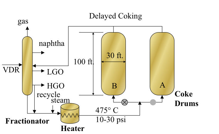
As shown in Figure 6.6, the residue feed is introduced to the fractionator after being heated in the heat exchangers with the coker gas oil products. The bottoms from the fractionator, including the heavy ends of the vacuum residue feed with heavy coker gas oil recycle, are mixed with steam and sent to the tubular heater in the furnace to be heated to approximately 475°C at a pressure of 10-30 psi. Steam is added to prevent coking in the heater, and the heated feed is introduced from the bottom of one of the coke drums. The coking takes place in the insulated coke drum as the drum fills up for a period of 16–18 h. While drum A is being filled up, drum B is decoked by using hydraulic cutters and the drilling stem, and the coke is removed from the bottom of the drum. As the coking in drum A is completed, drum B should be decoked, sealed, heated, and prepared for switching the feed. The coking cycle is controlled such that the vacuum residue is continuously fed to the unit (because the vacuum column works around the clock) and the fluid products are recovered continuously, while coke is removed intermittently in a semi-continuous process scheme. Therefore, there are at least two coke drums in every delayed coking unit, and some units have more than two drums. All of the heat necessary for coking is provided in the heater, whereas coking takes place in the coke drum; hence, the process is called “delayed coking.”
The hot product vapors and steam from the top of the drum are quenched by the incoming feed in the fractionator to prevent coking in the fractionator and to strip the lighter components of the vacuum residue feed. The fractionator separates the coking products into gasses, coker naphtha, coker light gas oil, and coker heavy gas oil. A side-steam stripper is used with the fractionator to ensure a good separation between the coker naphtha and light gas oil streams [2].
The delayed coking operating variables include heater outlet temperature, pressure, recycle ratio, and cycle time. These variables are selected based on feed properties such as the characterization factor, asphaltene content, and Conradson Carbon Residue (CCR) to ensure that coking in tubular heaters is minimized, and liquid product yield is maximized. The recycle ratio, which is typically 3–5%, is used to control the endpoint of the coker heavy gas oil. The coke yield can vary from 20% to 30% depending on the feed properties and coking conditions. In the textbook, you may find some proposed equations to predict coke and other product yields on the basis of the CCR of the vacuum residue and estimates of the distribution of sulfur in the feed among the coking products, suggesting that up to 30 wt% of the sulfur in the feed ends up in the coke, 30 wt% in the gas product, and 20 wt% in the coker heavy gas oil.
[2] Petroleum Refining, by J. H. Gary, G. E. Handwerk, M. J. Kaiser, 5th Edition, CRC Press NY, 2007, Chapter 5, pp.97-111.
Two Kinds of Coke
Two Kinds of Coke
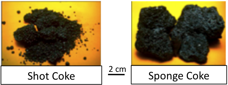
There are two kinds of coke produced by delayed coking of VDR: high-density shot coke, and porous sponge coke. Figure 6.7 shows the appearances of shot coke, consisting of aggregates of ~5 mm diameter spherical particles (resembling buckshots) and sponge coke (with a porous structure resembling a sponge). The formation of shot coke is usually troublesome because of difficulties in removing the coke from the drums and problems with grinding, although shot coke has some niche applications, such as in titanium dioxide (TiO2) production. Sponge coke is used as solid fuel, and manufacturing anodes for aluminum production, if its sulfur and metal concentrations are sufficiently low.
Among the delayed coking products, needle coke is a specialty coke produced mostly from coking of a highly aromatic FCC decant oil. The major properties of the needle coke include a low coefficient of thermal expansion, a low puffing (sudden volume expansion) tendency during graphitization because of lower nitrogen and sulfur contents, and high mechanical strength. The anode coke has limits on metal contaminants, requiring less than 500 ppm of Ni and V in the coke. The price of fuel coke depends on its carbon purity (S, N, and metal contaminants); however, the fuel coke is traded at a price comparable to that of coal.
Fluid and Flexi-Coking
Fluid and Flexi-Coking
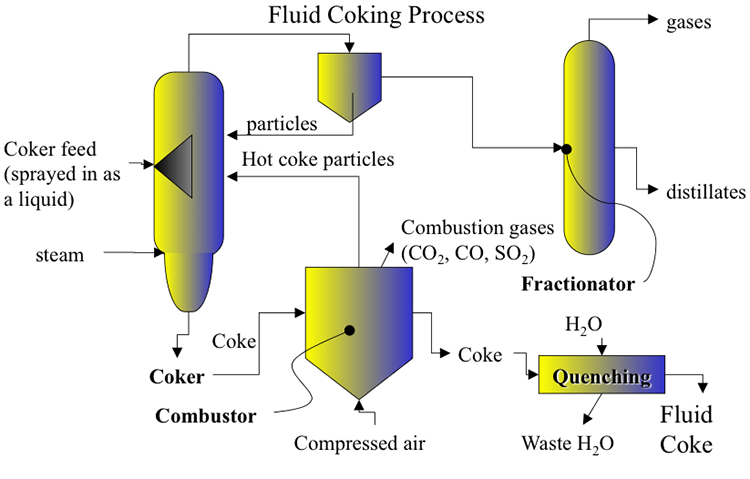
Fluid coking and flexi-coking are fluid-bed processes developed from the basic principles of FCC, with close integration of endothermic (cracking, coking, or gasification) and exothermic (coke burning) reactions. In fluid coking and flexi-coking processes, part of the coke product is burned to provide the heat necessary for coking reactions to convert vacuum residua into gasses, distillate liquids, and coke. Flexi-coking, as a variation of fluid coking, provides the options of partial or complete gasification of the coke product to produce a fuel gas with some or no coke in the product slate. Different from the bulk liquid-phase coking in delayed coking, coking takes place on the surface of circulating coke particles of coke heated by burning the surface layers of accumulated coke in a separate burner. Figure 6.8 shows a schematic flow diagram of the fluid coking process. The preheated vacuum residue is sprayed onto the hot coke particles heated in the burner by partial combustion of coke produced in the previous cycle. Using fluid beds in the reactor and burner provides efficient heat transfer and fast coking on a collectively large surface area of the small coke particles circulating between the reactor and burner. The products of coking are sent to a fractionator (similar to that used in delayed coking after recovery of fine coke particles). Steam is also added at the bottom of the reactor (not shown in the figure) in a scrubber to strip heavy liquids sticking to the surface of coke particles before they are sent to the burner. This steam also provides fluidization of coke particles in the reactor. The reactor and the burner operate at temperatures of 510–570°C and 595–675°C, respectively.
Higher temperatures and short residence times in the reactor lead to higher liquid and lower coke yields compared with those of delayed coking. Coke is deposited layer by layer on the fluidized coke particles in the reactor. Air is injected into the burner to burn 15–30 % of the coke produced in the reactor, part of the particles are returned to the reactor, and the remainder is drawn out as the fluid coke product. Fluid coking can process heavier VDR and gives a higher distillate yield (and lower coke yield) than delayed coking.
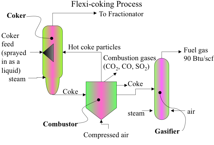
Figure 6.9 shows a schematic diagram of flexi-coking. A gasifier is added for conversion of some or all coke produced in the coker in reaction with air and steam to produce a synthesis gas. The hot coke particles from the combustor are circulated back to the coking reactor to provide the heat necessary for coking. The distillate products from the coker are sent to the fractionator, as is done in the fluid coking process. On the gasifier outlet, after removing the fine particles from the gas by cyclones, the gas is cooled in a direct-contact cooler to condense the sour water and recover the flexi-gas. The product gas can be used as fuel gas in the refinery. Depending on the demand, the flexi-coking process can produce both fluid coke and fuel gas, or gasify all the coke to produce only fuel gas.