Lesson 5: Geodetic Datums
The links below provide an outline of the material for this lesson. Be sure to carefully read through the entire lesson before returning to Canvas to submit your assignments.
Lesson 5 Overview
Overview
Despite the certainty of the physical surface of the Earth, it remains notoriously difficult to define in mathematical terms. The dilemma is illustrated by the ancient struggle to represent its curved surface on flat maps. There have been a whole variety of map projections developed over the centuries that rely on mathematical relationships between positions on the Earth's surface and points on the map. Each projection serves a particular application well, but none of them can represent the Earth without distortion.
As the technology of measurement has improved, the pressure for greater exactness in the definition of the Earth's shape has increased.
Plane surveying has traditionally relied on an imaginary flat reference surface, or reference frame (datum), with Cartesian axes. This rectangular system is used to describe measured positions by ordered pairs, usually expressed in northings and eastings, or y- and x- coordinates. Even though we have always known that this assumption of a flat earth is fundamentally unrealistic, it provided, and continues to provide, an adequate arrangement for small areas. The attachment of elevations to such horizontal coordinates somewhat acknowledges the topographic irregularity of the earth, but the whole system is always undone by its inherent inaccuracy as the area grow large. Even with electronic tools that widen the scope and increase the precision of the data, perfection is nowhere in sight.
The next lesson concerns some of the elements of the systems we inevitably use to accommodate the vagaries of assigning coordinates to the results of an earth-centered-earth-fixed positioning system based on signals from satellites.
Objectives
At the successful completion of this lesson, students should be able to:
- demonstrate understanding of the basics of geodetic coordinates;
- describe a few pertinent ideas about geodetic datums;
- describe plane surveying;
- recognize the structure of some geodetic coordinate systems;
- define the elements of a geodetic datum;
- discuss the geoid; and
- explain the North American Datum 1983.
Questions?
If you have any questions now or at any point during this week, please feel free to post them to the Lesson 5 Discussion Forum. (To access the forum, return to Canvas and navigate to the Lesson 5 Discussion Forum in the Lesson 5 module.) While you are there, feel free to post your own responses if you, too, are able to help out a classmate.
Checklist
Lesson 5 is one week in length. (See the Calendar in Canvas for specific due dates.) To finish this lesson, you must complete the activities listed below. You may find it useful to print this page out first so that you can follow along with the directions.
| Step | Activity | Access/Directions |
|---|---|---|
| 1 | Read the lesson Overview and Checklist. | You are in the Lesson 5 online content now. The Overview page is previous to this page, and you are on the Checklist page right now. |
| 2 | Read "A Few Pertinent Ideas about Geodetic Datums for GPS" in Chapter 5 pages 129 to 141 in GPS for Land Surveyors | Text |
| 3 | Read the lecture material for this lesson. | You are currently on the Checklist page. Click on the links at the bottom of the page to continue to the next page, to return to the previous page, or to go to the top of the lesson. You can also navigate the lecture material via the links in the Lessons menu. |
| 4 | Participate in the Discussion. | To participate in the discussion, please go to the Lesson 5 Discussion Forum in Canvas. (That forum can be accessed at any time by going to the GEOG 862 course in Canvas and then looking inside the Lesson 5 module.) |
| 5 | Read lesson Summary. | You are in the Lesson 5 online content now. Click on the "Next Page" link to access the Summary. |
GPS/GNSS and Geodesy
Hello! And welcome to Lesson Five in the course. This lesson will be about geodetic reference frames (datums), because it is not possible to use GPS/GNSS without engaging in geodesy.
Therefore, it is necessary to understand the native format of GPS/GNSS coordinates, and how the elements of geodesy influence those coordinates. Geodesy is a complicated subject, but we will be talking about just a few elements of the science.
GPS/GNSS and Geodesy
Today, GPS/GNSS has thrust us into the thick of geodesy, which is no longer the exclusive realm of distant experts. Thankfully, in the age of the microcomputer, the computational drudgery can be handled with software packages. Nevertheless, it is unwise to venture into GPS/GNSS believing that knowledge of the basics of geodesy is, therefore, unnecessary. It is true that GPS/GNSS would be impossible without computers, but blind reliance on the data they generate eventually leads to disaster.
Some Geodetic Coordinate Systems
Three-Dimensional (3-D) Cartesian Coordinates
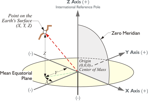
A spatial Cartesian system with three axes lends itself to describing the terrestrial positions derived from space-based geodesy. Using three rectangular coordinates instead of two, one can unambiguously define any position on the Earth, or above it for that matter. The three-dimensional Cartesian coordinates (x,y,z) derived from this system are known as Earth-Centered-Earth-Fixed (ECEF) coordinates. It is a right-handed orthogonal system that rotates with and is attached to the Earth, which is why it is called Earth fixed.
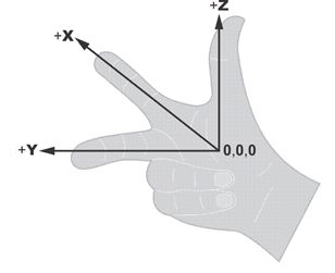
A three-dimensional Cartesian coordinate system is right-handed if it can be described by the following model: the extended forefinger of the right hand symbolizes the positive direction of the x-axis. The middle finger of the same hand extended at right angles to the forefinger symbolizes the positive direction of the y-axis. The extended thumb of the right hand, perpendicular to them both, symbolizes the positive direction of the z-axis.
But such a system is only useful if its origin (0,0,0) and its axes (x,y,z) can be fixed to the planet with certainty, something easier said than done.
This illustration shows the three-dimensional Cartesian coordinate system. It is possible to express a point on the Earth's surface in terms of these x, y, and z-coordinates in this Earth-Centered, Earth-Fixed, or ECEF system. This is the native system in which GPS/GNSS coordinates are expressed; obviously, the plane of the equator, the mean equatorial plane, and the zero meridian (aka Prime Meridian), are vital elements of this system. The usual arrangement is known as the Conventional Terrestrial Reference System (CTRS), and the Conventional Terrestrial System (CTS). The latter name will be used here. The origin is the center of mass of the whole Earth including oceans and atmosphere, the geocenter. Since the satellites orbit around the center of mass of the Earth, it is sensible to have the coordinate system derived from satellites with its origin at the center of mass. It can be used to define a position on the Earth's surface or, for that matter, a position above the Earth's surface. It is possible to have an XYZ coordinate in this system of an orbiting satellite. The x-axis is a line from that geocenter through its intersection at the zero meridian, also known as the International Reference Meridian (IRM), with the internationally defined conventional equator. The y-axis is extended from the geocenter along a line perpendicular from the x-axis in the same mean equatorial plane toward 90° East longitude. That means that the positive end of the y-axis intersects the actual Earth in the Indian Ocean. In any case, they both rotate with the Earth around the z-axis, a line from the geocenter through the internationally defined pole known as the International Reference Pole (IRP).
Polar Motion
The abstract idea of a three-dimensional coordinate system is perfect in the theoretical sense, but when you attach it to the actual, physical Earth, difficulties arise. For example, the Earth's rotational axis just won't hold still. The Earth wobbles so the z-axis of this Earth-Centered, Earth-Fixed three-dimensional Cartesian system is fixed by international agreement.The Earth is constantly moving, of course. While one can say that the Earth has a particular axis of rotation, equator, and zero meridian for an instant, they all change slightly in the next instant. Within all this motion, how do you stabilize the origin and direction of the three axes for the long term? One way is to choose a moment in time and consider them fixed to the Earth as they are at that instant.
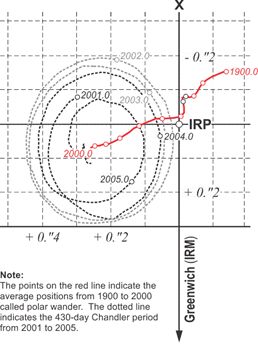
Here is an example of that process of definition. The Earth’s rotational axis wanders slightly with respect to the solid Earth in a very slow oscillation called polar motion. The largest component of the movement relative to the Earth’s crust has a 430-day cycle known as the Chandler period. It was named after American Astronomer Seth C. Chandler, who described it in papers in the Astronomical Journal in 1891. Another aspect of polar motion is sometimes called polar wander. The conventional terrestrial system of coordinates would be useless if its third axis was constantly wobbling. Originally, an average stable position was chosen for the position of the pole. Between 1900 and 1905, the mean position of the Earth’s rotational pole was designated as the Conventional International Origin (CIO) and the z-axis. This was defined by the Bureau International de l’Heure (BIH). It has since been refined by the International Earth Rotation Service, (IERS) using very long baseline interferometry (VLBI) and satellite laser ranging (SLR). It is now placed as it was midnight on New Year’s Eve 1983, or January 1, 1984 (UTC). The moment is known as an epoch and can be written 1984.0. So, we now use the axes illustrated. The name of the z-axis has been changed to the International Reference Pole, IRP epoch 1984, but it remains within 0.005” of the previous definition. It provides a geometrically stable and clear definition of the Earth’s surface for the z-axis.
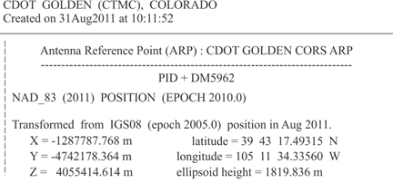
In this three-dimensional right-handed coordinate system, the x-coordinate is a distance from the y-z plane measured parallel to the x-axis. It is always positive from the zero meridian to 90º W longitude and from the zero meridian to 90º E longitude. In the remaining 180º, the X-coordinate is negative. The y-coordinate is a perpendicular distance from the plane of the zero meridian. It is always positive in the Eastern Hemisphere and negative in the Western Hemisphere. The z- coordinate is a perpendicular distance from the plane of the equator. It is always positive in the Northern Hemisphere and negative in the Southern Hemisphere. Here, above, is an example — the position of the station CTMC expressed in three-dimensional Cartesian coordinates of this type expressed in meters, the native unit of the system:
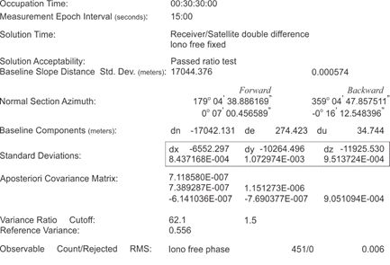
It is important to note that the GPS/GNSS Control Segment generates the position and velocity of the satellites themselves in ECEF coordinates. It follows that most modern GPS/GNSS software provides the GPS/GNSS positions in ECEF, as well. Further, the ends of baselines determined by GPS/GNSS observation are typically given in ECEF coordinates, so that the vectors themselves become the difference between those x, y, and z coordinates. The display of these differences as DX, DY, and DZ is a usual product of these post-processed calculations. This is the way that GPS/GNSS defines vectors. From these coordinates, it is possible to derive any number of other coordinates, i.e., Universal Transfers Mercater System coordinates, State Plane coordinates, latitude, and longitude. All these can be derived from the XYZ coordinates in the three-dimensional Cartesian Earth-Centered, Earth-Fixed system.
Latitude and Longitude
Despite their utility, such 3-D Cartesian coordinates are not the most common method of expressing a geodetic position. Latitude and longitude have been the coordinates of choice for centuries. The designation of these rely on the same two standard lines as 3D Cartesian coordinates: the mean equator and the zero meridian. Unlike them, however, they require some clear representation of the terrestrial surface. In modern practice, latitude and longitude cannot be said to uniquely define a position without a clear definition of the earth itself.
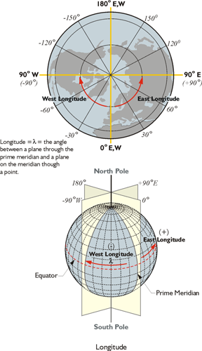
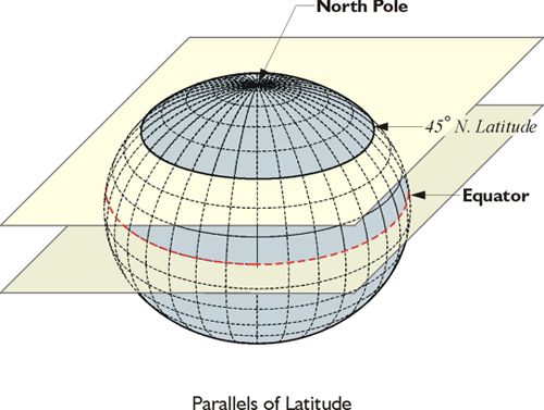
The Prime Meridian is through Greenwich, or approximately through Greenwich. West longitude is negative, is in our neck of the woods. East longitude going the other way around, meeting at the 180 degree longitudinal value. Longitude is usually symbolized by the Greek letter lambda. Latitude is measured from the equator north and south, north being positive and south negative. The plane in the illustration indicates 45 North latitude. There is more than one kind, more than one flavor, of latitude and longitude. In other words, a WGS84 (G1762) latitude and longitude is not the same as a NAD83(2011) latitude and longitude.
Elements of a Geodetic Reference Frame (Datum)
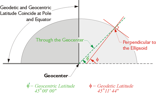
How can latitude and longitude not define a unique position on the Earth? The reference lines—the mean equator and the zero meridian—are clearly defined. The units of degrees, minutes, seconds, and decimals of seconds, allow for the finest distinctions of measurement. Finally, the reference surface is the Earth itself. The answer to the question relies, in the first instance, on the fact that there are several categories of latitude and longitude, the geographical coordinates. From the various options, astronomic, geocentric and geodetic. Their definition has a good deal to do with where down is.
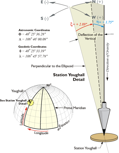
To begin that discussion of geodetic reference frames (datums), we'll talk about the deflection of the vertical. Please notice the astronomical coordinates of a station in the illustration. This is an actual station called Youghall in North America. The astronomic coordinates of that station, 40 degrees, 25 minutes, 36.28 seconds, differ from the geodetic coordinate, the latitude in that case being 40 degrees, 25 minutes, 33.39 seconds and the longitude in astronomic, 108 degrees, 46 minutes, 00.08 seconds, and the longitude in geodetic coordinate, 108 degrees, 45 minutes, 57.78 seconds. These coordinates differ because down is governed by gravity when it comes to astronomic coordinates. However, down is perpendicular to the ellipsoid for geodetic coordinates.
The ellipsoid is something that we're going to have to discuss. In shorthand terms, it is a smooth, mathematically determined representation of the Earth. It isn't plagued with the irregularities of the actual terrestrial surface, nor the irregularities of gravity. Please do not think that latitude and longitude coordinates are independent of the reference frame (datum) or independent of the ellipsoid that you are discussing.
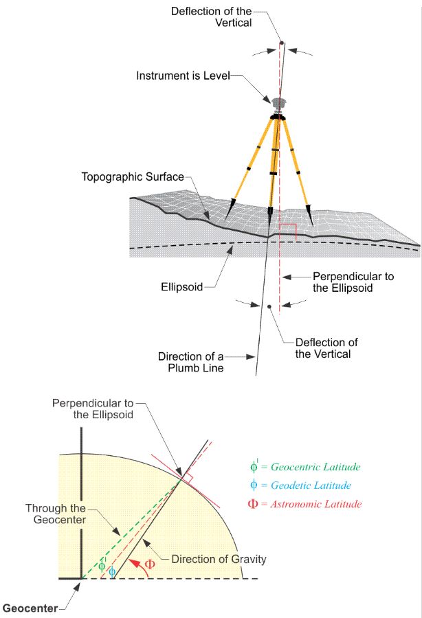
Here is an illustration, in the upper part we have an instrument that's set up on the Earth's topographic surface, and the red dashed line is perpendicular to the ellipsoid at its point, at the point where we find the instrument. The black line is the direction of down according to a plumb line (gravity), and the deflection of the vertical are the angles between them. However, the geodetic latitude, the version most used, is based upon down according to perpendicular to the ellipsoid, the red dashed line. Then, there's a third kind of latitude, the geocentric latitude. This is indicated by the line from the point on the Earth's surface to the geocenter, or the center of mass of the Earth (the green dashed line through the geocenter).
Geocentric, Geodetic, and Astronomic Latitude
Each can be extended upward, too, toward the zenith, and there are small angles between them. As mentioned, the difference between the vertical extension of a plumb line and the vertical extension of a line perpendicular to the ellipsoid is called the deflection of the vertical. It sounds better than the difference in down. Even though the discussion has so far been limited to latitude, the deflection of the vertical usually has both a north-south and an east–west component, so the deflection of the vertical has an effect on azimuths. There will be a slight difference between the azimuth of a GPS/GNSS baseline and the astronomically determined azimuth of the same line.
In one way of looking at it, GPS/GNSS is the reason that this issue has arisen so prominently in our work. Before GPS/GNSS existed, determination of latitude and longitude was done primarily with astronomic observations, which were done with optical instruments that were set up on the surface of the Earth. Imagine an optical surveying instrument set up over a point. If it is centered precisely with a plumb bob and leveled carefully, the plumb line and the line of the level telescope of the instrument are perpendicular to each other. In other words, the level line, the horizon of the instrument, is perpendicular to gravity. That optical instrument set up so carefully cannot be used to measure geodetic latitude and longitude directly, because they are not relative to the actual Earth. They are realtive to an ellipsoidal model of the Earth, and it is quite impossible to set up an instrument on that model. Furthermore, gravity does not even come into down on the model as it is perpendicular to the ellipsoidal surface at a particular point, whereas down is the direction of gravity at the point on the real Earth. They are most often not the same thing. Fortunately, the difference is usually small.
Nevertheless, using an instrument so carefully oriented to gravity, it is possible to determine the astronomic latitude and longitude of the point. Measuring the altitude of a circumpolar star is one good method of finding the latitude of the point from which the measurement is made. The measured altitude would be relative to the horizontal level line of the instrument, of course. One might expect that this astronomic latitude would be the same as the geocentric latitude of the point, but they are different. The difference is due to the fact that a plumb line coincides does not point to the center of the Earth where the line used to derive geocentric latitude originates. So there is a very long history indeed of geographical coordinates being derived from astronomic observations. Yet, the most commonly used coordinates are not astronomic latitudes and longitudes, but geodetic latitudes and longitudes. So, conversion to geodetic coordinates has a long history, too. Until the advent of GPS/GNSS, geodetic latitudes and longitudes were often values ultimately derived from astronomic observations by post-observation calculation. For example, the National Geodetic Survey and others corrected those coordinates and made them geodetic. In a sense conversion is still needed but GPS/GNSS receiver can display the geodetic latitude and longitude of a point to the user immediately because the calculations can be completed with incredible speed.
The fundamental fact remains unchanged: the instruments by which latitudes and longitudes are measured are oriented to gravity; the ellipsoidal model on which geodetic latitudes and longitudes are determined is not. And that is just as true for the antenna of a GPS/GNSS receiver, an optical surveying instrument, a camera in an airplane taking aerial photography, or even the GPS/GNSS satellites themselves. The most important point to carry away is this: latitudes and longitudes are dependent upon the reference frame (datum) on which they're measured. The secondary point is that, when we speak of latitude and longitude, we almost always mean geodetic latitude and longitude based upon an ellipsoidal model of the Earth.
Datums (Reference Frames)
The second part of the answer to the question posed earlier is this: if geographic coordinates are to have meaning they must have a context, a Reference Frame (Datum).
Despite the certainty of the physical surface of the Earth, the lithosphere, it remains notoriously difficult to define in mathematical terms. The dilemma is illustrated by the ancient struggle to represent its curved surface on flat maps. There have been a whole variety of map projections developed over the centuries that rely on mathematical relationships between positions on the Earth’s surface and points on the map. Each projection serves a particular application well, but none of them can represent the Earth without distortion. For example, no modern surveyor would presume to promise a client a high-precision control network with data scaled from a map. As the technology of measurement has improved, the pressure for greater exactness in the definition of the Earth’s shape has increased. Even with electronic tools that widen the scope and increase the precision of the data, perfection is nowhere in sight.
Development of the Ellipsoidal Model
The first step in representing positions on the Earth has always been the building of a model of the Earth.
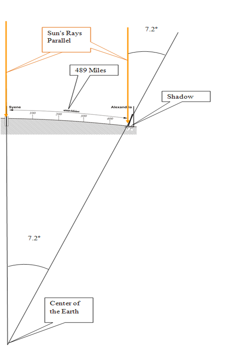
We have been trying to grasp that nature of the planet's size and shape for a long time. In 200 BC, Eratosthenes almost got the planet's circumference right, and, of course, the fundamental idea that it was in fact nearly a sphere. He knew that Syene was 489 miles south of Alexandria, the rope stretchers had measured it. In Syene at noon on midsummer there were no shadows and the sun was directly overhead and visible in the water at the bottom of a deep well. However, on the same day, a pillar did cast a shadow in Alexandria. The shadow formed an angle of 7.2 degrees. Therefore, Eratosthenes reasoned the angle between Alexandria and Syene at the center of the Earth had to be 7.2 degrees. That is 1/50th of 360 degrees. It followed that the circumference of the entire planet was 50 times 489 miles, or ~24,450 miles. This was an extraordinary deduction for 200 BC, and not so terribly far from right (~24,874 miles). Another leap forward occurred when Newton's thesis that the Earth was an ellipsoid rather than a sphere came in the first edition of his Principia in 1687.
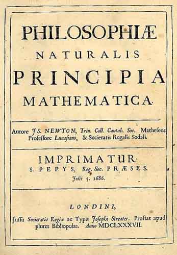
Newton’s idea that the actual shape of the Earth was slightly ellipsoidal was not entirely independent. There had already been some other suggestive observations. 15 years earlier, astronomer Jean Richer had found that to maintain the accuracy of the one-second clock he used in his observations in Cayenne, French Guiana, he had to shorten its pendulum significantly. The clock’s pendulum, regulated in Paris, tended to swing more slowly as it approached the equator. Newton reasoned that the phenomenon was attributable to a lessening of the force of gravity. Based on his own theoretical work, he explained the weaker gravity by the proposition, “the earth is higher under the equator than at the poles, and that by an excess of about 17 miles” (Philosophiae Naturalis Principia Mathematica, Book III, Proposition XX).
Obviously, if the Earth is to be more massive at the equator, bulging out at the equator, the Earth is ellipsoidal. It is like a squashed ball that bulges out in the middle. Although Newton’s model of the planet was supported by some of his contemporaries, notably Huygens, the inventor of Richer’s clock, it was attacked by others. The director of the Paris Observatory, Jean Dominique Cassini, for example, took exception to Newton’s concept. Even though the elder Cassini had himself observed the flattening of the poles of Jupiter in 1666, neither he nor his equally learned son Jacques were prepared to accept the same idea when it came to the shape of the Earth. It appeared they had some empirical evidence on their side.
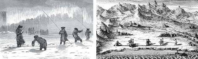
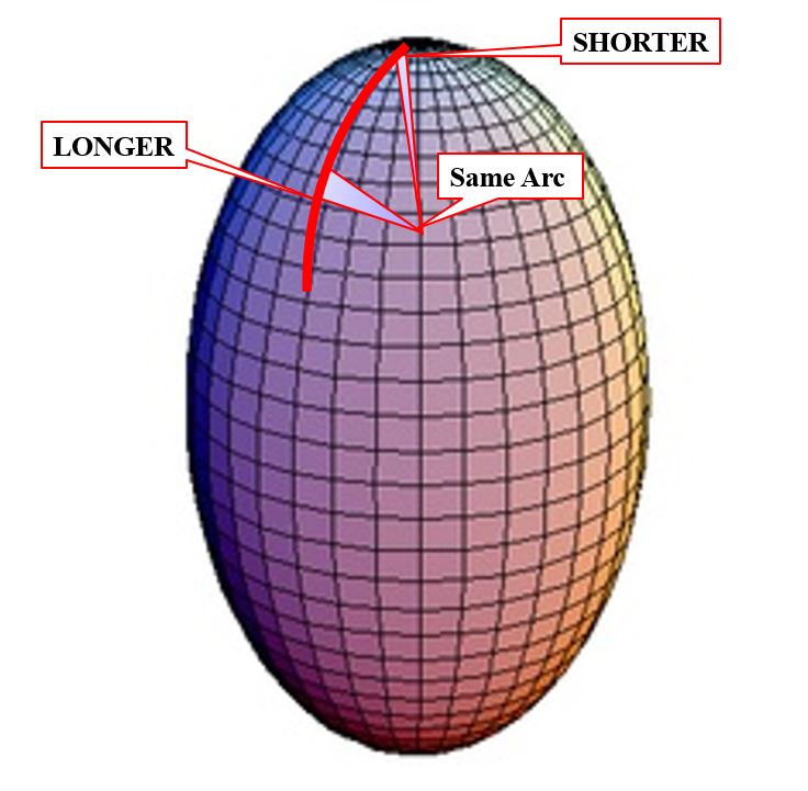
For geometric verification of the Earth model, scientists had employed arc measurements at various latitudes. Establishing the latitude of their beginning and ending points astronomically, they measured a north-south cardinal line to discover the length of one degree of longitude along a meridian arc. Early attempts assumed a spherical earth, and the results were used to estimate its radius by simple multiplication. In fact, one of the most accurate of the measurements of this type, begun in 1669 by the French Abbé J. Picard, was actually used by Newton in formulating his own law of gravitation. However, Cassini noted that close analysis of Picard’s arc measurement, and others, seemed to show the length of one degree of longitude actually decreased as it proceeded northward. He concluded that the Earth was not flattened as proposed by Newton, but was prolate, elongated at the poles.
The argument was not resolved until two expeditions between about 1733 and 1744 were completed. They were sponsored by the Paris Académie Royale des Sciences and produced irrefutable proof. One group which included Clairaut and Maupertuis was sent to measure a meridian arc near the Arctic Circle, 66°20' Nφ, in Lapland. Another expedition with Bouguer and Godin, to what is now Ecuador, measured an arc near the equator, 01°31' Sφ. Newton’s conjecture was proved correct, and the contradictory evidence of Picard’s arc was charged to errors in the latter’s measurement of the astronomic latitudes.
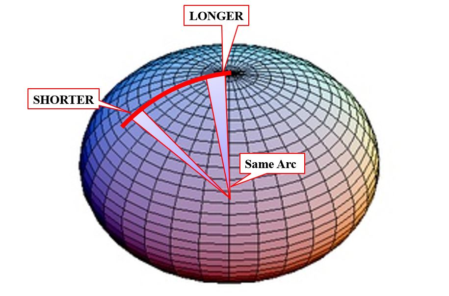
Eventually, these measurements proved Newton correct, and, in fact, the Earth is flattened at the poles or is an oblate ellipsoid.
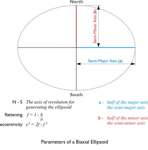
The ellipsoidal model bulging at the equator and flattened at the poles, has been used ever since as a representation of the general shape of the Earth’s surface. In fact, several reference ellipsoids have been established for various regions of the planet. They are precisely defined by their semi-major axis and flattening. The semi-major axis you see there in blue. It is half of the major axis of an ellipse. The semi-minor axis is half of the minor axis of the ellipse.
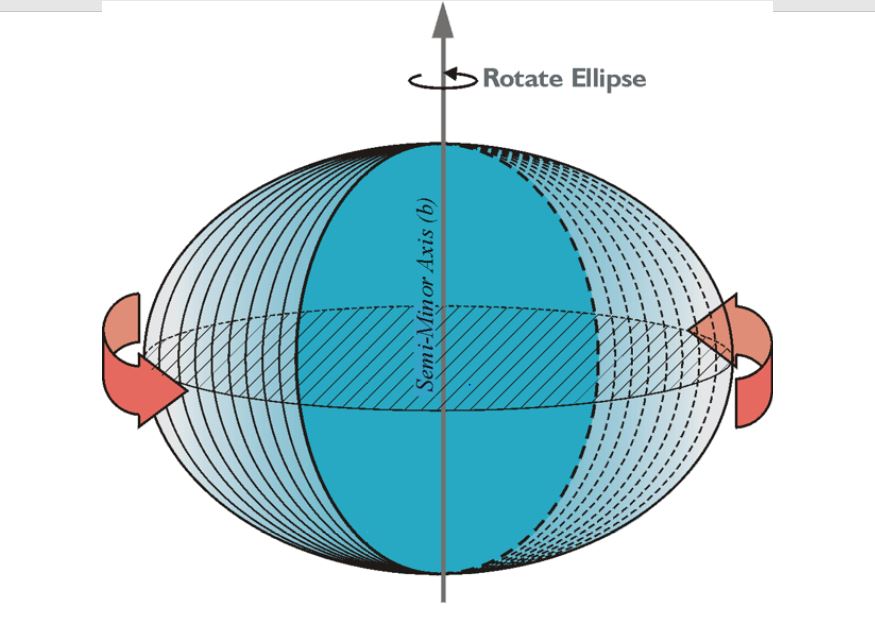
The ellipse can be rotated about the north-south semi-minor axis into the representation of a solid ellipsoid, in this case, a bi-axial ellipsoid. It bulges at the equator and is flattened at the poles.
NAD27
The Role of an Ellipsoid in a Datum
The semimajor axis and flattening can be used to completely define an ellipsoid of revolution. The ellipsoid is revolved around the minor axis. However, in the traditional approach, six additional elements are required if that ellipsoid is to become a geodetic datum: three to specify its center and three more to clearly indicate its orientation around that center. The Clarke 1866 spheroid is one of many reference ellipsoids. Its shape is completely defined by a semimajor axis, a, of 6378.2064 km and a flattening, f, of 1/294.9786982. It is the reference ellipsoid of the datum known as the North American Datum of 1927 (NAD27), but it is not the datum itself.
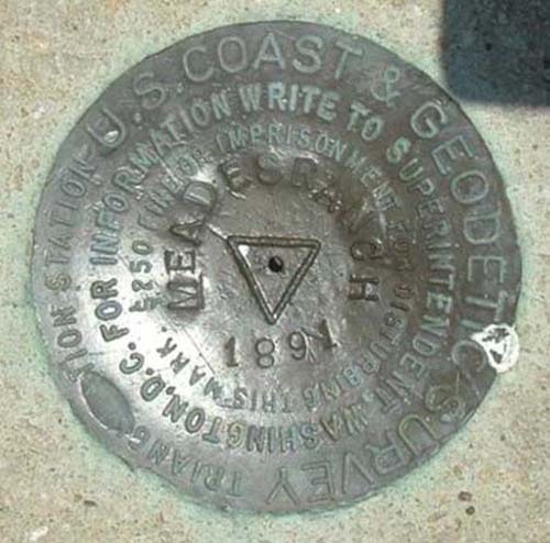
For the Clarke 1866 spheroid to become NAD27, the ellipsoid of reference had to be attached at a point and specifically oriented to the actual surface of the earth. However, even this ellipsoid, which fits North America well, could not conform to that surface perfectly. Therefore, the initial point was chosen near the center of the anticipated geodetic network to best distribute the inevitable distortion between the ellipsoid and the actual surface of the earth as the network extended beyond the initial point. The attachment was established at Meades Ranch, Kansas, 39°13'26".686 Nφ, 98°32'30".506 Wλ, and geoidal height was considered to be zero. Those coordinates were not sufficient, however. The establishment of directions from this initial point was required to complete the orientation.
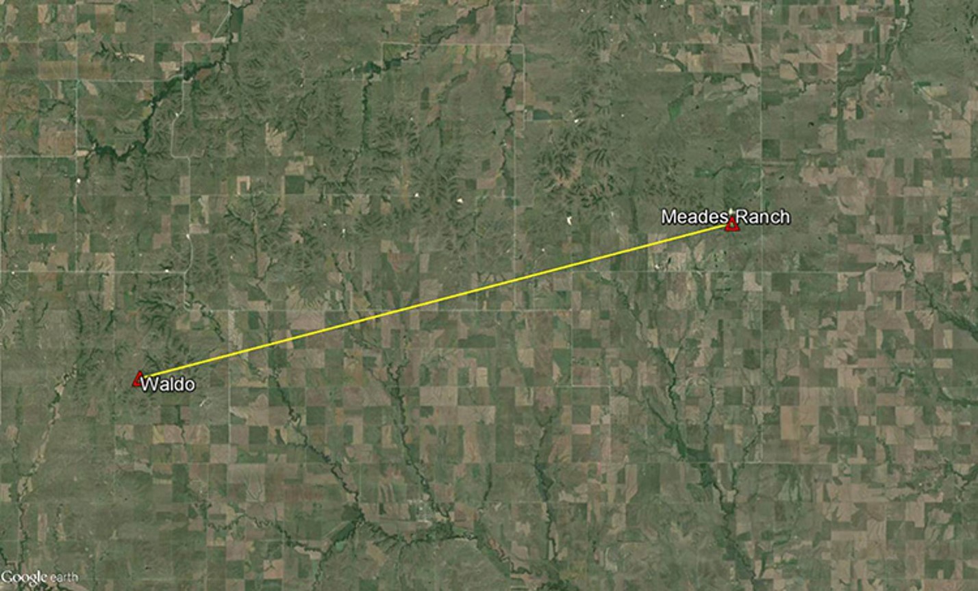
Azimuth from Meades Ranch to Waldo
The azimuth from Meades Ranch to station Waldo was fixed at 75°28'09".64 (from South) and the deflection of the vertical set at zero.
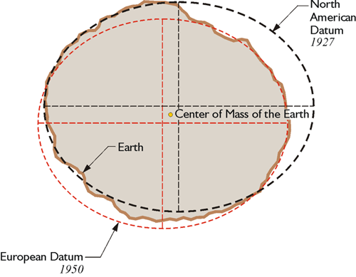
Once the initial point and directions were fixed, the whole orientation of NAD27 was established, including the center of the reference ellipsoid. Its center was imagined to reside somewhere around the center of mass of the earth. However, the two points were certainly not coincident, nor were they intended to be. In short, NAD27 does not use a geocentric ellipsoid.
Measurement Technology and Datum Selection
In the period before space-based geodesy was tenable, a regional datum was not unusual. The Australian Geodetic Datum 1966, the European Datum 1950, and the South American Datum 1969, among others, were also designed as nongeocentric systems. Achievement of the minimum distortion over a particular region was the primary consideration in choosing their ellipsoids, not the relationship of their centers to the center of mass of the earth. For example, in the Conventional Terrestrial System (CTS), the 3-D Cartesian coordinates of the center of the Clarke 1866 spheroid as it was used for NAD27 are about X = –4 m, Y = +166 m, and Z = +183 m. This approach to the design of datums was bolstered by the fact that the vast majority of geodetic measurements they would be expected to support were of the classical variety. That is, the work was done with theodolites, towers, and tapes. They were earth-bound. Even after the advent of electronic distance measurement, the general approach involved the determination of horizontal coordinates by measuring from point to point on the earth’s surface and adding heights, otherwise known as elevations, through a separate leveling operation. As long as this methodological separation existed between the horizontal and vertical coordinates of a station, the difference between the ellipsoid and the true earth’s surface was not an overriding concern. Such circumstances did not require a geocentric datum.
Geocentric Datum
However, as the sophistication of satellite geodesy increased, the need for a truly global, geocentric datum became obvious. The horizontal and vertical information were no longer separate. Since satellites orbit around the center of mass of the earth, a position derived from space-based geodesy can be visualized as a vector originating from that point. So, today, not only are the horizontal and vertical components of a position derived from precisely the same vector, the choice of the coordinate system used to express them is actually a matter of convenience. The position vector can be transformed into the 3-D Cartesian ECEF system, latitude, longitude and height, or virtually any other well-defined coordinate system. However, since the orbital motion and the subsequent position vector derived from satellite geodesy are themselves earth-centered, it follows that the most straightforward representations of that data are earth-centered as well.
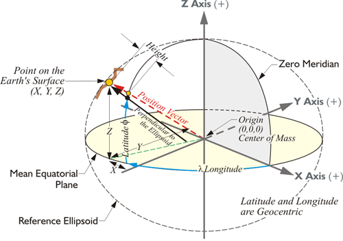
In this representation, there's a point on the Earth's surface. Its XYZ coordinates are indicated from the center of mass of the Earth in a three-dimensional Cartesian system.
However, there are some additions. For example, you see the longitude, symbolized by lambda from the Prime Meridian over to a point on the equatorial plane. From there, you see the latitude up to the position of this point as represented on the ellipsoid, the reference ellipsoid of the datum. Do you remember that an earlier representation of this, the original illustration along this line in the material, had no ellipsoid?
It was simply the XYZ coordinate axes. This is an important distinction. If we're going to have a latitude and longitude derived from an x, y, and z, we have to specify which ellipsoid and which datum (they are not the same thing), is involved. If we are working with the WGS 84 ellipsoid, then we get a latitude and longitude measured along the WGS84 ellipsoid. If we are working with the GRS 80 ellipsoid, we get a different latitude and longitude for exactly the same point on the Earth. If you change the shape of the ellipsoid, the latitude, and longitude changes. Also, the latitude and longitude of a point in the ITRF2014 (2010.0) reference frame is different than the latitude and longitude for the same point in NAD83 2011 (2010.0).
The position vector you see here in red from the center of mass up to the point is different than the black vector that's perpendicular to the ellipsoid. The black vector doesn't go to the center of mass. Also notice that if we're going to go from the position on the ellipsoid up to the actual surface of the Earth, we add a height, an ellipsoidal height. So, we can identify this position on the Earth's surface by an Earth-Centered, Earth-Fixed XYZ coordinate, or we can identify the same point with a geodetic latitude, and longitude, and height. These are just different coordinate systems for expressing the position of the point.
The Development of a Geocentric Model
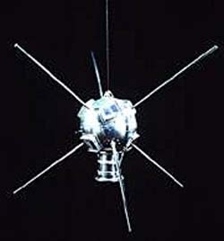
Satellites have not only provided the impetus for a geocentric datum, they have also supplied the means to achieve it. In fact, the orbital perturbations of man-made near-earth satellites have probably brought more refinements to the understanding of the shape of the earth in a shorter span of time than was ever before possible. For example, the analysis of the precession of Sputnik 2 in the late 1950s showed researchers that the earth’s semiminor axis was actually 85 meters shorter than had been previously thought. In 1958, while studying the tracking data from the orbit of Vanguard I, Ann Bailey of the Goddard Spaceflight Center discovered that the planet is shaped a bit like a pear. There is a slight protuberance at the North Pole, a little depression at the South Pole, and a small bulge just south of the equator. These formations and others have been discovered through the observation of small distortions in satellites’ otherwise elliptical orbits, little bumps in their road, so to speak. The deviations are caused by the action of Earth’s gravity on the satellites as they travel through space. Just as Richer’s clock reacted to the lessening of gravity at the equator, and thereby revealed one of the largest features of the earth’s shape to Newton, small perturbations in the orbits of satellites, also responding to gravity, reveal details of Earth’s shape to today’s scientists. The common aspect of these examples is the direct relationship between direction and magnitude of gravity and the planet’s form. In fact, the surface that best fits the earth’s gravity field has been given a name. It is called the geoid.
The Geoid

An often-used description of the geoidal surface involves idealized oceans. Imagine the oceans of the world utterly still, completely free of currents, tides, friction, variations in temperature and all other physical forces, except gravity. Reacting to gravity alone, these unattainable calm waters would coincide with the figure known as the geoid. Admitted by small frictionless channels or tubes and allowed to migrate across the land, the water would then, theoretically, define the same geoidal surface across the continents, too. Of course, the 70% of the earth covered by oceans is not so cooperative, nor is there any such system of channels and tubes. In addition, the physical forces eliminated from the model cannot be avoided in reality. The actual oceans of the Earth are affected by temperature, by wave motion, by salinity, and many other aspects that cause variation in their heights. These unavoidable forces actually cause Mean Sea Level to deviate from the geoid. It is a fact frequently mentioned to emphasize the inconsistency of the original definition of the geoid as it was offered by J.B. Listing in 1872. Listing thought of the geoidal surface as equivalent to Mean Sea Level. So even with tidal monitoring, Mean Sea Level is not an indicator of gravity alone, and that is the concept of the geoid. The geoid is that surface which is affected only by gravity, and it is an equipotential surface, where the gravity potential is always the same.
An Equipotential Surface
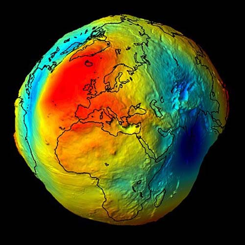
This somewhat exaggerated image shows what a lumpy surface, Earth would be if we only considered gravity. You can see that gravity isn't consistent across the entire topographic surface of the Earth. At every point it has a magnitude and a direction. In other words, anywhere on the earth, gravity can be described by a mathematical vector. Along the solid earth, such vectors do not have all the same direction or magnitude, but one can imagine a surface of constant gravity potential. Such an equipotential surface would be level in the true sense. It would coincide with the top of the hypothetical water in the previous example. Mean Sea Level does not define such a figure, nevertheless the geoidal surface is not just a product of imagination. For example, the vertical axis of any properly leveled surveying instrument and the string of any stable plumb bob are perpendicular to the geoid. Just as pendulum clocks and earth-orbiting satellites, they clearly show that the geoid is a reality.
I hasten to add that the ellipsoid, the nice, smooth, mathematical surface that we use as a reference surface in the definition of a datum, is different than the geoid. They are two different surfaces. The geoid is defined entirely by gravity and is a physical reality. The ellipsoid is a purely mathematical imaginary surface.
Three Figures
The geoid does not precisely follow mean sea level, nor does it exactly correspond with the topography of the dry land. It is irregular like the terrestrial surface. It is bumpy. Uneven distribution of the mass of the planet makes it maddeningly so, because if the solid earth had no internal anomalies of density, the geoid would be smooth and almost exactly ellipsoidal. In that case, the reference ellipsoid could fit the geoid to near perfection and the lives of geodesists would be much simpler. But like the earth itself, the geoid defies such mathematical consistency and departs from true ellipsoidal form by as much as 100 meters in places.
The Modern Geocentric Datum
Three distinct figures are involved in a geodetic datum for latitude, longitude, and height: the geoid, the reference ellipsoid, and the topographic surface. Due in large measure to the ascendancy of satellite geodesy, it has become highly desirable that they share a common center.
While the level surface of the geoid provides a solid foundation for the definitions of heights and the topographic surface of the earth is necessarily where measurements are made, neither can serve as the reference surface for geodetic positions.
From the continents to the floors of the oceans, the solid earth’s actual surface is too irregular to be represented by a simple mathematical statement. The geoid, which is sometimes under, and sometimes above, the surface of the earth, has an overall shape that also defies any concise geometrical definition. But the ellipsoid not only has the same general shape as the earth, but, unlike the other two figures, can be described simply and completely in mathematical terms.
Therefore, a global geocentric system has been developed based on the ellipsoid adopted by the International Union of Geodesy and Geophysics (IUGG) in 1979. It is called the Geodetic Reference System 1980 (GRS80). Its semimajor axis, a, is 6378.137 km long and is probably within a few meters of the earth’s actual equatorial radius. Its flattening, f, is 1/298.25722 and likely deviates only slightly from the true value, a considerable improvement over Newton’s calculation of a flattening ratio of 1/230. But then, he did not have orbital data from near-earth satellites to check his work.
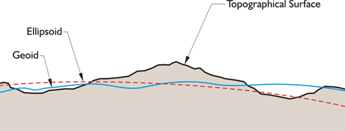
Here we have an image of three figures, one is the topographic surface of the Earth that we walk around on, and the next in the red dashed line is the ellipsoid, and the third in the blue wavy line is the geoid. The geoid doesn't follow mean sea level, doesn't correspond with a topographic surface. It's irregular. It does have peaks and valleys. It's bumpy because of the uneven mass of the planet. If the solid Earth didn't have these changes in density, the geoid and the ellipsoid would be the same thing. However, the geoid actually departs from the ellipsoid up to 100 meters in some places.
The figures involved in a latitude, and longitude, and height, are the geoid, the reference ellipsoid, and the Earth itself.
The goal is to have the reference ellipsoid, we use for satellite geodesy, to be geocentric. From the continents to the floors of the ocean, the solid Earth is too irregular to be represented by a simple mathematical statement. The geoid, sometimes under, sometimes above the surface of the Earth, has an overall shape that also defies any concise geometrical definition. However, the ellipsoid not only has the same general shape as the Earth, but unlike the other two figures can be described simply and completely in mathematical terms. That is why we use the ellipsoid as a reference. Therefore, a global geocentric system has been developed based on the ellipsoid adopted by the International Union of Geodesy and Geophysics. It's called the Geodetic Reference System, GRS 80.
Modern Geocentric Datum
| Ellipsoid | Semi-major axis | inverse flattening |
|---|---|---|
| GRS80 | 6,378,137 m | 298.257222101 |
| WGS84 | 6,378,137 m | 298.257223563 |
WGS84
In the table above, you have a comparison between WGS84 and GRS80 ellipsoids. You will notice that the semi major axis is the same, and the inverse flattening is only different when you get out to the sixth place to the right of the decimal. They are very similar. The WGS 84 ellipsoid is the reference of the datum known as the World Geodetic System 1984 (WGS84). In other words, the WGS 84 ellipsoid attached at the center of mass of the Earth is one component of the WGS84 datum, but please note that while the WGS84 ellipsoid is the reference ellipsoid for the WGS84 datum - it is not the datum itself.
The WGS84 datum (reference frame) has been used by the U.S. Military since January 21, 1987. There have been six incarnations of WGS84 since then. While WGS84 has always been the basis for the GPS Navigation message, the particular version of the datum has changed. As of this writing, the latest version of WGS84 is WGS84 (G1762). The number following the letter G is the number of the GPS week during which the coordinates first were used in the National Geospatial Intelligence Agency, NGA, precise ephemeris estimations. Therefore, coordinates provided today by GPS receivers are based in WGS84 (G1762) which is the sixth update to the realization of the WGS84 Reference Frame. The original WGS 84 was based on observations from more than 1900 Doppler Stations. It was revised to become WGS84 (G730) to incorporate GPS observations. That realization was implemented in GPS by the Operational Control Segment, OCS on June 29, 1994. More GPS based realizations of WGS84 followed, WGS84 (G873) on January 29, 1997, and WGS84 (G1150) was implemented on January 20, 2002 and WGS84(G1674) on February 8, 2012. Today, the epoch of WGS84 is (G1762).
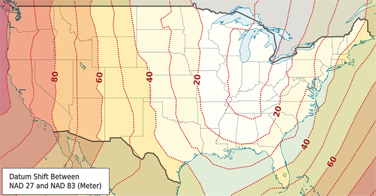
Most available GPS software can transform those coordinates to a number of other datums as well. The one that is probably of greatest interest in the United States today is the North American Datum 1983 (NAD83). Originally, the difference between WGS84 as originally rolled out in 1987 and NAD83 as first introduced in 1986 coordinates was so small that transformation was unnecessary. That is no longer the case when it comes to NAD83 2011 (2010.0) and WGS84 (G1762) the difference can be ~1 to 2 meters.
North American Datums
NAD27
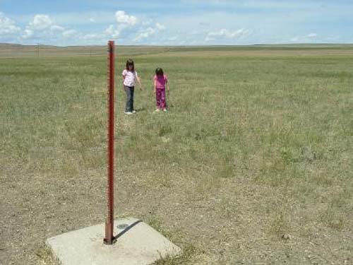
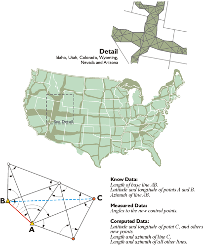
The Clarke 1866 ellipsoid was the foundation of NAD27, and the blocks that built that foundation were made by geodetic triangulation. After all, an ellipsoid, even one with a clearly stated orientation to the earth, is only an abstraction until physical, identifiable control stations are available for its practical application. During the tenure of NAD27, control positions were tied together by tens of thousands of miles of triangulation and some traverses. Its measurements grew into chains of figures from Canada to Mexico and coast to coast, with their vertices perpetuated by bronze disks set in stone, concrete, and other permanent media. These tri-stations, also known as brass caps, and their attached coordinates have provided a framework for all types of surveying and mapping projects for many years. They have served to locate international, state, and county boundaries. They have provided geodetic control for the planning of national and local projects, development of natural resources, national defense, and land management. They have enabled surveys to be fitted together, provided checks, and assisted in the perpetuation of their marks. They have supported scientific inquiry, including crustal monitoring studies and other geophysical research. But even as application of the nationwide control network grew, the revelations of local distortions in NAD27 were reaching unacceptable levels. The work was excellent, and given the technology of the day, remarkable but judged by the standards of newer measurement technologies, the quality of some of the observations used in the datum were too low. That, and its lack of an internationally viable geocentric ellipsoid, finally drove its positions to obsolescence. The monuments remain, but it was clear early on that NAD27 had some difficulties. There were problems from too few baselines, Laplace azimuths and other deficiencies. By the early 1970s, the NAD27 coordinates of the national geodetic control network were no longer adequate.
The Development of NAD 83
While a committee of the National Academy of Sciences advocated the need for a new adjustment in its 1971 report, work on the new datum, NAD83, did not really begin until after July 1, 1974. Leading the charge was an old agency with a new name. Called the U.S. Coast & Geodetic Survey in 1878, and then the Coast and Geodetic Survey (C&GS) from 1899, the agency is now known as the National Geodetic Survey (NGS). It is within the National Oceanic and Atmospheric Administration (NOAA). The first ancestor of today’s NGS was established back in 1807 and was known as the Survey of the Coast. Its current authority is contained in U.S. Code, Title 33, USC 883a.
NAD83 includes not only the United States, but also Central America, Canada, Greenland, and Mexico. The NGS and the Geodetic Survey of Canada set about the task of attaching and orienting the GRS80 ellipsoid to the actual surface of the earth, as it was defined by the best positions available at the time. It took more than 10 years to readjust and redefine the horizontal coordinate system of North America into what is now NAD83. More than 1.7 million weighted observations derived from classical surveying techniques throughout the Western Hemisphere were involved in the least-squares adjustment. They were supplemented by approximately 30,000 EDM measured baselines, 5000 astronomic azimuths, and more than 650 Doppler stations positioned by the TRANSIT satellite system. Over 100 Very Long Baseline Interferometry (VLBI) vectors were also included. GPS, in its infancy, was not utilized significantly.
GPS was growing up in the early 80’s and some of the agencies involved in its development decided to join forces. NOAA, the National Aeronautics and Space Administration (NASA), the U.S. Geological Survey (USGS), and the Department of Defense coordinated their efforts. As a result, each agency was assigned specific responsibilities. NGS was charged with the development of specifications for GPS operations, investigation of related technologies, and the use of GPS for modeling crustal motion. It was also authorized to conduct its subsequent geodetic control surveys with GPS. So, despite an initial sparseness of GPS data in the creation of NAD83, the stage was set for a systematic infusion of its positions as the datum matured. GPS, through efforts of several agencies, began to be used more and more. It was clear that it was going to contribute more positions and refinement of the datum as time went on.
The International Terrestrial Reference System (ITRS)
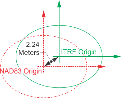
As NAD83 has aged, there has been constant improvement in geodesy. When NAD83 was created, it was intended to be geocentric. It is known that the center of the reference ellipsoid of NAD83, GRS80, is about 2.24 meters from the true geocenter. However, there is a reference system that is geocentric. It is known as the International Terrestrial Reference System, ITRS. The reference frame derived from it is the International Terrestrial Reference Frame (ITRF). Its origin is at the center of mass of the whole earth, including the oceans and atmosphere. The unit of length is the meter. The orientation of its axis was established as consistent with that of the IERS’s predecessor, Bureau International de l’Heure, BIH, at the beginning of 1984.
Today, the ITRF is maintained by the International Earth Rotation Service (IERS), which monitors Earth Orientation Parameters (EOP) for the scientific community through a global network of observing stations. This is done with GPS, Very Long Baseline Interferometry (VLBI), Lunar Laser Ranging (LLR), Satellite Laser Ranging (SLR), the Doppler Orbitography and Radiopositioning Integrated by Satellite (DORIS), and the positions of the observing stations are considered to be accurate to the centimeter level. Recognizing that the several hundred control stations worldwide for which it publishes yearly coordinates are actually in motion due to the shifting of approximately 20 tectonic plates worldwide, the IERS also provides velocities for them. The International Terrestrial Reference Frame is actually a series of realizations. The first was in 1988. In other words, it is revised and published on a regular basis.
The vectors that you see on this illustration indicate the motion of the tectonic plates. You can see the legend there, the length of two centimeters per year. It shows the directions that these tectonic plates are in motion relative to the center of mass of the Earth.
ITRF2014, WGS84 and NAD83
The North American Datum of 1983 (NAD83) is used everywhere in North America except Mexico. The latest realization of the datum as of this writing is NAD83 (2011) epoch 2010.0. This realization in the coterminous United States and Alaska is available through the National CORS (Continuously Operating Reference Stations). Their number of National CORS and Cooperative CORS sites continuously grows with the addition of several new stations each month.
| Year | Realization (Epoch) | For all practical purposes equivalent to: |
|---|---|---|
| 1987 | WGS 1984 (ORIG) | NAD83 (1986) |
| 1994 | WGS84 (G730) | ITRF91/92 |
| 1997 | WGS84 (G873) | ITRF94/96 |
| 2002 | WGS84 (G1150) | ITRF00 |
| 2012 | WGS (G1674) | ITRF08 |
| 2013 | WGS (G1762) | Compares to ITRF08 and ITRF2014 within 1cm Root Mean Square (RMS) overall if the epochs are the same |
As mentioned earlier, in the past we did not have to be concerned with the shift between NAD83 (1986) and WGS84 as introduced in 1987, because the discrepancy easily fell within our overall error budget. NAD83 and WGS84, originally, differed by only a centimeter or two. That is no longer true. In their new definitions—NAD83 (2011) and WGS84 (G1762)—differ up to one or two meters within the continental United States. On the other hand, ITRF08, ITRF2014 and WGS84 (G1762) are virtually identical if their epochs (moment in time) are the same. The typical standard epoch for both are WGS84(G1762) and ITRF08 is 2005.0. The typical standard epoch for both ITRF2014 is 2010.0; NGS has developed a program called Horizontal Time Dependent Positioning (HTDP) to transform positions from one epoch to another. In other words, this program allows the movement of positions from one date to another, transformation from one reference frame to another and supports the recent realizations of the NAD 83, ITRF and WGS84. This underlines the fact that ITRF and WGS84 systems are global, and their realizations take into account that the earth is in constant motion due to the shifting of tectonic plates around the world. However, NAD83 is fixed to one plate, the North American plate, and moves with it. Consequently, NAD83, in the continental United States moves approximately 10 to 20 millimeters per year in relation to the realizations of ITRF and WGS84 reference frames
The Management of NAD83
Since geodetic accuracy with GPS depends on relative positioning, surveyors continue to rely on NGS stations to control their work, just as they have for generations. Today, it is not unusual for surveyors to find that some NGS stations have published coordinates in NAD83 and others, perhaps needed to control the same project, only have positions in NAD27. In such a situation, it is often desirable to transform the NAD27 positions into coordinates of the newer datum. But, unfortunately, there is no single-step mathematical approach that can do it accurately. The distortions between the original NAD27 positions are part of the difficulty. The older coordinates were sometimes in error as much as 1 part in 15,000. Problems stemming from the deflection of the vertical, lack of correction for geoidal undulations, low-quality measurements, and other sources contributed to inaccuracies in some NAD27 coordinates that cannot be corrected by simply transforming them into another datum.
Transformations from NAD27 to NAD83
Nevertheless, various approximate methods are used to transform NAD27 coordinates into NAD83 values. For example, the computation of a constant local translation is sometimes attempted using stations with coordinates in both systems as a guide. Another technique is the calculation of two translations, one rotation and one scale parameter, for particular locations based on the latitudes and longitudes of three or more common stations. Perhaps the best results derive from polynomial expressions developed for coordinate differences, expressed in Cartesian or ellipsoidal coordinates using a 3-D Helmert transformation. However, besides requiring seven parameters (three shift, one scale, and three rotation components) this approach is at its best when ellipsoidal heights are available for all the points involved. Where adequate information is available, software packages such as the NGS program NADCON can provide coordinates.
Even if a local transformation is modeled with these techniques, the resulting NAD27 positions might still be plagued with relatively low accuracy. The NAD83 adjustment of the national network is based on nearly 10 times the number of observations that supported the NAD27 system. This larger quantity of data, combined with the generally higher quality of the measurements at the foundation of NAD83, can have some rather unexpected results. For example, when NAD27 coordinates are transformed into the new system, the shift of individual stations may be quite different from what the regional trend indicates. In short, when using control from both NAD83 and NAD27 simultaneously on the same project, surveyors have come to expect difficulty.
In fact, the only truly reliable method of transformation is not to rely on coordinates at all, but to return to the original observations themselves. It is important to remember, for example, that geodetic latitude and longitude, as other coordinates, are specifically referenced to a given datum (reference frame) and are not derived from some sort of absolute framework. But the original measurements, incorporated into a properly designed least-squares adjustment, can provide most satisfactory results.
Densification and Improvement of NAD83
The inadequacies of NAD27 and even NAD83 positions in some regions are growing pains of a fundamentally changed relationship. In the past, relatively few engineers and surveyors were employed in geodetic work. Perhaps the greatest importance of the data from the various geodetic surveys was that they furnished precise points of reference, to which the multitude of surveys of lower precision could then be tied. This arrangement was clearly illustrated by the design of state plane coordinates systems, devised to make the national control network accessible to surveyors without geodetic capability. However, the situation has changed. The gulf between the precision of local surveys and national geodetic work is virtually closed by GPS, and that has changed the relationship between local surveyors in private practice and geodesists. For example, the significance of state plane coordinates as a bridge between the two groups has been drastically reduced. Today’s surveyor has relatively easy and direct access to the geodetic coordinate systems themselves through GPS. In fact, the 1- to 2-ppm probable error in networks of relative GPS-derived positions frequently exceed the accuracy of the NAD83 positions intended to control them.
High Accuracy Reference Networks
Other significant work along this line was accomplished in the state-by-state super-net programs. The creation of High Accuracy Reference Networks (HARN) were cooperative ventures between NGS and the states, and often include other organizations as well. The campaign was originally known as High Precision Geodetic Networks (HPGN). A station spacing of not more than about 62 miles and not less than about 16 miles was the objective in these statewide networks. The accuracy was intended to be 1 part-per-million, or better, between stations. In other words, with heavy reliance on GPS observations, these networks were intended to provide extremely accurate, vehicle-accessible, regularly spaced control point monuments with good overhead visibility. These stations were intended to provide control superior to the vectors derived from the day-to-day GPS observations that are tied to them. In that way, the HARN points provide the user with a means to avoid any need to warp vectors to fit inferior control. That used to some time happen in the early days of GPS. To further ensure such coherence in the HARN, when the GPS measurements were complete, they were submitted to NGS for inclusion in a statewide readjustment of the existing NGRS covered by the state. Coordinate shifts of 0.3 to 1.0 m from NAD83 values were typical in these readjustments, which were concluded in 1998. The most important aspect of HARN positions was the accuracy of their final positions.
The original NAD83 adjustment is indicated with a suffix including the year 1986 in parentheses, that is, NAD83 (1986). However, when a newer realization is available, the year in the parentheses will be the year of the adjustment. The most recent realization is NAD83 (2011).
CORS
Continuously Operating Reference Stations (CORS)
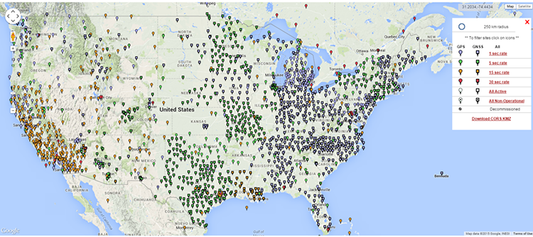
In about 1992, the NGS began establishing a network of Continuous Operating Reference Stations (CORS) throughout the country. The original idea was to provide positioning for navigational and marine needs. There were about 50 CORS in 1996. Their positional accuracies are 3 cm horizontal and 5 cm vertical. They also must meet NOAA geodetic standards for installation, operation, and data distribution. Today, there are thousands of Continuously Operating Reference Stations (CORS) online. From 1998 to 2004, NGS introduced another series of observations in each state designed to tie the network to the Continuously Operating Reference Stations, CORS. This work resulted in the Federal Base Network (FBN), which is a nationwide network of monumented stations. These spatial reference positions are among the most precise available and are particularly dense in crustal motion areas. In general, these points are spaced at approximately 100 kilometers apart. The accuracies intended are: 1 cm-latitudes and longitudes, 2 cm-ellipsoidal heights, and 3 cm-orthometric heights. These stations are few compared to the much more numerous Cooperative Base Network (CBN). This is a high-accuracy network of monumented control stations spaced at 25 to 50 km apart throughout the United States and its territories. The CBN was created and is maintained by state and private organizations with the help of NGS. The Continuously Operating Reference Stations in the NGS network are mostly to provide support for carrier phase observations. Information is available for postprocessing on the Internet. The coordinates of the CORS are currently available in ITRF2014 (2010.0 and NAD83 2011 (2010.0)
Discussion
Discussion Instructions
To continue the discussion begun by this lesson, I would like to pose this question:
What are differences between the geoid, the ellipsoid, and the physical surface of the earth? What role do each of them play regarding the collection and expression in coordinates of GPS positions?
To participate in the discussion, please go to the Lesson 5 Discussion Forum in Canvas. (That forum can be accessed at any time by going to the GEOG 862 course in Canvas and then looking inside the Lesson 5 module.)
Summary
Three distinct figures are involved in a geodetic datum for latitude, longitude and height: the geoid, the reference ellipsoid, and the Earth itself. Due in large measure to the ascendancy of satellite geodesy, it has become highly desirable that they share a common center.
While the level surface of the geoid provides a solid foundation for the definitions of heights and the topographic surface of the Earth is necessarily where measurements are made, neither can serve as the reference surface for geodetic positions. From the continents to the floors of the oceans, the solid Earth's actual surface is too irregular to be represented by a simple mathematical statement.
The geoid, which is sometimes under, and sometimes above, the surface of the Earth, has an overall shape that also defies any concise geometrical definition. But the ellipsoid not only has the same general shape as the Earth, but, unlike the other two figures, can be described simply and completely in mathematical terms.
A good understanding of these ideas is essential to clear comprehension of satellite based positioning. The next lesson will focus on the most usual manifestations of GPS coordinates in the United States, State Plane Coordinates and UTM coordinates. We will also have a bit of discussion on an often misunderstood topic- heights.
Before you go on to Lesson 6, double-check the Lesson 5 Checklist to make sure you have completed all of the activities listed there.