The term CONOP means a complete description of the mission that a UAS operation goes through from launch to recovery. The CONOP includes a procedure for the mission to be carried out to achieve the mission objectives. The procedure depends on the system configuration and capabilities. UAS capabilities determined by its components such as sensors, guidance, endurance (in time), weather limitations (ceilings, wind speeds, etc.), navigation and control play key role in defining the CONOP. CONOP may also depend on other factors such as safety considerations for the UAS as well as to lives and properties along the flying path of the mission. The procedure will also include weather condition such as wind speed and visibility, as the mission may be halted or terminated if the favorable weather condition is not reached.
The FAA expectations from the provided CONOP are:
- to give FAA clear understanding of the proposed operations;
- to include:
- description of UAS;
- details of intended use;
- proposed area of operations;
- intended classes of Airspace.
- to enable or to include the development of the Operational Risk Assessment (ORA).
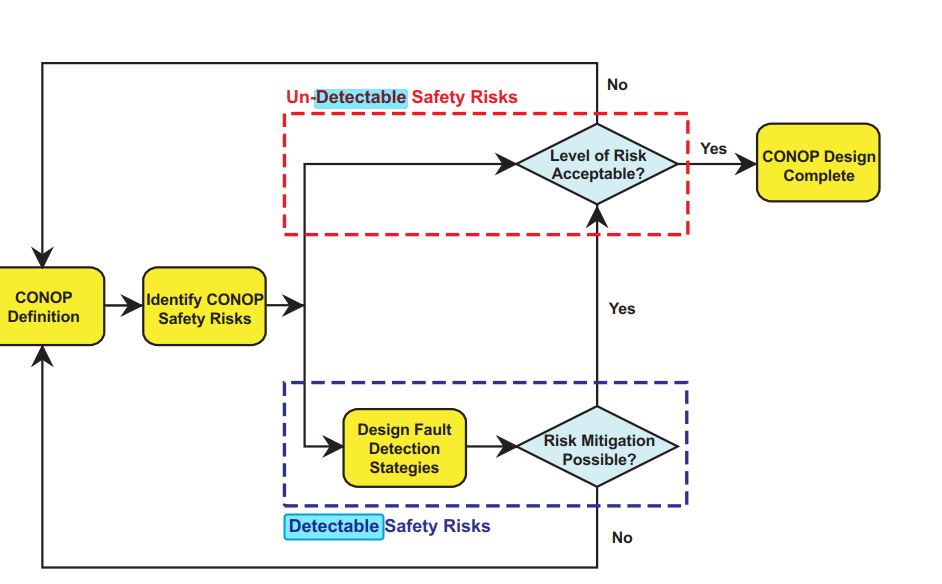
There are many ways to design CONOP one of which is described in the final report published by the ITS Research Institute of the University of Minnesota entitled “Analysis of Unmanned Aerial Vehicles Concept of Operations in ITS Applications”. In that report, the process describes the following main elements of the design:
- CONOP Definition
- Identification of CONOP Safety Risks
- Designing Fault Detection Strategies
Figure 3.1 illustrates a flow chart for small UAS concept of operation (CONOP) design process.
Many details need to be identified to complete CONOP development. Information such as:
- What are the known elements and the high-level capabilities of the system?
- What are the geographical and physical extents of the mission under execution?
- What is the time-sequence of activities that will be performed?
- What resources are needed to design, build, or retrofit the system?
- Which kind of risks are associated with different components of the system?
The block diagram in Figure 3.2 illustrates the components that make up most of the UASs available in the market today. Such a diagram is very beneficial to CONOP analysis and development, as it lists all the sub-systems included in a UAS. As you can see below, the main components that concern us in this course are the mission sensor payload, airborne data link, and navigation and control sensors. The mission sensor payload represents the highest priority for geospatial data users. Types and quality of sensors within the mission sensor payload block are directly linked to the end user's needs and expectations. The other two blocks, the airborne data link and navigation and control sensors, mainly concern the FAA and its regulations. Main FAA concerns lie in the quality of the communications and the navigational systems that steer and control the aircraft.
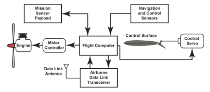
At the center of this schematic drawing is a rectangle containing the words “Flight Computer.” Arrows leave the Flight Computer from the left, the right, and from its top and bottom.
From the right, an arrow points to a smaller rectangle with rounded corners that contains the words “Motor Controller.” A subsequent arrow leaves the left side of the Motor Controller and points to a labeled drawing of the engine.
From the right of the Flight Computer, an arrow points to a smaller rectangle with rounded corners that contains the words “Control Servo.” The Control Servo is attached with a thin line to a drawing of an aircraft, which is labeled “Control Surface.”
From the bottom of the Flight Computer, an arrow points to a rectangle entitled “Airborne Data Link Tranceiver.” From the Airborne Data Link Tranceiver, an arrow points back to the Flight Computer. The Airborne Data Link Tranceiver has a small “Data Link Antenna” attached.
One arrow leaves the top of the Flight Computer. It points to a rectangle entitled “Mission Sensor Payload.” In addition, an arrow flows from the Mission Sensor Payload back to the Flight Computer.
A second arrow points to the top of the Flight Computer. This arrow originates in a rectangle labeled “Navigation and Control Sensors.”
To Read
The report "Analysis of Unmanned Aerial Vehicles Concept of Operations in ITS Applications," which discusses in detail the Concept of Operation for the UAS.
To Do
Review the FAA document “Integration of Unmanned Aircraft Systems into the National Airspace System Concept of Operations”. When reading through the FAA document, focus on the components that the FAA considered when developing these Concepts of Operations. These considerations are key and beneficial to the development of your CONOP and Risk Assessment analysis that follows later in this lesson.