In order to understand mission flight planning, you need to understand the geometry of the image as it is formed within the camera. The size of the CCD array and lens focal length coupled with flying altitude (above ground) determines the image scale or the ground resolution of the image. Therefore, it is essential to the work of the flight planner to have all of this information understood and available before starting to design a mission.
In photogrammetry, we usually deal with three types of imagery (photography), They are defined in term of the angle that the camera optical axis makes with the vertical (nadir), those are:
- true vertical photography: ±0º from nadir
- tilted or near-vertical photography > 0º but less than ±3º – Most used –
- oblique photography: between ±35º degree and ±55º off nadir
For the purpose of this course, we will focus only on the first two types, and that is vertical and near-vertical photography.
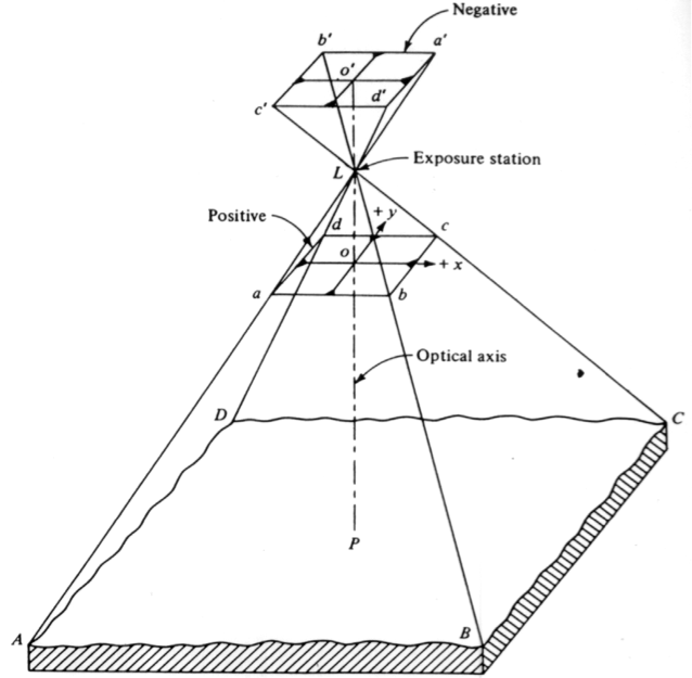
Figure 4.3 illustrates the basic geometry of a vertical photograph or image. By vertical photograph or image, we mean an image taken with a camera that is looking down at the ground. As the aircraft moves, so does the camera, and this makes it impossible to take a true vertical image. Therefore, vertical image definition allows a few degrees deviation from the nadir (the line connecting the lens frontal point and the point on the ground that is exactly beneath the aircraft). In summary, a vertical image is an image that is either looking straight down to the ground or is looking a few degrees to either side of the aircraft.
Scale of Vertical Image
As the sun's rays hit the ground, they reflect back toward the camera, and some actually enter the camera through the lens. This physical phenomenon enables us to express the ground-image relation using trigonometric principles. In Figure 4.3, ground point A is projected at image location a' and ground point B is projected at image location b' on the film. From such geometry, the film four corners a' b' c' d' cover an area on the ground represented by the square ABCD. Such relations not only enable us to compute the ground coverage of a photograph (image) but also enable us to compute the scale of such a photograph or image.
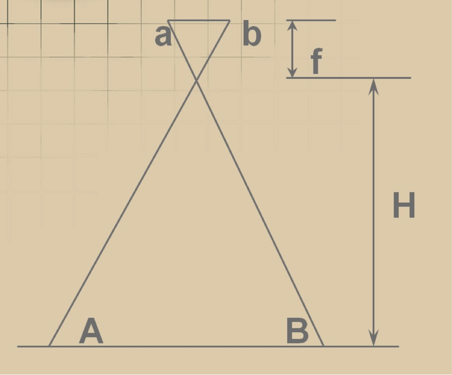
The scale of an image is the ratio of the distance on the image to the corresponding distance on the ground. In Figure 4.4, the distance on the ground AB will be projected on the image on line ab, therefore, the image scale can be computed using the following formula:
Equation 1:
Analyzing the two triangles (the small triangle with base ab and the large triangle with base AB) of Figure 4.4, one can also conclude, using the similarity of triangles principle, that the scale is also equal to:
Equation 2:
Scale is expressed either in a unitless ratio such as 1/12,000 (or 1:12,000) or in pronounced units ratio such as 1 in. = 1,000 ft (or 1”=1,000’).
Examples on Scale Computations
The following two examples will walk you step by step through the process of computing scales for imagery produced from a film-based camera and from a digital camera. In digital cameras, the scale does not play any role in defining the image quality, as is the case with film-based camera. In digital cameras, we use the Ground Sampling Distance (GSD) to describe the resolution quality of the image while in film-based cameras we use the film scale.
Scale from Film Camera
Aerial photographs were acquired from an altitude of 6,000 ft AMT (Above Mean Terrain) with a film-based aerial camera with lens focal length of 6 inches. Determine the scale of the resulting photography.
Solution:
From Figure 4.4 and equations 1 & 2,
Therefore,
OR
Scale = 1:12,000 or 1"=1,000'
Scale from Digital Camera
Scale is meaningless in digital mapping products as the scale concept was created to represent measured distances on old days maps which are plotted on paper. However, people are still using scale and it would take time before the new generation of mappers embrace the digital representation of the new geospatial products. Digital camera manufacturers provides information of the sensor used in their cameras. Some of them expresses it as 16 mega pixels which could be a square array of 6,000x6,000 pixels or a rectangular with any ratio of width/height such as 8,000x2,000 pixels or a ratio of width/height equal to 4. Some cameras manufacturers provide the sensor array size in pixels and in millimeter and some provide it with combination of number of pixels and sensor size in inch leaving wondering about the physical size of the CCD, see Figure 4.5. Figure 4.6, illustrates camera information that you need to dig deep into the provided information to obtain what you want. From Figure 4.6 which represents the information provided for the multi-spectral camera on board of the DJI Phantom 4 agricultural UAS you can indirectly derive the sensor dimensions from the given array size in pixels and the CCD size, or 3 um, which is inserted in the focal length information. The sensor dimensions in pixels were not provided directly and you would need to figure it out from the two values provided for the optical center. The optical center, or the origin of the image coordinates at 0,0, is usually located in the middle, i.e. center of the array, therefore the total width of the array is equal to 800 pixels X 2 = 1,600 pixels while the sensor height is equal to 650 pixels x 2 = 1,300 pixels. Knowing the number of pixels in the width direction, or 1,600, and the pixel size of 3 micrometer, the sensor width can be derived to be equal to 1,600 x 0.003 = 4.8 mm, similarly, the sensor height is equal to 1,300x0.003 = 3.9 mm.
The following is an example on calculating the scale for digital imagery acquired using digital camera:
Aerial imagery was acquired with a digital aerial camera with lens focal length of 100 mm and CCD size of 0.010 mm (or 10 microns). The resulting imagery had a ground resolution of 30 cm (1 ft). Determine the scale of the resulting imagery.
Solution
From Figure 4.4 and equation 1, assume that the distance ab represents the physical size of one pixel or CCD, which is 0.010 mm, and the distance AB is the ground coverage of the same pixel or 30 cm.
Therefore,
OR
Scale = 1:30,000 or 1"=2,500'
Practice Scale Computation Example:
Aerial imagery was acquired with a digital aerial camera with lens focal length of 50 mm and CCD size of 0.020 mm (or 20 microns). The resulting imagery had a ground resolution of 60 cm (2 ft). Determine the scale of the resulting imagery.
Solution
Scale = 1:30,000 or 1"=2,500'
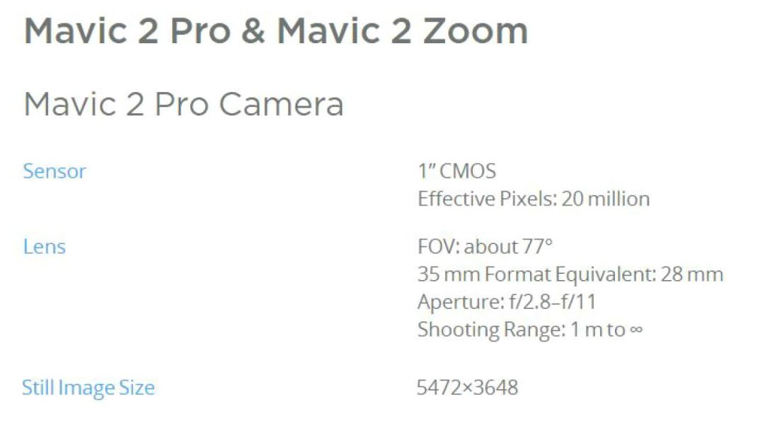
Figure 4.5 Camera information for DJI Mavic 2 Pro
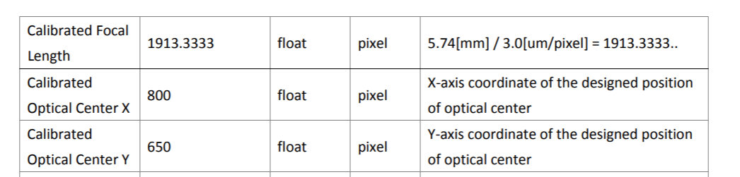
Figure 4.6 Camera information for DJI multi-spectral camera
Imagery Overlap
Imagery acquired for photogrammetric processing is flown with two types of overlap: Forward Lap and Side Lap. The following two subsections will describe each type of imagery overlap.
Forward Lap
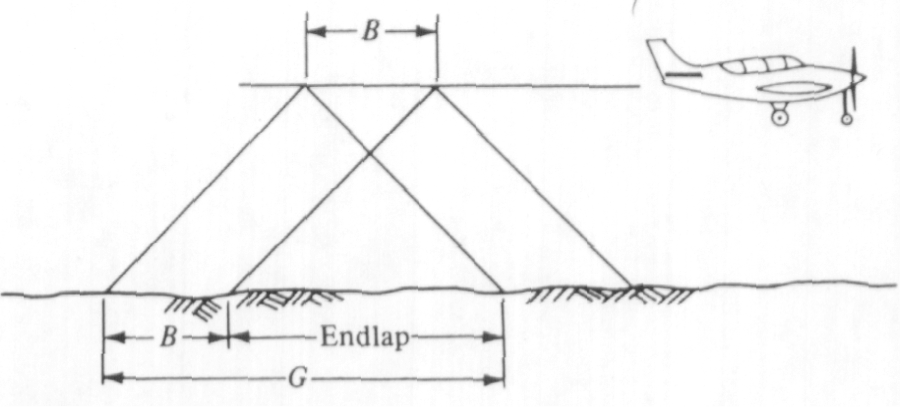
Forward lap, which is also called end lap, is a term used in photogrammetry to describe the amount of image overlap intentionally introduced between successive photos along a flight line (see Figure 4.7). Flight 3 illustrates an aircraft equipped with a mapping aerial camera taking two overlapping photographs. The centers of the two photographs are separated in the air with a distance B. Distance B is also called air base. Each photograph of Figure 4.7 covers a distance on the ground equal to G. The overlapping coverage of the two photographs on the ground is what we call forward lap.
This type of overlap is used to form stereo-pairs for stereo viewing and processing. The forward lap is measured as a percentage of the total image coverage. Typical value for the forward lap for photogrammetric work is 60%. Because of the light weight of the UAS, we expect substantial air dynamic and therefore substantial rotations of the camera (i.e., crab); therefore, I recommend the amount of forward lap to be at least 70%.
Side Lap
Side lap is a term used in photogrammetry to describe the amount of overlap between images from adjacent flight lines (see Figure 4.8). Figure 4.8 illustrates an aircraft taking two overlapping photographs from two adjacent flight lines. The distance in the air between the two flight lines (W) is called lines spacing.
This type of overlap is needed to make sure that there are no gaps in the coverage. The side lap is measured as a percentage of the total image coverage. The typical value for the side lap for photogrammetric work is 30%. However, because of the light weight of the UAS, we expect substantial air dynamic and therefore substantial rotations of the camera (i.e. crab), and therefore I recommend using at least 40% side lap.
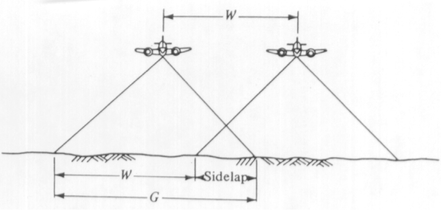
Image Ground Coverage
Ground coverage of an image is the area on the ground (the square ABCD of Figure 4.3) covered by the four corners of the photograph a'b'c'd' of Figure 4.3. Ground coverage of a photograph is determined by the camera internal geometry (focal length and the size of the CCD array) and the flying altitude above ground elevation.
Example on Image Ground Coverage:
A digital camera has an array size of 12,000 pixels by 6,000 pixels (Figure 4.9). If the physical CCD size is 0.010 mm (10 um) camera, how much area in acres will each image cover on the ground if the resulting ground resolution (GSD) of a pixel is 1 foot?
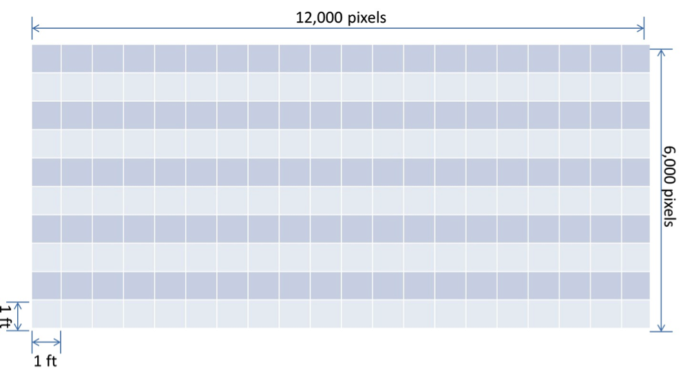
Solution
Ground coverage across the width (W) of the array = 12,000 pixels x 1 ft/pixel = 12,000 ft
Ground coverage across the height (L) of the array= 6,000 pixels x 1 ft/pixel = 6,000 ft
Covered area per image =
To Read
- Chapter 18 of Elements of Photogrammetry with Applications in GIS, 4th edition