In this section, we will discuss the topics of camera calibration and sensor boresighting.
Camera Calibration
Most existing UASs that are dedicated to photogrammetric imaging carry on board less expensive cameras that we call nonmetric cameras. Nonmetric cameras are cameras with variable interior geometry (i.e., unknown focal length) and with relatively large lens distortion. In order to conduct photogrammetric mapping from the resulting imagery from such cameras, we need to determine to a known accuracy all interior camera parameters such as the focal length and the coordinates of the principal point, and to model the lens distortion.
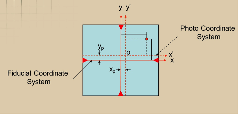
The principal point of a camera is the point where lines from opposite corners of the CCD array or the lines connecting the opposite mid-way points of the CCD array sides intersect, Figure (4.18). However, when the lens is fitted on the camera body, it is impossible to align the center of the lens and the principal point described above, resulting in offset distances xp and yp as illustrated in Figure 4.18. Those two values are determined in the process of camera calibration that needs to be represented in the photogrammetric mathematical model during computations.
Mapping film camera calibration was usually performed in special laboratories dedicated to this task such as the USGS calibration lab for film cameras, which was shut down permanently on April 1, 2017 after decades of services to the mapping community. However, with the advancements in the computational analytical model in photogrammetry, we can determine the camera parameters analytically through a process called camera self-calibration from within the aerial triangulation process. Most UAS data processing software such as the one used in this course support camera self-calibration.
Sensors Boresighting
The term “boresighting” is usually used to describe the process of determining the differences in the rotations of the sensor (such as camera) rotational axes and the rotational axes of the Inertial Measurement Unit (IMU), which is usually bolted to the camera body. The IMU is a device that contains gyros and accelerometers used in photogrammetry and lidar to sense and measure sensors rotations and accelerations. In photogrammetry where the IMU is used on an imaging camera, the boresight parameters are determined by flying over a well controlled site (site with accurate ground controls) and then conducting aerial triangulation on the resulted imagery.
The aerial triangulation process will compute the six exterior orientation parameters (X, Y, Z, omega, phi, kappa) while the IMU will measure the three orientation parameters' roll, pitch, and heading (or yaw). Comparing the two sets of the orientation angles of the camera as computed by the aerial triangulation and measured by the IMU, one can establish the differences in the rotations of the camera in reference to the inertial system (from the IMU). These differences (or offsets values) will be used to correct all the future IMU-derived orientation to convert the rotation angles from inertia to photogrammetric systems so it will be utilized in the mapping process.
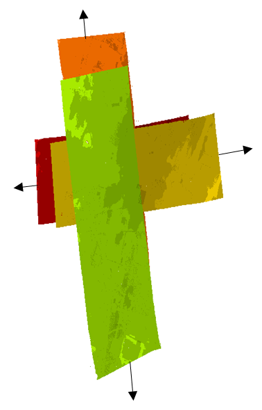
A similar process is followed for determining the offset values for the IMU used in the lidar system. For the lidar offset determination, there is no aerial triangulation used as it follows different processing steps. To determine the boresight offset values in lidar, the lidar has to be flown in a certain configuration over a well controlled site. Figure 4.19 represents an ideal design for lidar boresight determination. From the figure, there are two lines flown in the east-west directions (one flight line flown due east and the other flown the opposite direction, due west) from a certain altitude and two flight lines flown in the opposite direction (north-south) from an altitude that is nearly double the altitude of the east-west flight lines.
To Read
- Sections 3-9, 3-10, 3-11, 3-12 of Chapter 3 and section 11-12 of chapter 12 of Elements of Photogrammetry with Applications in GIS, 4th edition
- In-Situ Camera and Boresight Calibration with Lidar Data
- USGS/OSU Progress with Digital Camera in Situ Calibration Methods