Lessons
This is the course outline.
Lesson 1: Introduction to the Unmanned Aerial System
Lesson 1 Introduction
Welcome to Lesson 1! In this lesson, you will become familiar with the history behind the use of the UAS. You will also be familiar with the current status of the UAS development. In addition, you will be exposed to the different classes of UAV/UAS according to their size, weight, and missions.
At the end of this lesson, you will have a working knowledge about how the unmanned aerial missions started, the current status and the classes of the UAV/UAS.
Lesson Objectives
At the successful completion of this lesson, you should be able to:
- describe the historical evolution of the UAS;
- recognize the defense contribution to the UAS development;
- recognize the civilian contribution to the UAS development;
- understand the current state of the UAS development;
- describe the objectives beyond the use of the UAS;
- classify different UAS according to their make and characteristics;
- describe the different classes of the UAS.
Lesson Readings
- Chapter 1 of textbook 1: Bankhart et al., Introduction to the Unmanned Aircraft Systems, 2nd edition
- Chapters1 & 2 of textbook 2: Fahlstrom, et al., Introduction to UAV Systems (Aerospace Series), 4th edition
- Pacchioli, D., "Programming autonomous vehicles to fly like birds [1]"
- Chiles, J., "Drones for Hire [2]"
- Maksel, R., "Robot Reporters [3]"
- Commercial UAV News report: "6 Predictions for 2016: UAV Experts Discuss Important Developments for Commercial Drone Applications [4]"
- Parts I, II, & III of Collier Crouch, C., thesis "Integration of mini-UAVs at the tactical operations level : implications of operations, implementation, and information sharing" [5] (pdf)
- Watts, et al., Remote Sensing [6]
Lesson Activities
- Participate in the Lesson 1 Discussion Forum.
- Take the Lesson 1 Quiz (by the end of Lesson 2).
- Review the final project details [7] document.
UAS History
In this section, you will learn about the history of UAS development and its introduction to civilian and military applications.
The history of flying objects, or the unmanned aerial vehicle in its rudimentary forms, extends way back to ancient civilizations. The Chinese, around 200 AD, used paper balloons (equipped with oil lamps to heat the air) to fly over their enemies after dark, which caused fear among the enemy soldiers who believed that there was divine power involved in the flight.
In the United States, during the Civil War, both Union and Confederate forces launched balloons laden with explosives and attempted to land them in supply or ammunition depots and explode them.
As a matter of fact, the idea of unmanned aerial objects came long before manned flights. This was for the obvious reason of removing the risk of loss of life in conjunction with these experimental objects. In modern times, the idea of unmanned flying objects developed to meaning flying aerial vehicles, or aircraft, without pilots on board. Thanks to advancements in technology, the maneuvering and control of piloted flight can be sufficiently mimicked.
Names like aerial torpedo, radio-controlled vehicle, remotely piloted vehicle (RPV), remote controlled vehicle, autonomous controlled vehicle, pilotless vehicle, unmanned aerial vehicle (UAV), unmanned aircraft system (UAS), and drone are names that may be used to describe a flying object or machine without a pilot on board.
The main challenge that faced early aerospace pioneers of piloted and pilotless airplanes alike was the issue of controlling flight once the flying object was up in the air. The Wright Brothers (1903), and at about the same time, Dr. Samuel Pierpont Langley, taught the aviation world a lot about the secrets of controlled flight. Afterwards, the war machine of WWI put intense pressure on inventors and scientists to come up with innovations in all aspects of flight design including power plants, fuselage structures, lifting wing configurations and control surface arrangements. By the time WWI ended, modern day aviation had been born.
In late 1916, the US navy funded Sperry Gyroscope Company (later named Sperry Corporation) to develop an unmanned torpedo that could fly a guided distance of 1000 yards to detonate its warhead close enough to an enemy warship. Almost two years later, on March 6, 1918, after a series of failures, Sperry efforts succeeded in launching an unmanned torpedo to fly a 1000-yard course in stable guided flight. It dived onto its target at the desired time and place, and later was recovered and landed. With this successful flight, the world’s first unmanned aircraft system, which is called Curtiss N-9, was born.
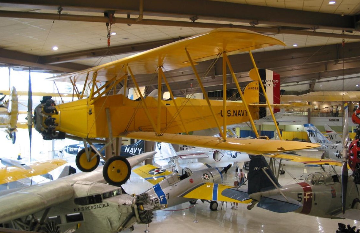
In the late 1930s, the U.S. Navy returned to the development of drones. This was highlighted by the Navy Research Lab’s development of the Curtis N2C-2 drone. (See Figure 1). The 2500-lb. bi-plane was instrumental in testing the accuracy and efficiency of the Navy anti-aircraft defense system.
World War II accelerated the development of aviation science in general and the unmanned aircraft in particular. Both the Germans and the allies successfully utilized unmanned combat aircraft. The most extensive program came about during the Vietnam War, as advances in technologies made UAVs more effective. Ryan Firebee drones by Teledyne-Ryan Aeronautical of San Diego, California were flown extensively over North Vietnam and conducted various tasks, such as reconnaissance and signals intelligence missions, leaflet drops, and surface-to-air missile radar detection.
In most recent experience, US forces used drones in the wars in Bosnia, Iraq, and Afghanistan, and drones are in continuous use in the war on terrorism around the world.
To Read
- Chapter 1 of textbook 1, Introduction to the Unmanned Aircraft Systems
- Section 1.1 and 1.2 of chapter 1 of textbook 2, Introduction to UAV Systems (Aerospace Series)
UAS System Overview
The way a pilotless aircraft is controlled determines its categorization. In general, there are three main names for pilotless aircraft:
- Unmanned Aerial Vehicle (UAV): a pilotless aircraft that is either manually controlled with a joystick or a mouse or autonomously flown by following a preprogrammed mission. The acronym UAV is the most widely used term in describing a civilian pilotless aircraft.
- Remotely Piloted Vehicle (RPV): a pilotless aircraft that is steered or controlled from a remotely located position. Manually controlled pilotless aircraft means manually controlling the aircraft position by manually adjusting its heading, altitude, and speed. In many cases, the terms UAV and RPV are interchangeably used to describe any pilotless aircraft.
- Drone: one of the oldest terms used to describe a pilotless aircraft. A drone is defined as a pilotless aircraft controlled by radio signal. Even with the emerging of the UAV and RPV names, the name “drone” is still used even for civilian pilotless aircraft. For the purpose of this course, the word drone is used to describe a pilotless aircraft equipped with a lethal payload. It is usually used by defense apparatus.
Whether it is named a UAV, an RPV, or a drone, at a minimum, the pilotless aircraft should include the following elements:
- air vehicle
- mission planning element
- command and control element
- communication link
- launch and recovery element (for some of them)
- payload
More details will be provided in Lesson 2.
To Read
- Pacchioli, D. Penn State, "Programming autonomous vehicles to fly like birds. [8]" Last modified January 15, 2014. Accessed February 4, 2014.
UAS Status
Although studying the origins of UAS development is crucial to understanding the evolution of UAV/UAS, its status in modern times is what we’re concerned with in this course.
UAV/UAS has shown sporadic appearance over time, and individual appearances have lacked momentum and continuity. It has become the pattern for UAV/UAS to serve a limited purpose and then discontinue as the purpose is satisfied. The utilization of UAS during the Vietnam War is a good example of such a sporadic rise of the use of drones. Very little was achieved surrounding the development of UAS after the war ended. This is not the case with the current period of unmanned aircrafts development.
In the last two decades, UAV technology has become very strong. This is mainly due to advancements in the fields of GPS, IMU, and electronics. Since the wars in Bosnia, Iraq and Afghanistan, the pilotless aircraft industry has witnessed increased and sizable investment that has continued to the present time.
The use of pilotless aircraft in Desert Storm in 1991, and later in Desert Shield, can be considered to be the first wide-scale deployment of UAS/UAV. During Desert Storm, some 500 UAS sorties were conducted to support intelligence gathering and to guide heavy artillery from battleships in the Persian Gulf. The success in deploying UAS in desert storm convinced militaries around the world of the usefulness of UAS in spotting enemy locations and directing artillery units.
Strong opposition to the use of UAS for defense purposes came from manned aircraft pilots and their leadership. They found a weakness in the technology that supported their claims. They built their case on the vulnerability of the data link, especially for the UAS, that relies on line-of-site based operation. However, advances in the space communications field, especially GPS, weakened their claim, as the space-based data link made the UAS no less more vulnerable than the piloted aircraft.
The United States has committed valuable resources and investments to the development of the modern UAS. NASA was immensely involved in such developments, as it is clear in the following video clip.
Four Decades of UAVs - NASA, UAV Simulation - AIAA Policy Symposium, March 2013 (4:48)
This video has clips of the following types of UAVs.
Lifting Body Remotely Piloted Vehicle (Hyper III, 1969)
Remotely Piloted Research Vehicle (Piper PA-30, 1970)
F-15 Remotely Piloted/Spin Research Vehicle (SRV, 1975)
Drones for Aerodynamic and Structural Testing (Firebee/DAST, 1977)
Highly Maneuverable Aircraft Technoloby (HiMAT, 1979)
Controlled Impact Demonstration (Boeing 720 CID, 1984)
Expendable Air-Launched Orbital Booster (Pegasus, 1990)
Spacecraft Autoland Demonstrator (Space Wedge, 1991)
Environmental Research Aircraft & Sensor Technology (Perseus, 1993)
Environmental Research Aircraft & Sensor Technology (Theseus, 1996)
Environmental Research Aircraft & Sensor Technology (Altus, 1996)
Environmental Research Aircraft & Sensor Technology (Pathfinder, 1997)
Environmental Research Aircraft & Sensor Technology (Centurion, 1998)
Environmental Research Aircraft & Sensor Technology (Helios, 2001)
High Altitude Endurance Unmanned Aerial Vehicle (Tier III, 1996)
Tailless Fighter Agility Research Aircraft (X-36, 1997)
Lifting Body Crew Return Vehicle (X-38, 1998)
Space Maneuvering Vehicle (X-40 SMV, 2000)
Inflatable Wing Technology Demonstrator (I-2000, 2001)
High Altitude Lon-Endurance Research Aircraft (Altair, 2002)
Scramjet Engine Experiment (X-42 Hyper-X, 2001)
Unmanned Combat Aerial Vehicle (X-45, 2002)
MQ-9 Predator B UAS (Ikhana, 2007)
Blended Wing Body [BWB] (X-48B, 2007)
RQ-4 Environmental Science Aircraft (Global Hawk, 2007)
UCAV Demonstrator (Phantom Ray, 2011)
Hydrogen Powered HALE (Phantom Eye, 2007)
Hybrid Wing Body [HWB] (X-48C, 2012)
The use of UAS in US Army combat operations grew from 51 operational UAS in 2001 to over 4000 in 2010. Studying the “US Army Unmanned Aircraft Systems Roadmap 2010-2035” can tell a lot about the importance of UAS in the US Army’s current and future activities. The Roadmap states that “Army UAS are the ‘Eye of the Army’ and support information dominance by providing the capability to quickly collect, process, and disseminate information to reduce the sensor-to-shooter timeline. In addition, UAS support tactical echelons in Army and joint operations and provide the warfighter a tactical advantage through near real-time situation awareness, multi-role capabilities on demand (including communications, reconnaissance, armed response, and sustainment applications), and the ability to dynamically retask.”
UAS use for daily civilian activities is no less important than it is for the armed forces. UAS are used around the world for different tasks, and most recently, for package delivery. The first video below (1:12) provides a fairly good idea about the different types and uses for the modern day UAS. UAS commercial use outside the United States is growing rapidly, as is illustrated in the second video clip. Growth in the commercial UAS market within the United States is slower than one would like to see due to tight regulations by the FAA. UAS is not allowed to be used for any commercial purposes in the United States. In a recent report, 6 Predictions for 2016: UAV Experts Discuss Important Developments for Commercial Drone Applications [4], by Jeremiah Karpowicz of the Commercial UAV News, the author discusses the latest developments in the UAS market and technologies as well as predictions on the status of UAS use for commercial applications.
"Unmanned Aerial System (UAS): Equipment and Applications" (1:12)
Video of Unmanned Aerial Systems taking off, in flight and landing. The UAS's are flying over mountains, neighborhoods, airports, roads, forestfires, lakes, oceans, and military operations. The following words appear on the screen indicating how UAS's are used: Disaster Response, Weather Monitoring, Maritime Security, Border Security, Firefighting, Drug Interdiction, Search and Rescue, and Wildlife Management.
"Drone On: The Future of UAV over the US Motherboard" (22:22)
[MUSIC PLAYING] BRIAN A. ANDERSON: Hey, it's Brian with Motherboard. I've got one word for you-- drones. Now, you've probably heard a little bit about drones in the news lately. These things fly all throughout the Middle East and the Horn of Africa. When they're not spying on suspected terrorists, they're probably killing them with Hellfire missiles.
But here's the thing. Drones are coming to the States. They're actually already here. They're being used to keep an eye on things, so they're not going to kill you, at least not yet. Motherboard has been fascinated with drones for a while now. It seems there's some misconceptions about the age of unmanned aerial vehicles.
To try and clear the air just a little bit, we're going to head out and talk to some people who are building drones, who are selling drones all over the world. With any luck, we hope to fly some drones, as well. We have absolutely no idea what we're getting into.
New York City captured by a Swiss drone hobbyist. As you're probably thinking, yes, this is illegal as all hell. And I'll be the first to say that doing this sort of thing over the site of the worst terrorist attacks on American soil? Probably not the best idea. The drone view that you've seen probably looks a bit more like this. Or more accurately, this.
The grainy, pixelated, bird's-eye views that Unmanned Aerial Vehicles, or UAVs, offer have become wildly popular on the internet. Maybe you've heard of the grim footage under its nom de YouTube, drone porn. How did we arrive at the robo wars? And where are they taking us?
To get an idea, we left our Brooklyn offices for Washington, DC, to meet up with PW Singer, one of the world's foremost experts on military robotics.
PW SINGER: We are wrestling with what it means to live, work, and even fight through a robotics revolution. The technology that we're using, with things like the Predator or the PackBot-- those are Model T 4. Those are Wright brothers equivalents. But even with that first generation, we're seeing impact on questions like, how do we catch up our laws in war, but also how do we start to catch up our laws domestically as we start to see that technology move over to the domestic side?
We're seeing an evolution that is following many other technologies. And the story of the airplane is, I think, a good illustration of where we're at and the impact of the war on an industry that becomes a game-changer. The flying machine was once thought as mere science fiction. Then the Wright brothers make it real. Within a couple years, it's utilized in war.
In World War I, at the start, they're not armed. They're just used for observation. Then they jerry-rig arm them. Then they start to specially design them to be armed. And then by the end of World War I, you see all these other roles being visualized for planes that soon move over to the commercial sector. Passenger, postal delivery, medical evacuation-- you name it.
Same exact thing is happening with robotics. First science fiction, then becomes real. The Predator was originally unarmed, just used for observation. Then they jerry-rig arm it. Then they specially design them to be armed. Now we're seeing all sorts of other roles.
BRIAN A. ANDERSON: One of the latest developments in militarized drones is autonomy-- being able to tell your drone where to go and then basically setting the thing on cruise control until it gets there is a game-changer. At the same time, drone technology is doing what most any other killer app does as it proliferates. It's becoming smaller.
We actually noticed this evolution last year when Vice was in Amman, Jordan, home to SOFEX, the world's largest military weapons expo.
SHANE SMITH: You know when you were a kid, you used to have those little model airplanes and somebody's dad would be a real nerd and have a model airplane? Now, it's all model airplane-style drones that can take pictures or drop bombs.
BRIAN A. ANDERSON: We want to check out some of these drones and size up their market, so we decided to go back.
[AIRPLANE ENGINES WHINING]
Drones are becoming hot commodities for armed forces around the world. Some 600 companies from well over 50 countries are dabbling with drone tech for both spying and killing. And nowhere is this more evident than among the trade booths at SOFEX, where we first meet this guy, a rep for a Turkish drone company.
FATIH SENKUL: My name is Fatih Senkul. I am working for Atlantis Unmanned Vehicle Solutions developing unmanned vehicles, like Aeroseeker. Some photographers want to use it for surveillance purposes, military issues, and maybe some go track-and-seek missions. Some of the military, even the Turkish Army-- what's the payload? They asked. We said, 500 grams. So let's put a very little camera and just put 500 grams of bomb and they will do a suicide attack.
That's one of the issues they offered we hadn't thought of. This is something that the military's thinking.
BRIAN A. ANDERSON: If that sounds crazy, well, then there's this.
FATIH SENKUL: I am a fan of Terminator and I love these movies, and I really would like to see some of them in the future, like 2030 maybe. So I am trying to do my best to see them, yes.
BRIAN A. ANDERSON: Unlike Fatih, I'm in no rush to hasten the rise of the machines. The next guy we meet at SOFEX maybe isn't either. Then he says something almost as crazy.
CHRIS BARTER: To me, drone means you've got something that's operational on its own. It's kind of doing its own thing, like a Hal of 2001, A Space Odyssey.
BRIAN A. ANDERSON: Here's hoping his robot, the Scout, has no intentions of becoming self-aware, like Hal, and refusing to open the pod bay doors. Now to be clear, the Scout is built by Aeryon Labs, a Canadian drone firm. Datron and its reps, like Chris, work with Aeryon on the supply side of the chain. Chris Barter is a drone dealer.
The Scout is the flagship UAV in Datron's suite of tactical robotics. Take one look at its size, and it's pretty clear that the Scout is nothing more than a surveillance system. It can fly at speeds up to 30 miles per hour. It's fully operational from negative 22 to 122 degrees Fahrenheit. And it can withstand wind gusts up to 50 miles per hour.
It's a compact, capable machine, and has been sought after by the likes of NOAA, the US Coast Guard, and FEMA.
PRESENTER 1: Is there anything that you can give me?
CHRIS BARTER: Like a hand--
PRESENTER 1: Yeah.
CHRIS BARTER: Like a brochure or something like that?
PRESENTER 1: I think we're going to hopefully be contacting you very, very soon.
CHRIS BARTER: Sounds like a plan.
BRIAN A. ANDERSON: After Chris closes the deal, he invites us back to Datron's headquarters just outside of San Diego. In addition to drones, he promises there's going to be some pretty decent surfing.
[AIRPLANE ENGINE WHINING]
CHRIS BARTER: I'm a pretty Buddhist guy. There's not much that makes me tic out there, outside of bad driving and bad surfing.
BRIAN A. ANDERSON: Would you ever use a Scout to shoot some pretty gnarly, big wave surfing footage?
CHRIS BARTER: Oh absolutely, man. That's actually one of my dreams, is to take it out to Pipeline or [INAUDIBLE].
BRIAN A. ANDERSON: So even though Chris exudes the calculating precision of a drone capitalist, he's a surfer dude at heart, and maybe even a drone hobbyist. And he isn't the only one who views drones as being a whole lot more than killers and spies. This is Justin Wellender. Notice those goggles he's putting on. Those allow for what's known as first-person viewing. So suddenly, what the drones camera sees transmits back to Justin's goggles, in effect allowing him to fly.
But we'll get back to the hobbyist later.
[MUSIC PLAYING]
Southern California has long been a hub of aerospace R&D. And today, drone firms like Datron are popping up all over the region. You can call it Drone Valley or even the Drone Zone. Datron's campus is in one of these cookie-cutter industrial parks. But soon enough we find the place and we're greeted by Chris and two of his colleagues. We'll get down to the brass tacks. Who buys a Scout?
CHRIS BARTER: I will not go into specific customers by name, but I can address customer bases that we will go after.
PRESENTER 2: The scout is man-packable, and offers fast setup, ease of use, and hot-swappable payload capabilities. The snap-together assembly requires no tools, and total assembly to takeoff time can be measured in seconds.
CHRIS BARTER: We're targeting the guy, be it the law enforcement officer, be it the squad guy who's out in a combat theater, who doesn't want to rely on some guy flying a system in Las Vegas that's being launched out of an airport that's 7,000 miles away.
BRIAN A. ANDERSON: Unlike the Scout, most so-called hunter-killer drones are flown out of Force bases throughout the American West. Many people lose sleep over the thought of these hulking drones, but many others accept the new bug-splat warfare.
CHRIS BARTER: I have no qualms when I read the news about a drone strike in Pakistan. What troubles me is that people have a tendency to kind of lump in a lot of these unmanned systems, one with another. So a Scout, which is unarmed and will probably always be unarmed, is meant specifically for surveillance, will never be harming any individual, for the most part, unless any kind of accident.
PAUL WILSON: The unit really and truly flies itself. It just waits for us to tell it when to take off, how high to go, how fast to fly, where we want it to go, and what to look at. All of our status says we're OK. We've got a GPS accuracy of 2.6 meters. So we're ready to take off. It spins up. It says, I've done all my check, so now I'm ready to take off. So I take off.
The vehicle is very good at flying itself, and it just listens to the directions of how high we want it to go, where we want it to go to, and what we want it to look at.
CHRIS BARTER: We've had a lot of interest in special use cases, like in Nome, Alaska, where they actually had an oil tanker trying to ship oil into Nome. Unfortunately, the harbor froze really early in the year. And what they actually did with the Scout was they took it off and they took photographs of the ice surrounding this harbor. And using post-processing software, they were able to actually map out the sea ice thickness so they could navigate this tanker accordingly. So it's a pretty diverse system.
BRIAN A. ANDERSON: It takes some convincing, but eventually Chris and his team let us take this diverse system of theirs for a spin. So I'm gazing up at this airborne robot, only to see it looking back down at me. I begin to feel the sting of my own privacy potentially being compromised, and I can't help but wonder if Chris and Datron feel the same.
CHRIS BARTER: Yes, we do empathize with the security and privacy rights. But we're more so focused on supporting that agency, supporting that firefighter, or supporting that law enforcement officer going into the building who needs to know either what's happening in that building, in a tactical type of situation, or what's happening on the other side. So really, it's in the court of public opinion how that gets flushed out.
BRIAN A. ANDERSON: Datron doesn't want to talk about privacy, but Chris hopes everyday civilians will come to see something like the Scout as a friend, not big brother.
CHRIS BARTER: As we deploy these into real world environments, what I hope happens is that people obtain an understanding of how these systems are actually working for them, as opposed to against them.
BRIAN A. ANDERSON: How do you think we did?
PAUL WILSON: You guys did pretty good you. Took off and you landed exactly where you wanted it to, and you didn't crash a thing. You did good.
BRIAN A. ANDERSON: No blood.
PAUL WILSON: No blood. No blood, no dents, no scratches.
BRIAN A. ANDERSON: Now that we've gotten a glimpse of the defense and professional side of this equation, we decide to check out some of the folks at the leading edge of hobby drones. A few miles down the road from Datron is 3D Robotics, a company that represents a drastic culture shift in drone tech. Alan and Sam, two engineers of the company, give us a quick run of the lab.
ALAN SANCHEZ: This is where we design all the frames, the autopilot, all the circuits, and also where we play around. So this is just where everything starts. And then the manufacturing, shipping, and testing's on the other side.
So right now, the word drone I feel has a negative connotation, especially with all the wars that have been going on, and military drones being the most common use of the word. But really, a drone is a machine that can pre-program or that has a level of autonomy that can do a job that the user can't do or doesn't want to do.
So what we're doing is turning regular RC aircraft, or even helicopters, quadcopters, into autonomous vehicles. With our autopilot, you just drop it into your existing vehicle and turn it into a fully autonomous aircraft, something that wasn't available for the masses before. And then what to do with that? That's where the user comes in. We're selling the tool, and it's up to the user to come up with a use for it. And you go buy scissors and do something bad with it, so it's basically the same thing.
CHRIS ANDERSON: I'm Chris Anderson. I'm the co-founder of 3D Robotics and I founded DIY Drones, the community that spawned us initially. This is not my day job. My day job is I'm the editor of Wired.
BRIAN A. ANDERSON: Shortly after taping this interview, Chris Anderson announced his departure from Wired to focus on 3D Robotics full-time.
CHRIS ANDERSON: Well, what you're looking at here is what we think of as something like the Apple from 1977, coming out of the Home brew Computing Club, amateurs, hobbyists, not the IBMs of the day. They're the technology in your cell phone-- the sensors, and the processors, and the wireless, et cetera. The fact that this has become cheap, and available, and ubiquitous is the enabling technology of the personal drone movement.
And we don't come out of the aerospace industry. We definitely don't come out of military. We come out of the hobbyist world, and what you're seeing here is just a bottoms-up open source community-based attempt to take a technology was once a military-industrial one and democratize it, make it available to everybody, and introduce the word personal to drone.
BRIAN A. ANDERSON: Minutes later, we're heading to a nearby field that serves as one of the main proving grounds for 3D's aircraft. Alan and Sam bring along two drones-- a small quad copter and a more traditional RC glider. We're curious to see how these guys stack up against the pro model, like the Scout.
CHRIS ANDERSON: These things are light. The planes are foam. They hit you on the head, they'll just bounce off. They won't hurt you. But they don't have weapons. They can't carry anything very heavy. They're designed basically like radio-controlled toy airplanes, but they just have a brain.
ALAN SANCHEZ: Yeah. So these things take a while to get some altitude.
PRESENTER 3: [INAUDIBLE]
Yeah.
BRIAN A. ANDERSON: And just like that, our graceful flight is cut short. The guys are spooked by a small private plane passing through our airspace, which brings us to the Federal Aviation Administration's stance on drones.
ALAN SANCHEZ: Since the FAA doesn't really have rules for what we make, we just piggyback onto RC aircraft. And so we're limited by altitude. We can only fly 400 feet or below. We have to fly within line-of-sight. Just various rules that are there that maybe we can do away with because our drones are more capable than that.
BRIAN A. ANDERSON: While 3D's quad copter and the Scout might look similar, their differences far outweigh any similarities. 3D's shoots seemingly better looking footage than the Scout that we flew, for one thing. Just compare the two. Then again, what the Scout might lack in visuals, it makes up in durability. And of course, the GPS and the slick user interface allow for reconnaissance and search-and-rescue capabilities that put it above and beyond 3D's systems, which are more or less pimped-out aircraft.
We fly 3D's drones the old-fashioned way-- with RC controllers. But thanks to 3D's autopilot, these are autonomous aircraft, meaning that just like the Scout, you can tell your DIY drone where to go, let it get there by itself, and then regain control once it's at point B. I can see how it would be easy to drop out and kick it in the Drone Zone forever, but it's time we get back to New York.
[PLANE ENGINE WHINING]
So we've made it back to Brooklyn. Before this trip, a lot of my thinking about today's drone world came with a certain alarmism. And to a degree, I think it still does, and for good reason. When you're playing with toys like these, it can be hard to forget that drone technologies are evolving in large part to be really, really good at killing a lot of people.
ALAN SANCHEZ: So if you want it to come back to you--
BRIAN A. ANDERSON: Yeah, I will.
ALAN SANCHEZ: --take this switch and pull it all the way down.
BRIAN A. ANDERSON: So I think that rigging up big Predator and Reaper drones to incinerate innocent civilians, and American citizens on foreign soil, is too much of the stuff of war crimes and extrajudicial killings. And I certainly don't sit well with the thought of a spying robot peering into my apartment window. But when it comes to some of the tactical and hobbyist drone deployments that I saw out in Jordan and San Diego, I kind of caught the bug.
It's getting harder and harder to argue against the fact that for certain scenarios, drones this makes sense. Think about Aeryon giving a couple of Scouts to Libyan rebels last year to help aid their fight against Muammar Gaddafi's forces. We all know how that story ended.
[GUNFIRE]
But beyond the war time theater, think of the myriad possibilities that drones open up for research, filmmaking, even the next generation of taco delivery. Or think about a guy like Justin, who's just really, really stoked on flying. My guess is what the domestic drone scape is going to look like in the next 5 to 10 years is about as good as yours.
But having spoken with people like Chris Barter and Sam and Alan out at 3D, I can say with relative assurity that drones are going to become more a part of our everyday lives than they already are. Should we be concerned about that? Absolutely. But so long as these drones are being put to legitimate uses, that's maybe not the worst thing, is it?
[DRONE ENGINES WHINING]
To Read
- Chiles, J. Air and Space Magazine, "Drones for Hire [2]." Last modified January 2013. Accessed February 4, 2014.
- Maksel, R. Air and Space Magazine, "Robot Reporters [3]." Last modified November 06, 2012. Accessed February 4, 2014.
- Commercial UAV News report "6 Predictions for 2016: UAV Experts Discuss Important Developments for Commercial Drone Applications [4]"
Classification of the Unmanned Aerial Systems
There is no one standard when it comes to the classification of UAS. (In this course, the terms UAS and UAV will be used interchangeably.) Defense agencies have their own standard, and civilians have their ever-evolving loose categories for UAS. People classify them by size, range and endurance, and use a tier system that is employed by the military. The US National Aviation Intelligence Integration Office [9] website provides good overview for the global UAS classification categories. For classification according to size, one can come up with the following sub-classes:
- Very small UAVs
- Micro or Nano UAVs
- Small UAVs
- Mini UAVs
- Medium UAVs
- Large UAVs
UAVs can also be classified according to the ranges they can travel and their endurance in the air, using the following subclasses developed by the US military:
- Very low cost close-range UAVs
- Close-range UAVs
- Short-range UAVs
- Mid-range UAVs
- Endurance UAVs
According to the U.S. Department of Defense, UAVs are classified into five categories, as shown in Table 1:
| Category | Size | Maximum Gross Takeoff Weight (MGTW) (lbs) | Normal Operating Altitude (ft) | Airspeed (knots) |
|---|---|---|---|---|
| Group 1 | Small | 0-20 | <1,200 AGL* | <100 |
| Group 2 | Medium | 21-55 | <3,500 | <250 |
| Group 3 | Large | <1320 | <18,000 MSL** | <250 |
| Group 4 | Larger | >1320 | <18,000 MSL | Any airspeed |
| Group 5 | Largest | >1320 | >18,000 | Any airspeed |
|
*AGL = Above Ground Level |
||||
Classification According to Size
Very small UAVs
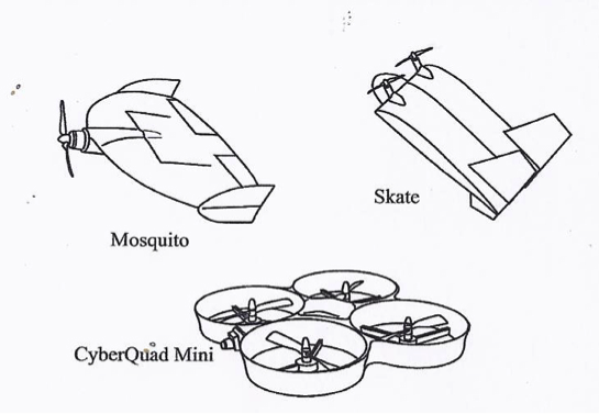
The very small UAV class applies to UAVs with dimensions ranging from the size of a large insect to 30-50 cm long. The insect-like UAVs, with flapping or rotary wings, are a popular micro design. They are extremely small in size, are very lightweight, and can be used for spying and biological warfare. Larger ones utilize conventional aircraft configuration. The choice between flapping or rotary wings is a matter of desired maneuverability. Flapping wing-based designs allow perching and landing on small surfaces. Examples of very small UAVs are the Israeli IAI Malat Mosquito (with wing span of 35 cm and endurance of 40 minutes), the US Aurora Flight Sciences Skate (with wing span of 60 cm and length of 33 cm), the Australian Cyber Technology CyberQuad Mini (with 42x42 cm square), and their latest model, CyberQuad Maxi. See Figure 1.1, below.
Small UAVs
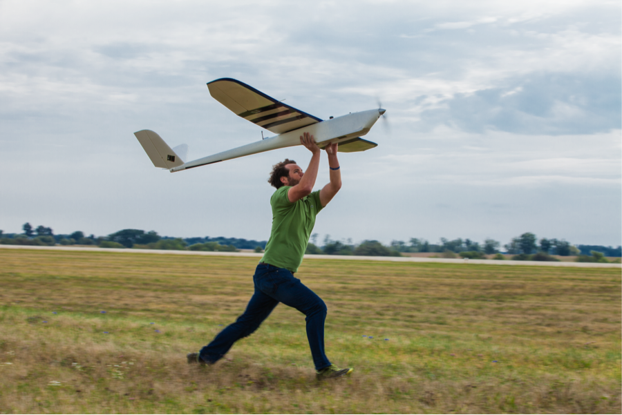
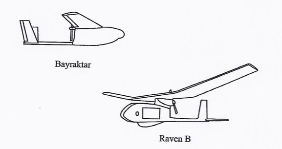
The Small UAV class (which also called sometimes mini-UAV) applies to UAVs that have at least one dimension greater than 50 cm and no larger than 2 meters. Many of the designs in this category are based on the fixed-wing model, and most are hand-launched by throwing them in the air as shown in Figure 1.2. Examples of members of this small UAV class are:
- the 1-meter long RQ-11 Raven, by US Aero Vironment with a wingspan of 1.4 m;
- the Turkish Bayraktar [13] (Figure 1.5), which weighs about 5 kg and has a data link range of 20 km;
- the US Army RQ-7 Shadow (Figure 1.3);
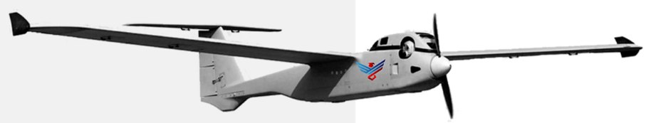
The The AiRanger™, by American Aerospace and shown in Figure 1.4. The The AiRanger™ [14] is a crossover UAV between a small and a medium-sized system
Some of the UASs of this class are based on a rotary-wing design.

Medium UAVs
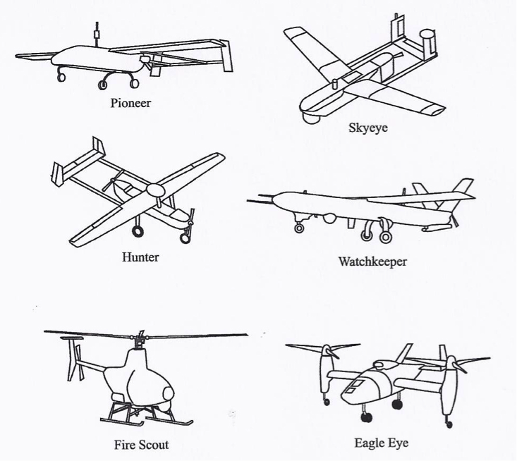
The medium UAV class applies to UAVs that are too heavy to be carried by one person but are still smaller than a light aircraft. They usually have a wingspan of about 5-10 m and can carry payloads of 100 to 200 kg. Examples of medium fixed-wing UAVs are (see Figure 1.6, below) the Israeli-US Hunter and the UK Watchkeeper. There are other brands used in the past, such as the US Boeing Eagle Eye, the RQ-2 Pioneer, the BAE systems Skyeye R4E, and the RQ-5A Hunter. The Hunter has a wingspan of 10.2 m and is 6.9 m long. It weighs about 885 kg at takeoff. The RS-20 by American Aerospace is another example of a crossover UAV that spans the specifications of a small and medium sized UAV. Many other medium UAVs can be found in the reading assignment. There are also numbers of rotary-based medium sized UAVs.
Large UAVs
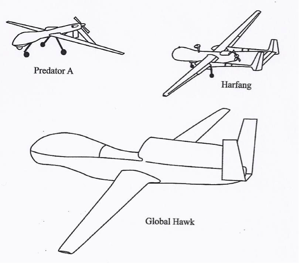
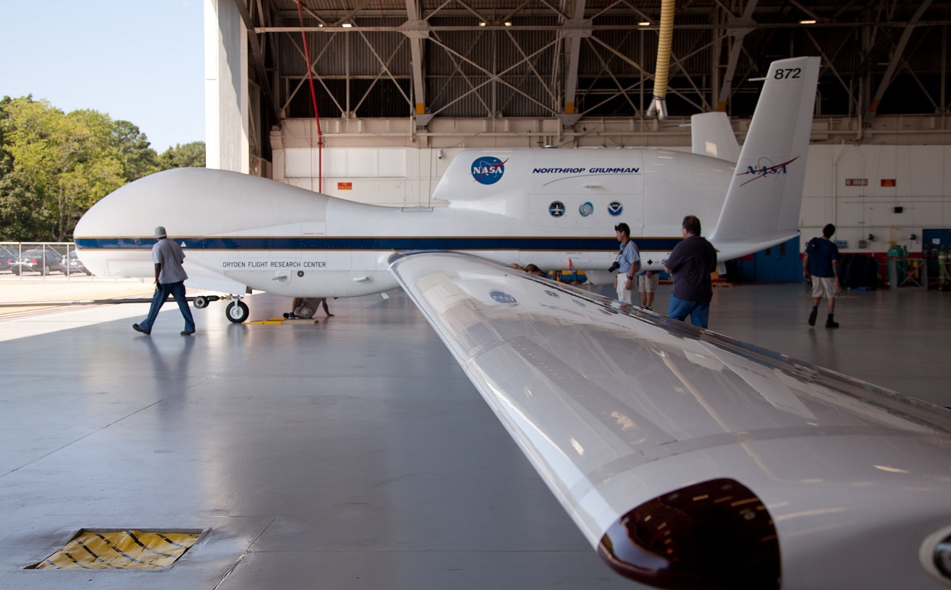
The large UAV class applies to the large UAVs used mainly for combat operations by the military. Examples of these large UAVs are the US General Atomics Predator A and B and the US Northrop Grumman Global Hawk (Figures 1.7 and 1.8).
Classification According to Range and Endurance
Very low-cost, close range UAVs
This class includes UAVs that have a range of 5 km, endurance time of 20 to 45 minutes, and cost of about $10,000 (2012 estimate). Examples of UAVs in this class are the Raven and Dragon Eye. UAVs in this class are very close to model airplanes.
Close range UAVs
This class includes UAVs that have a range of 50 km and endurance time of 1 to 6 hours. They are usually used for reconnaissance and surveillance tasks.
Short range UAVs
This class includes UAVs that have a range of 150 km or longer and endurance times of 8 to 12 hours. Like the close range UAV, they are mainly utilized for reconnaissance and surveillance purposes.
Mid-range UAVs
The mid-range class includes UAVs that have super high speed and a working radius of 650 km. They are also used for reconnaissance and surveillance purposes, in addition to gathering meteorological data.
Endurance UAVs
The endurance class includes UAVs that have an endurance of 36 hours and a working radius of 300 km. This class of UAVs can operate at altitudes of 30,000 feet. They are also used for reconnaissance and surveillance purposes.
To Read
- Chapter 2, of textbook 2, Introduction to UAV Systems (Aerospace Series)
- Crouch, C. Integration of Mini-UAVs at the Tactical Operations Level: Implications of Operations, Implementation, and Information Sharing [18]
To Do
- Read the paper “Remote Sensing [6]” by Watts, et al. Highlight agreements and differences in the UAS classifications system between the one adopted in the paper and the one given in this lesson. Post your opinion in the discussion forum for Lesson 1. Respond to at least one posting from your peers. (3 points)
Missions of the UAVs
In this section, we will discuss the different missions of the UAS.
Naming the different missions for UAVs is a difficult task, as there are so many possibilities and there have never been enough systems in use to explore all the possibilities. However, the two main classifications for UAS missions are the following:
- The military mission: Military applications focus on weapons delivery and guided missile support, as well as directing artillery and spotting enemy positions.
- The civilian mission: Civilian applications of UAS are open to the imagination, and only time will tell of the future missions of UAVs for civilian applications. As of today, civilian missions include various applications such as:
- security awareness;
- disaster response, including search and support to rescuers;
- communications and broadcast, including news/sporting event coverage;
- cargo transport;
- spectral and thermal analysis;
- critical infrastructure monitoring and inspection, including power facilities, ports, bridges, and pipelines;
- commercial photography, aerial mapping and charting, and advertising.
On the geospatial and mapping applications side, the UAS can be used for the following activities:
- aerial photography
- mapping
- LIDAR
- volumetric surveys
- digital mapping
- contour mapping
- topographic mapping
- digital terrain modeling
- aerial surveys
- photogrammetry
- temporal/spatial correlation for terrain reconstruction
- geophysical survey
Military and civilian missions of UAS overlap in many areas. They both use UAS for reconnaissance and surveillance. In addition, they both use UAS as a stationary platform over a point on the ground from which to perform many of the communications or remote sensing satellite functionalities with a fraction of the cost.
To Read
- Section 2.5 of chapter 2 of textbook 2 Introduction to UAV Systems, 4th edition
Summary and Final Tasks
Summary
We have now concluded the materials for Lesson 1, which walked us through the early history of UAS development. As is the case with most emerging modern technologies, we find the US defense program behind UAS development and its introduction to the civilian market. In addition, we learned about the different classifications for UAS. We also learned about the current status and the different applications of UAS.
One thing I would like to emphasize here is the fact that there is no single civilian owner of a large size UAS (such as the one used by the military, which is the size of a Boeing 737). In other words, there is a large gap between the size and sophistication of UAS used by the military and the ones used by civilians, which are characterized by smaller size and lesser sophistication. I believe that the reason behind this gap is strict regulation surrounding the operation of UAS in the National Airspace (NAS). Such a gap will diminish once civilian UAS has access to the NAS.
As for this lesson’s readings, try to read as much as you can through the materials available on the Internet, as it is a great resource. There is no one good textbook available so far on the subject. That is why I recommend buying, if you can, the two supplementary references listed under the course requirements in addition to the designated textbook.
(Note: Unless it is an online quiz or assignment, all deliverables should be organized and submitted in a Word document. Figures should be scanned and inserted in the document.)
Final Tasks
| 1 | Complete the Lesson 1 Quiz by the end of Lesson 2 |
|---|---|
| 2 |
Complete your participation in the discussion forum on the "Agreement and Differences in UAS Classification" detailed in Classification of the Unmanned Aerial Systems [19] by the end of Lesson 2 |
| 3 | Review the final project details in Canvas. |
Lesson 2: Unmanned Aerial System Elements
Lesson 2 Introduction
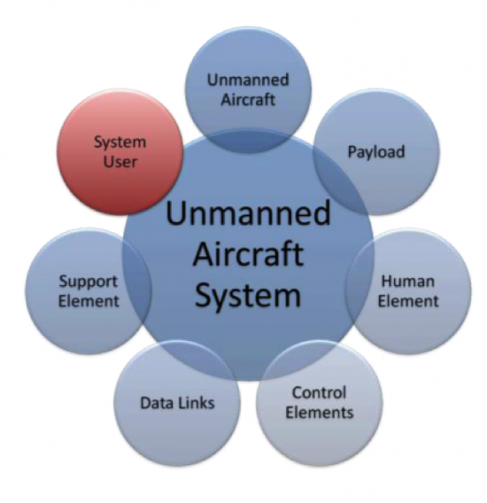
Welcome to Lesson 2! In this lesson, you will become familiar with the elements that combine to create an operational Unmanned Aerial System (UAS). Most UASs consist of an Unmanned Aerial Vehicle (UAV), human elements, payload, control elements (for a larger system it will be a ground control station (GCS) or mission planning and control station (MPCS)), and a data link communication unit (Figure 2.1). Military versions of the UAS will have an additional weapon system platform and supporting soldiers as part of the human element.
In addition, you will understand and develop knowledge about the different acquisition and auxiliary aerial sensors that are usually carried on board the UAS payload. Finally, at the end of this lesson, you will have a working knowledge of the different components forming a UAS and how the different components relate and interact with one another, the data acquisition sensors, and the auxiliary sensors that accompany a UAS mission, such as GPS and IMU.
Lesson Objectives
At the successful completion of this lesson, you should be able to:
- describe and identify the different elements of an Unmanned Aerial System (UAS);
- understand the functionality of each element making the UAS;
- explain how the different elements of a UAS complement each other;
- understand the basics in regard to an aerial vehicle design;
- describe different payloads;
- identify the different miniaturized sensors used for remote sensing;
- understand the fundamentals of digital cameras and LiDAR;
- understand the basics principals of GPS and IMU.
Lesson Readings
- Sections 3.1, 3.2, 3.3, 3.4, 3.5, and 3.6 of chapter 3 of textbook 1: Bankhart et al., Introduction to the Unmanned Aircraft Systems
- Chapter II from Crouch, C. thesis, “Integration of mini-UAVS at the tactical operations level: Implications of operations, implementation, and information sharing. [20]”
- Section 2.6 of the report "Eyes of the Army, U.S. Army Roadmap for Unmanned Aircraft Systems 2010-2035 [21]."
- Chapter 13 of textbook 2: Fahlstrom, et al., Introduction to UAV Systems (Aerospace Series)
- Chapter 9 of textbook 2: Fahlstrom, et al., Introduction to UAV Systems (Aerospace Series)
- Chao, H. et al., "Towards Low-cost Cooperative Multispectral Remote Sensing Using Small Unmanned Aircraft Systems [22]"
- Chapter 10, 11, and 12 of textbook 2: Fahlstrom, et al., Introduction to UAV Systems (Aerospace Series)
- Chapter 17 of textbook 2: Fahlstrom, et al., Introduction to UAV Systems (Aerospace Series)
- Williams, K., Human Factors Implications of Unmanned Aircraft Accidents: Flight-Control Problems [23], FAA report
- Takanmaki, I, et al., "How and why Unmanned Aircraft Vehicles can improve Real-time awareness? [24]"
Lesson Activities
- Complete the Discussion Forum for Lesson 2: SWOT Analysis
- Take the Lesson 1 and 2 quizzes
The Air Vehicle
The air vehicle is the airborne part of the system. The air vehicle here means the aircraft, in conjunction with the payload, that forms an Unmanned Aerial System (UAS). In general, the unmanned aircraft is usually called an Unmanned Aerial Vehicle (UAV) and can be either a fixed-wing or rotary airplane that flies without a human on board.
The UAV is a complicated system including structures, aerodynamic elements such as wings and control surfaces, propulsion systems, control systems, communication elements, and launch and recovery subsystems. Larger UAVs use fuel-powered engines in order to attain flight, while smaller UAVs typically use either gasoline-powered engines or electrically powered engines. When the UAV has sensors and payloads, it is customarily called an Unmanned Aerial System (UAS). In this course, the terms UAS and UAV will be used interchangeably to mean the same. Due to inclusion of the word "unmanned," there has been some resistance in recent years to use of the names Unmanned Aircraft and Unmanned Aerial Vehicle. There is a push to adopt the term Remotely Piloted Aircraft (RPA) or Remotely Piloted Vehicle (RPV) because of the crucial human involvement related to the operation of the system. UAVs come in all different sizes and shapes; however, the following are the major factors to be considered in designing a UAV:
- take-off weight
- wing span
- length
- endurance speed
- endurance time
- weight of fuel
- engine power
- engine capacity
- engine weight
- airframe weight
To Read
- Sections 3.1 and 3.2 of chapter 3 of Introduction to the Unmanned Aircraft Systems
- Chapter II from: Collier C. Crouch, 2005, “Integration of mini-UAVS at the tactical operations level: Implications of operations, implementation, and information sharing, [20]” master’s thesis, Naval postgraduate school, Monterey, California.
- Section 2.6 of the report "Eyes of the Army, U.S. Army Roadmap for Unmanned Aircraft Systems 2010-2035. [21]" It is a good reading about UAS definitions.
The Communication Data Link
The term data link is used to describe how commands are communicated back and forth between the ground control system and the autopilot. The data link is a key subsystem for any UAS, as it provides a two-way communication to ensure that missions are executed safely and according to plan. A good data link is illustrated in Figure 2.2:
- The uplink that is illustrated in Figure 2.2, below, operates with a bandwidth of a few kHz and secures sending data to control the UAS flight path and to communicate with the payload;
- The downlink from the UAS to the ground control station uses a low data rate to acknowledge commands and to send status information about the air vehicle, and uses a high data rate (1-10 Mbs) for sending payload sensor data, such as video, down to the ground control station. The downlink signal can also be used to locate and measure the position of the air vehicle (range and azimuth) in reference to the ground antenna and to improve the overall accuracy of target locations measured by the payload sensors.
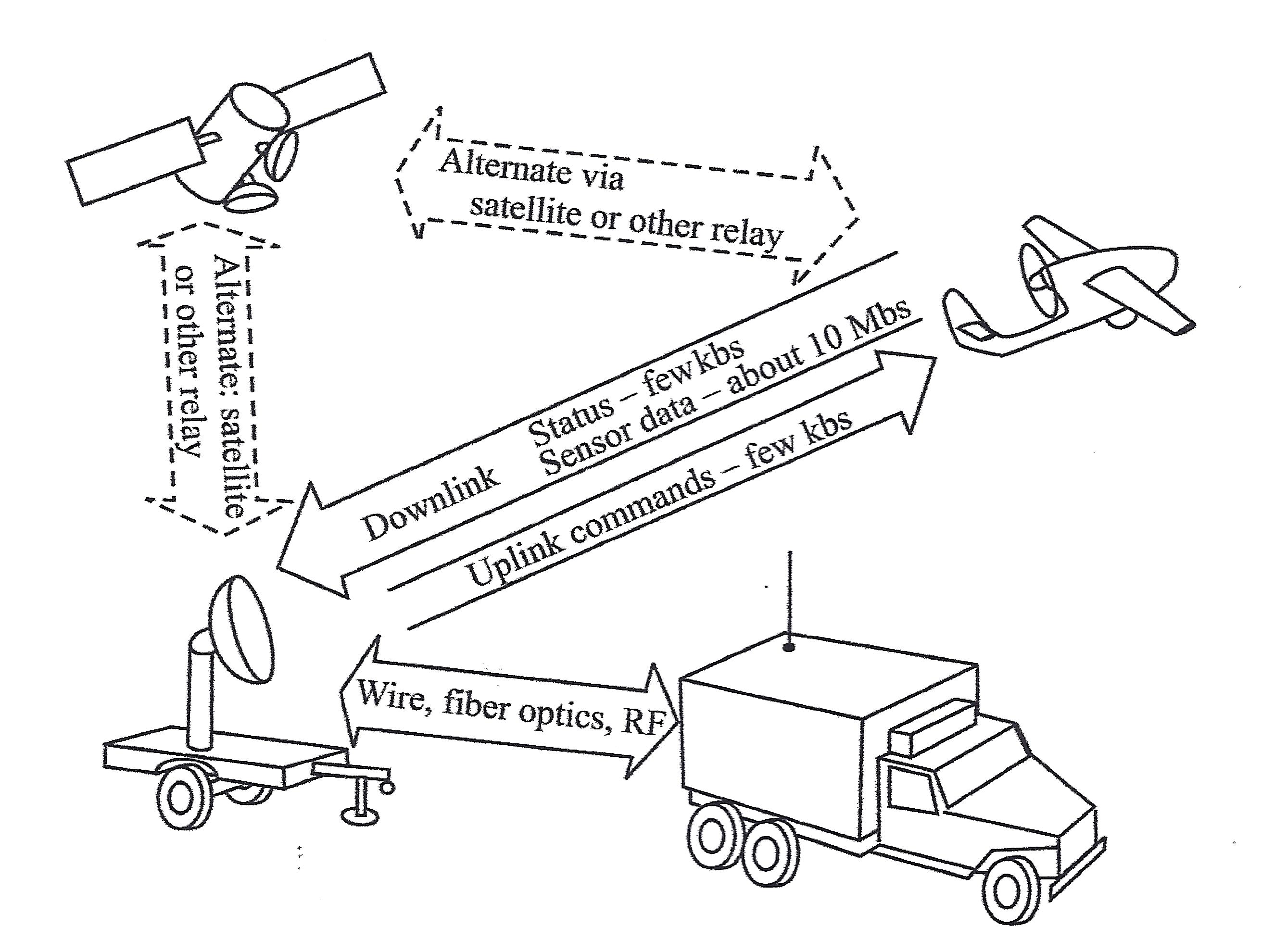
This schematic drawing illustrates the workings of a data link system. The system is composed of four elements:
- the Ground Antenna (which looks like a truck with an antenna extended from the back),
- the Ground Control Station (a satellite dish mounted on an unattached, flat-bed truck trailer),
- the UAS (airborne above the Ground System, which is the Ground Antenna and Ground Control Station together) and
- a Satellite, floating in space.
Between the Ground Antenna and the Ground Control Station is a two-way arrow containing the words "Wire, fiber optics, RF"
An arrow points from the Ground Control Station to the UAS. It contains the words "Uplink commands - few kbs"
An arrow points from the UAS to the Ground Control Station. It contains the words "Status - few kbs; Sensor data - about 10Mbs."
A two-directional arrow between the UAS and the Satellite contains the words "Alternate via satellite or other relay."
A two-directional arrow between the Ground Control Station and the Satellite contains the words "Alternate: satellite or other relay."
There are two different modes for operating a UAS. Those are:
- The radio frequency line of sight (LOS) operation, where a direct communication link is established between the UAS and the ground station, and
- The beyond line of sight (BLOS) operation. This mode of operation is used when the UAS is controlled from far distances beyond the LOS capability. Communications satellites are usually used in this mode of communication.
More details on the two operating modes will be covered in lesson 4.
To Read
- Section 3.4 of chapter 3 of textbook 1 "Introduction to the Unmanned Aircraft Systems"
- Chapter 13 of textbook 2 "Introduction to UAV Systems (Aerospace Series)"
The Command and Control Element
The command and control element is the nerve center for the UAS operation. It controls the following tasks:
- launching the vehicle,
- flying the vehicle,
- recovery of the vehicle,
- receiving and processing data from internal sensors of the flight system,
- receiving and processing data from external sensors of the payload,
- controlling the operations of the payload, and
- providing the interfaces between the UAS and the outside world.
The command and control element utilizes several subsystems to accomplish its missions. They are:
- UAV status and controls,
- payload data display and control,
- map displays for mission planning and for monitoring the flight path,
- autopilot to provide the ability for the UAV to execute its mission based on preprogrammed instructions without operator intervention,
- ground terminal for two-way communication with the UAV and the payload,
- computer(s) to:
- provide an interface between the UAV and operator,
- control the data link and the data flow between the UAV and the command and control station,
- perform the navigation functions for the system,
- perform necessary computations for the autopilot and the payload control functions,
- communication links to other organizations for command and control and for dissemination of information gathered by the UAV.
The most important parts of the command and control element are the Autopilot and the ground control station, as described in the following subsections:
Autopilot
Autopilot is the sub-system that enables partial or fully autonomous flight. A UAV can be operated completely by a remote control, where an operator steers the air vehicle all the time, or a UAV can be flown autonomously, where a pre-programmed path is fully executed from takeoff to landing by the autopilot sub-system without any pilot intervention. Small, light-weight autopilots are readily available and are made by a few manufacturers. Besides guiding the air vehicle throughout the pre-set flight path, the autopilot also executes a “lost link” routine if the UAV loses contact with the ground control station. The lost link procedure guides the UAV to a known waypoint, where contact with the ground control station can again be established. The following scenario was developed for a typical emergency procedure based on loss of link between the Yamaha RMAX UAS and the ground Control Station:
Emergency Procedures for Yamaha RMAX UAS
The RMAX utilizes a redundant communication system to ensure constant contact between the aircraft and the remote pilot. The ground control station provides real-time data regarding aircraft location, altitude and flight characteristics. The pilot constantly monitors the flight information provided to the ground control station, and through the assistance of a trained observer, maintains a visual line of sight to the aircraft. In the event of a loss of link between the aircraft and the ground control station, the subsequent procedures are followed:
- Preflight Actions - Prior to any flight, and as part of the mission preparation, the mission operator will insert appropriate lost link settings to allow the RMAX to safely return to the predetermined landing location. The settings are stored on the aircraft so that in the event of a lost link, the RMAX is able to continue operations under autonomous control.
The mission operator will identify a safe altitude and a location for the aircraft to fly to once the RMAX detects a lost link. Once the aircraft reaches the specific GPS location, it will begin at auto descent and shut off the rotors upon landing.
- In the Air - The RMAX continuously monitors the status of communication with the ground station. When the RMAX detects a loss of link with the ground station, it starts a timer. This timer value (typically 5 seconds) is set by the operator in the mission settings page. When this timer expires, the RMAX goes into lost communication mode and will command the vehicle to an operator-indicated lost communication waypoint at a predetermined altitude. The aircraft then commands a 20-second descent until touchdown. Once the aircraft lands, the aircraft automatically turns the rotors off.
| Problem: | Sign of Problem: | Monitored throughout: | Solution: |
|---|---|---|---|
| Low Signal | Vehicle is slow to respond to manual commands or PCC commands. Autopilot terminates steering mode. Audible and warning light alarms. | Yes, signal strength displayed in percentage and packet update rate. | Turn Autopilot on and abandon manual flight. Initiate auto-land. |
| Loss of Communication | Autopilot terminates manual control or fails to respond to PCC commands. Audible communication alarm and warning light. | Yes. | The vehicle returns to loss communication waypoint, hovers until elapse of flight timer, then commences auto-land procedure. |
| Loss of GPS | First indication is poor altitude hold performance, also poor position hold during hover. | Yes, indicated by the number of satellites tracked and GPS Quality PDOP. | Assume manual control of aircraft and land. |
| Low Power Avionics | Lower than nominal voltage displayed. | Yes. | Land Immediately. |
| Engine Failure | Noise level or RPM changes, engine loses power. | Yes, monitored by rotor RPM through the RPM sensor. | Return and land immediately. If the engine dies, initiate autorotation procedure. |
| Tail Rotor Failure | Loss of tail control. | No. | Switch to manual control and initiate autorotation procedure. |
Ground Control Station
The ground command station (GCS) is the site where the pilot controls the UAV during the flight. The GCS size and sophistication depends on the category of the UAS/UAV. Some large UASs require a formal facility with multiple workstations and personnel, while a GCS for small UAS can be a handheld transmitter. Most UASs used by the geospatial community are small UASs that do not require a dedicated GCS.
To Read
- Section 3.3 of chapter 3 of Introduction to the Unmanned Aircraft Systems
- Chapter 9 of the textbook Introduction to UAV Systems (Aerospace Series)
- The paper "Towards Low-cost Cooperative Multispectral Remote Sensing Using Small Unmanned Aircraft Systems [22]"
Payload
Payload refers to air vehicle (aircraft) cargo. It is also defined as the amount of cargo weight an air vehicle can safely carry. Carrying a payload on board is the sole purpose for most UASs. Payloads come in a variety of sizes, weights, and functions. In our business of geospatial remote sensing, we focus on remote sensing sensors and the necessary navigation systems accompanying them. A UAS dedicated to remote sensing and mapping missions is usually equipped with one or more of the following sensors.
Remote Sensing Sensors for the Unmanned Aerial System
- Electro Optical Sensors: such as cameras (still and video, film and digital). Aerial imaging is considered one of the most acceptable applications for UASs. Recent cameras are all digital cameras (versus film). Digital aerial cameras are categorized as follows:
- Large Format Cameras: These are mainly used on board manned aircraft and large UASs. They are very heavy for small and medium-sized UASs. Large format cameras are used to cover large areas, such as entire counties or states. Figure 2.3 illustrates a few of the most common aerial cameras used today.
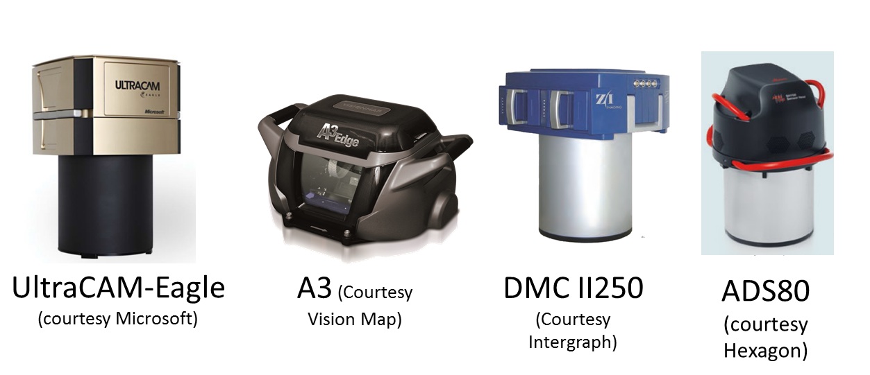 Figure 2.3 Large Format Aerial CamerasSource: (as cited by each image)
 - Medium Format Cameras (not compact): These are cameras that are smaller than large format cameras and more suitable for medium and large UASs. Cameras in this class are still too heavy for small UASs. They are widely used for manned aircraft and can be suitable for large size UASs.
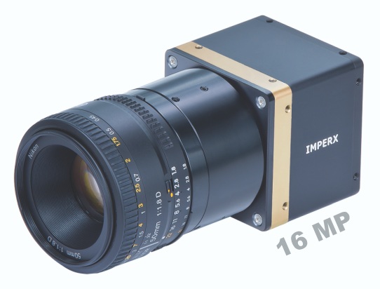
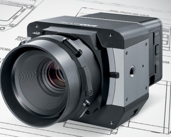
- Small and Medium Miniaturized Format Cameras: This class of cameras is similar to the cameras we own at home and use for recreational purposes, but with compacted size to be suitable for UAS use. Miniaturized cameras are the newest development in the field of digital cameras; they are developed mainly for small UASs. Examples of miniaturized cameras are the Imperx Bobcat 2 [25]camera (Figure 2.4), which has a 16 mega pixel array, weighs only 369 grams (13 ounces) and has a length of 53 mm (2 inches), and the iXA [26] camera system from Phase One Industrial (Figure 2.5). In their latest development, Phase One released their latest payload for UAS, the P3 DJI [27] which is based on mounting an iXA on DJI M300 using DJI mounting hardware and app. Here is additional information [28] about the Phase One suite of sensors for UAS.
- Large Format Cameras: These are mainly used on board manned aircraft and large UASs. They are very heavy for small and medium-sized UASs. Large format cameras are used to cover large areas, such as entire counties or states. Figure 2.3 illustrates a few of the most common aerial cameras used today.
- Infrared Sensors: An infrared sensor operates in the infrared range of the electromagnetic spectrum. Infrared sensors for remote sensing are designed to operate in two regions of the electromagnetic spectrum (EMS), those are:
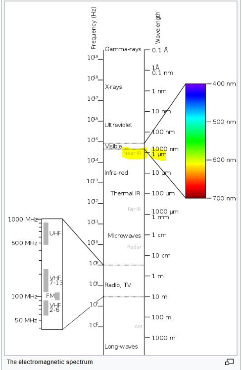
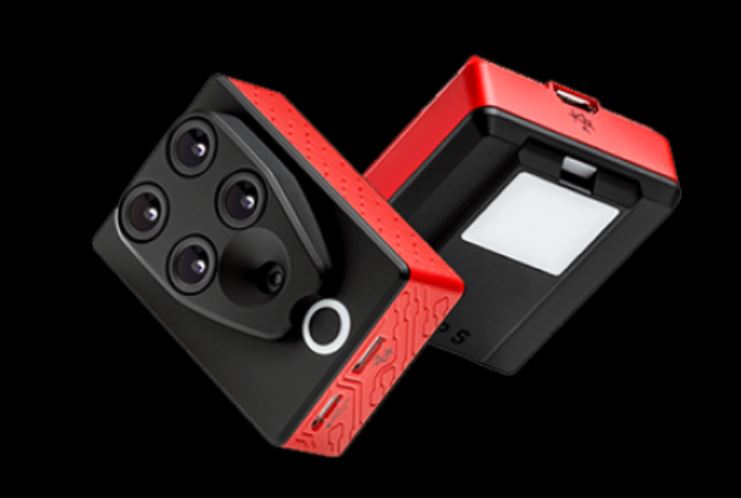
- The Near Infrared Region (NIR): NIR is barely outside the Red of the visible region of the EMS, see Figure 2.6. When the NIR band mixed with the red and green bands of the visible light, it forms a false colored infrared (CIR) image when it is displayed in the order of NIR, R, G instead of the usual R,G,B. False colored infrared imagery is effective in studying vegetation indices and vegetation health and conditions. Precision Hawks runs successful applications [31] for the precision Ag industry. Few sensors designed for UAS to provide multi-spectral imagery, including the NIR band. PARROT SEQUOIA+ [32] is one of those affordable sensors, Figure 2.7.
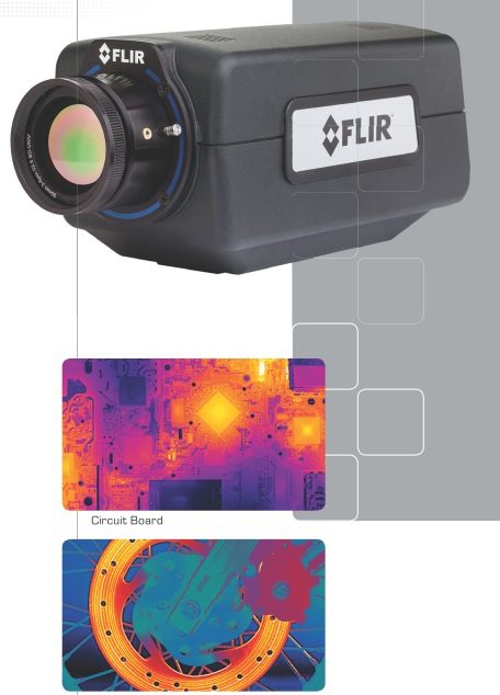
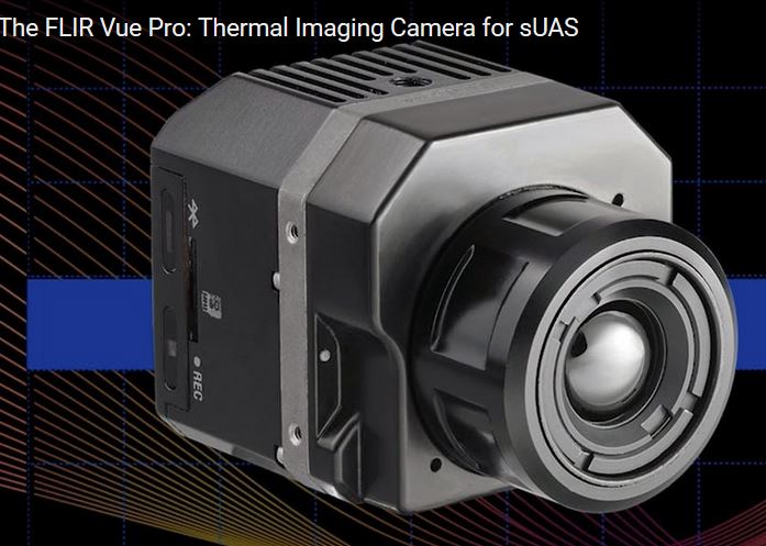
- Thermal Infrared Region (TIR): TIR sensor records the sensed heat and displays it as an image. There are two different technologies used in building such sensors. The uncooled sensor is usually less expensive and less sensitive when compared to heavyweight cooled sensors. Thermal Infrared sensors are widely used for survey and inventory of buried hot water and steam pipes and to inspect heat loss from these pipes. They are also employed for roof inspection, looking for water leaks and heat loss. An example of an infrared sensor is the FLIR A6700SC, [35] shown in Figure 2.8. Recently, FLIR offered a suite of smaller thermal infrared cameras suitable for small UAS such as the VUE PRO, Figure 2.9. In a teaming agreement with DJI, new payloads by DJI such as Zenmuse XT simultaneously carry an RGB camera and a FLIR thermal sensor.
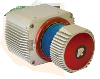
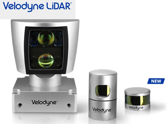
- Laser Sensors: These sensors use laser light for range finding. In addition to the laser source, LiDAR systems use GPS and Inertial Measurement Units (IMU) for precise geolocation of point cloud or terrain mapping. Laser ranging, when combined with necessary auxiliary sensors such as GPS and IMU (see details below), makes a laser-based terrain mapping system called Light Detection and Ranging (LiDAR) [37]. LiDAR systems can map the terrain generating point cloud, which can be used to precisely model the terrain below the path of the UAS. Recently, miniaturized laser-based systems started their way into UAS payloads. An example of the compact size LiDAR that is suitable for UAS is the Riegl VUX-1 [38] (Figure 2.10) and Velodyne (Figure 2.11). T o learn more about a few different UAS-based lidar systems and how people are evaluating the quality of its products, I encourage you to watch this video [39] about UAS-based lidar systems evaluation.
- SAR Sensors: Synthetic Aperture Radars are usually employed by the military for reconnaissance purposes. They require large size UASs, as they are heavy. We should not expect a civilian UAS with a SAR system as part of the payload in the foreseeable future.
Auxiliary Sensors for the Unmanned Aerial System
Auxiliary sensors here mean the navigation sensors that are necessary to determine the location and the orientation of the UAS and its remote sensors that are mentioned earlier in this section. For the UAS and onboard sensor position determination, the Global Positioning System (GPS) is used, and for the attitudes or orientation of the UAS and the onboard sensors, the Inertial Measurement Unit (IMU) is used.
Global Positioning System (GPS)
The GPS does not need introduction, as everyone is familiar with its definition. It is the same GPS that you might use to drive around town. However, GPS that is used to determine a remote sensor position usually undergoes a post-processing to enhance the accuracy of the position.
UAS are offered with two grades of GPS accuracies. The most common one is the single frequency GPS receivers as it is cheaper, and it does not require post-processing or real-time correction service. Such receivers provide location accuracy of around 1 to 2-meter. For more accurate geospatial products generation, the more accurate dual frequency receiver and precise services are need needed. The latter receivers offer two modes of operations, both of which yield positional accuracy of 1 to 3 cm with little or no ground controls required for the project. UAS vendors are fielding systems with two operational modes, those are:
- The real-time kinematic GNSS (RTK) mode: This mode of operation allows the UAS to receive in real time GPS positions corrections from GPS correction services. This mode of operation has particular requirements:
- RTK requires a GNSS base station equipped with a transmitter with a reliable link to a fairly dynamic moving platform such as UAS.
- The rover (on the UAS) itself requires a dedicated receiver for the corrections.
- The post-processed kinematic (PPK) mode: This mode of operation does not require the real time GPS positions correction, as the acquired GPS data can be post-processed at a later date. RTK operations not only require a stationary base station during the UAS mission, but the location of such base station should be surveyed and located before the UAS flies the project, something may complicate the deployment of the mission in some circumstances. Although PPK requires a base station as well, the base station’s precise location can be determined later after leaving the project area.
In principle, both RTK and PPK promise positional accuracies at the 1-3cm level. The main purpose of RTK and PPK is to minimize or eliminate the need for ground control points, thereby reducing cost. For more details on GPS, please visit GPS Defined. [42]
Inertial Measurement Unit (IMU)
An inertial measurement unit, or IMU [43], is an electronic device that measures and reports on aerial vehicle velocity, orientation, and gravitational forces using accelerometers and gyroscopes. IMUs are typically used to control and maneuver manned aircraft, unmanned aerial vehicles (UAVs), and satellites. Another important use for the IMU is that it helps IMU-enabled GPS devices to maintain positioning information when GPS-signals are unavailable, such as in tunnels, inside buildings, or when electronic interference is present.
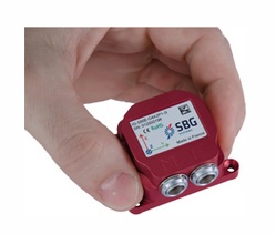
The IMU is the main component of inertial navigation systems (INS) used in aircraft, spacecraft, watercraft, and guided missiles in Geo-spatial mapping activities. The data collected from the IMUs sensors allows us to determine the orientation of the sensor, which is an important aspect in geolocating on the ground each pixel of the sensor. The IMU, like other components necessary for the operation of UASs, is miniaturized in weight and size to make it fit on small UASs. An example of these small IMUs, which are mainly designed for UASs, is the SBG 500E, [44] illustrated in Figure 2.12.
For more details on the IMU, you can visit the IMU Wikipedia page [43].
To Read
- Section 3.5 of Chapter 3 of Introduction to the Unmanned Aircraft Systems
- Chapter 10, 11, and 12 of Introduction to UAV Systems (Aerospace Series)
Launch and Recovery
The launch and recovery element is an area that requires the most human interaction. Some UASs require elaborate launching procedures, while others can be hand thrown toward the sky. Some large UASs require long runways and other field support equipment such as fuel trucks, ground power units, and ground tugs. Similarly, the requirements for recovery procedures vary widely. Most small UASs that are used for geospatial projects require simple procedures and can be hand held or launched with the use of a catapult.
Some UASs, such as target drones, are air-launched from fixed-wing aircraft. Usually, large UASs are equipped with wheels for takeoff and landing and do not need special equipment, while smaller UASs need a variety of launch and recovery strategies depending on the complexity of the system.
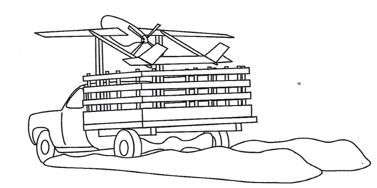
A truck driven at a speed of 60 mph can be used to launch a small UAS assuming that the launching site contains a smooth surface for the truck to use. In this type of launching method, the UAS is held in a cradle above the truck cab with its nose pointed high toward the launching path, Figure 2.13. Once speed is sufficient for takeoff, the UAS is released and lifts upward toward its takeoff path.
Many small and medium-sized UAS launch systems have a requirement to be mobile, or in other words, to be mounted on a truck or a trailer. Such mobile launchers fall within one of the following types:
- Rail Launchers: The UAS is held fast to a guide rail while it is accelerated to launch speed.
- Pneumatic Launchers: Compressed air or gas is used to provide the necessary force for launching the UAS.
- Hydraulic/Pneumatic Launchers: Compressed gaseous nitrogen is used as the power source for launch.
- Zero Length Rocket Assisted (RATO) Launching: There is no rail or track used in this mode of launching. The UAS rises directly from a holding mechanism, and it will be in free flight once the rocket is fired.
For more details on these launchers, refer to chapter 17 of the supplemental textbook Introduction to UAV Systems, 4th edition.
To Read
- Section 3.6 of Chapter 3 of Introduction to the Unmanned Aircraft Systems
- Chapter 17 of Introduction to UAV Systems (Aerospace Series)
The Human Element
Like any other technology that requires human intervention for the safety of operation, human involvement is considered to be the most important element for the successful and safe operation of the UAS. Even with autonomous flights using autopilot, the human role during launch and recovery is crucial to the operation of the UAS. As navigation technology develops further, the human role in operating a UAS will diminish dramatically.
The human element is key in almost all operational aspects of any UAS and plays a great role in the success and survival of its operation. Starting with mission planning, humans have to design and arrange a concept of operation in order to guarantee success. Equally important is the human role in the flight control process. Autopilot can do only so much without the guidance and intervention of the operator.
The role of the pilot and the observer cannot be underestimated, as without them the flight will not occur. This is true even with the most sophisticated drones, such as the Predator. Even the Predator, with sophistication and automation built in, needs a pilot to fly it. The human element is involved in all of the following aspects of operating a UAS:
- Mission planning and control: has to be performed by an operating team.
- Launch and recovery procedure: has to be performed by an operating team.
- Payload management and control: has to be managed by an operating team.
- Data links monitoring: has to be managed by an operating team.
- Ground support equipment coordination and management: has to be performed by an operating team.
Automation in operating a UAS results in less human intervention, but it will never eliminate the role of the human in such an operation. Imagine that an airline invites you to be on board an airplane flown solely by autopilot. There are no pilots on board. Would you accept such an invitation? I am certain your answer would be a big NO. Using the same analogy, could you imagine operating a UAS, which is less sophisticated than a jetliner, without a pilot and without an observer? That is how important the human role is in operating a UAS. That is at least true for the time being. Who knows what the future may bring to this field.
To Read
- Williams, K. Human Factors Implications of Unmanned Aircraft Accidents: Flight-Control Problems [23], FAA report, DOT/FAA/AM-06/8 Office of Aerospace Medicine Washington, DC 20591- April 2006
Summary and final tasks
Summary
Congratulations! You've finished most of the Lesson 2 material. What I hope you learned from this lesson is all you need to know about the different elements that form a UAS. The payload section is very valuable to individuals with background in geospatial mapping, as it goes through the different sensors utilized by the industry today. Understanding the functionality of each of the UAS elements will help you in the common lessons, where we are going to talk about Concepts of Operation (CONOP), risk assessment, and Certificate of Authorization (COA). Therefore, please make sure that you understand the different topics of this lesson and do not hesitate to ask questions.
Final Tasks
| Task | Description |
|---|---|
| 1 | Complete Lessons 1 & 2 Quizzes |
| 2 | Complete the discussion assignment on SWOT analysis in lesson 2 on CANVAS |
| 3 | Install Pix4D software. Pix4D is the data processing software you will use to process UAS imagery. Follow the instructions in Canvas. |
Lesson 3: Concept of Operation (CONOP) and Risk Assessment for UAS
Lesson 3 Introduction
Welcome to Lesson 3! In this lesson, you will become familiar with the concept of operating a UAS and how to design a Concept of Operation (CONOP). The CONOP subject focuses on the pre-flight description of the mission that a UAS operation will go through. You will also learn how to analyze risks surrounding UAS operations and to how to assess and mitigate the impact of such risks.
Lesson Objectives
At the successful completion of this lesson, you should be able to:
- understand the concept of operation design strategy;
- understand risk assessment;
- design a CONOP and Risk assessment for a UAS mission.
Lesson Readings
- Gebre-Egziabher, D., et al., "Analysis of Unmanned Aerial Vehicles Concept of Operations in ITS Applications [46]"
- FAA document “Integration of Unmanned Aircraft Systems into the National Airspace System Concept of Operations [47]”
- Read chapter 7 "Safety Assessment" of textbook 1: Barnhart, et al., Introduction to Unmanned Aircraft Systems, 2nd edition
- Lamb, G., et al., "Air Combat Command [48]"
- CONOP developed by NOAA’s National Weather Service : "River Forecast Center (RFC) Analysis and Gridded Forecast Editor Improvement [49]"
Lesson Activities
- Complete your CONOP and Risk assessment analysis as described above. Drop your completed MS Word document in the drop box in lesson 5. Watch for the actual assignment due date. (7 points)
- Complete the Lesson 3 Quiz.
- Preliminary Project Idea Milestone: submit preliminary project idea/proposal in the "Preliminary project idea" dropbox.
- Pix4D is the data processing software you will use to process UAS imagery. Install the Pix4D software using the instructions in Canvas.
- Download and practice Mission Planner Software with these instructions. [50]
- Complete your CONOP and Risk assessment analysis as detailed in the section entitled "Development of CONOP and Risk Assessment." Drop your completed MS Word document in the drop box. Watch for the actual assignment due date. (7 points)
CONOP Elements
The term CONOP means a complete description of the mission that a UAS operation goes through from launch to recovery. The CONOP includes a procedure for the mission to be carried out to achieve the mission objectives. The procedure depends on the system configuration and capabilities. UAS capabilities determined by its components such as sensors, guidance, endurance (in time), weather limitations (ceilings, wind speeds, etc.), navigation and control play key role in defining the CONOP. CONOP may also depend on other factors such as safety considerations for the UAS as well as to lives and properties along the flying path of the mission. The procedure will also include weather condition such as wind speed and visibility, as the mission may be halted or terminated if the favorable weather condition is not reached.
The FAA expectations from the provided CONOP are:
- to give FAA clear understanding of the proposed operations;
- to include:
- description of UAS;
- details of intended use;
- proposed area of operations;
- intended classes of Airspace.
- to enable or to include the development of the Operational Risk Assessment (ORA).
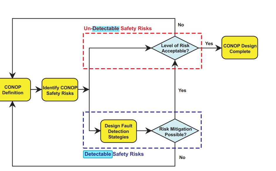
There are many ways to design CONOP one of which is described in the final report published by the ITS Research Institute of the University of Minnesota entitled “Analysis of Unmanned Aerial Vehicles Concept of Operations in ITS Applications”. In that report, the process describes the following main elements of the design:
- CONOP Definition
- Identification of CONOP Safety Risks
- Designing Fault Detection Strategies
Figure 3.1 illustrates a flow chart for small UAS concept of operation (CONOP) design process.
Many details need to be identified to complete CONOP development. Information such as:
- What are the known elements and the high-level capabilities of the system?
- What are the geographical and physical extents of the mission under execution?
- What is the time-sequence of activities that will be performed?
- What resources are needed to design, build, or retrofit the system?
- Which kind of risks are associated with different components of the system?
The block diagram in Figure 3.2 illustrates the components that make up most of the UASs available in the market today. Such a diagram is very beneficial to CONOP analysis and development, as it lists all the sub-systems included in a UAS. As you can see below, the main components that concern us in this course are the mission sensor payload, airborne data link, and navigation and control sensors. The mission sensor payload represents the highest priority for geospatial data users. Types and quality of sensors within the mission sensor payload block are directly linked to the end user's needs and expectations. The other two blocks, the airborne data link and navigation and control sensors, mainly concern the FAA and its regulations. Main FAA concerns lie in the quality of the communications and the navigational systems that steer and control the aircraft.
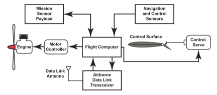
At the center of this schematic drawing is a rectangle containing the words “Flight Computer.” Arrows leave the Flight Computer from the left, the right, and from its top and bottom.
From the right, an arrow points to a smaller rectangle with rounded corners that contains the words “Motor Controller.” A subsequent arrow leaves the left side of the Motor Controller and points to a labeled drawing of the engine.
From the right of the Flight Computer, an arrow points to a smaller rectangle with rounded corners that contains the words “Control Servo.” The Control Servo is attached with a thin line to a drawing of an aircraft, which is labeled “Control Surface.”
From the bottom of the Flight Computer, an arrow points to a rectangle entitled “Airborne Data Link Tranceiver.” From the Airborne Data Link Tranceiver, an arrow points back to the Flight Computer. The Airborne Data Link Tranceiver has a small “Data Link Antenna” attached.
One arrow leaves the top of the Flight Computer. It points to a rectangle entitled “Mission Sensor Payload.” In addition, an arrow flows from the Mission Sensor Payload back to the Flight Computer.
A second arrow points to the top of the Flight Computer. This arrow originates in a rectangle labeled “Navigation and Control Sensors.”
To Read
The report "Analysis of Unmanned Aerial Vehicles Concept of Operations in ITS Applications, [46]" which discusses in detail the Concept of Operation for the UAS.
To Do
Review the FAA document “Integration of Unmanned Aircraft Systems into the National Airspace System Concept of Operations [47]”. When reading through the FAA document, focus on the components that the FAA considered when developing these Concepts of Operations. These considerations are key and beneficial to the development of your CONOP and Risk Assessment analysis that follows later in this lesson.
UAS Risk Assessment
In this section, you will explore potential risks surrounding UAS operations. The block diagram provided in section 3.1 illustrates UAS system components, each of which carries its own operational risk. In addition, there are many external risks surrounding the operational environment, such as weather and other aircraft sharing the same airspace. Review the document assigned for this section to stand on the different types of risk associated with the UAS operations.
To Read
Read chapter 7 of textbook 1 Introduction to Unmanned Aircraft Systems, 2nd edition. While you are reading through the chapter, focus on the hazard recognition and risk assessment, as you will need it for the section "Concept of Operation (CONOP) and Risk Assessment for UAS.
To Do
Review the report "Analysis of Unmanned Aerial Vehicles Concept of Operations in ITS Applications [46]" that was provided to you in the section "CONOP Elements." Focus on the discussions concerning risk assessment.
Activity: Development of CONOP and Risk Assessment
It's time to develop your own CONOP and Risk Assessment methodology for the UAS you selected for the SWOT analysis in Lesson 2, by doing the following:
- List all potential risks that surround such operation and classify them into detectable or undetectable risks.
- Select three of the risks that you identified and assess the consequences of each of these risks, if it happened, on each of the following topics:
- Project Cost (budgetary)
- Project Schedule (time)
- Safety (personnel, vehicle, facilities, etc.)
- Describe your mitigation strategy for each of these three risks, when it happens.
Your document, at minimum, should include the following sections:
- Cover page
- Table of contents
- Complete technical description of your system, element by element, with necessary illustration and images. It should include at minimum the following system items:
- UAS and its components
- Ground Control Stations
- Data link and communications frequency and protocol
- Payload (cameras, other sensors, and auxiliary systems such as GPS and IMU)
- Batteries
- Your project description and geographic site parameters. At minimum, you should include the following:
- Geo-referenced topographic map of the project area, showing project boundary
- Geo-referenced thematic map of the project area showing project boundary and surrounding features, i.e. Google map
- Sectional chart showing project boundary, airspace class, restricted flight areas, airports, towers/obstacles, etc.
- An operational plan, i.e. project plan, budget, schedule, flight plan, etc. Your flight plan should be executed in two ways:
- Manual computations according to the formulas provided in lesson 4, provide all details of computations, not just the final computed value.
- From Mission Planner software, provide screen capture and details of the flight parameters.
- Beside the details for the two flight plans design scenarios, provide at minimum the following information:
- Flying altitude
- Number of flight lines
- GSD
- Ground control points layout
- Illustration on a map showing flight lines, take off and landing spots, etc.
- Project budget should include the following cost items:
- System acquisition or lease
- Personnel travel and per diem
- Man-hours for field operations during data acquisition, including RPIC and perhaps visual observe
- Ground control points survey
- Equipment insurance
- Spare batteries and other supplies if any
- Data processing using Pix4D
- Etc.
- Identification and classification of all possible risks, classified as detectable and undetectable risks.
- Analysis of the impact of three of these risks on project cost, schedule and safety of the surroundings.
- Mitigation strategies for the three risks when it occurs.
- Summary and Conclusions.
Submit your report in a word document, NOT a pdf, to the drop box. The report should not exceed 3500 words or 15 pages (single line spacing). You will have 3 weeks to complete this assignment. (7 points or 7%)
Deadline for this assignment is at the end of lesson 5.
To Read
- Air Combat Command [48] is a good reading about UAV CONOP in general
- River Forecast Center (RFC) Analysis and Gridded Forecast Editor Improvement, [49] CONOP developed by NOAA’s National Weather Service.
To Do
- Complete your CONOP and Risk assessment analysis as described above. Drop your completed MS Word document in the drop box in Lesson 5. (7 points)
Summary and Final Tasks
Summary
Congratulations! You have finished Lesson 3, CONOP and Risk Assessment for UAS. As you may have noticed from reading the different materials provided in this lesson, the development and completion of CONOP is an important milestone that needs to be achieved for the successful operation of UASs, especially here in the United States where the FAA has strong rules and regulation against operating UASs. Without a CONOP, the operation may end up with chaotic operations and disastrous results. You also noticed that recognizing the risks surrounding a UAS operation and mitigating them not only results in a safe operation, but it will also please the FAA and encourage them to issue the required permissions to operate a UAS in the National Air Space (NAS).
Final Tasks
| 1 | Complete the Lesson 3 Quiz. |
|---|---|
| 2 | Preliminary Project Idea Milestone: Submit Preliminary project idea/proposal in the "Preliminary project idea" dropbox. |
| 3 | Pix4D is the data processing software you will use to process UAS imagery. Follow the instructions in Canvas. |
| 4 | Download and practice Mission Planner Software, following these instructions. [50] |
| 5 | Complete your CONOP and Risk assessment analysis. Submit your completed MS Word document to the drop box in Lesson 5. (7 points) |
| 6 | Participate in the discussion assignment in Canvas. |
Lesson 4: UAS Mission Planning and Control
Lesson 4 Introduction
Welcome to Lesson 4! In this lesson, you will practice planning and designing a UAS mission. For this lesson, we will focus on imaging sensor (digital cameras), as it is widely used for geospatial projects. Successful execution of any mapping project requires a tremendous amount of planning prior to mission execution. Planning must be done by an experienced person who is familiar with all aspects of mapping. Mission planning includes the following categories:
- defining products specifications;
- studying area maps;
- planning the aerial imagery;
- planning the ground controls;
- selecting procedures, personnel, and production instruments;
- estimating costs;
- developing a delivery schedule.
Lesson Objectives
At the successful completion of this lesson, you should be able to:
- understand basic requirements for mission planning;
- understand sensor internal geometry;
- describe factors affecting flight plans such as way points, product resolution and accuracy, aircraft speed, etc.;
- practice flight planning for a UAS mission;
- understand calibration requirements for imaging sensors and auxiliary systems.
Lesson Readings
- Chapter 18 of textbook 3: Wolf, et al., Elements of Photogrammetry with Applications in GIS
- Chapter 3 of textbook 3: Wolf, et al., Elements of Photogrammetry with Applications in GIS
- Sections 3-9, 3-10, 3-11, 3-12 of Chapter 3 and section 11-12 of chapter 12 of textbook 3: Wolf, et al., Elements of Photogrammetry with Applications in GIS
- Yastikli, N., et al., "In-Situ Camera and Boresight Calibration With Lidar Data [51]"
- Merchant, D., et al., "USGS/OSU Progress With Digital Camera In Situ Calibration Methods [52]"
Lesson Activities
- Complete the Lesson 4 Quiz.
- Start Pix4D processing for exercise 1 (Wiregrass Gravel Mine, Alabama) using the instructions provided to you in the last section of this lesson "Summary and Final Tasks". Submit your reports in Lesson 6. (5 points)
- Start Pix4D processing for exercise 2 (County Line Road, Dayton, Ohio) using the instructions provided to you in the last section of this lesson "Summary and Final Tasks". Submit your reports in Lesson 8. (8 points)
- Practice the use of "Mission Planner" software using the instructions provided to you in the last section of this lesson "Summary and Final Tasks" to develop a flight plan.
- Develop two flight plans for your project: one by using manual computations and formulas as described in this section, and one by using "Mission Planner" software. Compare the two.
- Participate in the "Human Elements of UAS" Discussion Forum.
Studying Area Maps
In this section, you will understand the value of studying area maps for a project prior to the development of the flight plan.
Flight planners should acquaint themselves with the project area through two types of maps before proceeding with further steps of the design; those are U.S. Topo Quadrangle Maps and Sectional Aeronautical Charts.
U.S. Topo Quadrangles Map
The U.S. Topo Quadrangles Map, mainly a topographic map, shows the details of the contours of the land (terrain elevation). See Figure 4.1. This type of map reveals all information that a planner needs about the topography in the project area. Topography affects flight plan parameters such flight lines, spacing, and imagery spacing. Quad maps can be downloaded from the USGS [53]. You can also review a sample of such maps for the State College area [54].
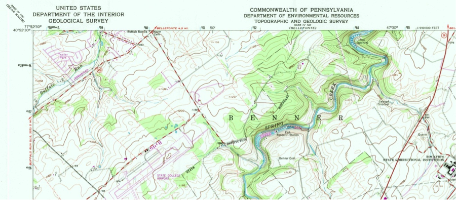
Sectional Aeronautical Chart
Sectional Aeronautical Charts, which are also called VFR charts (Figure 4.2), are described as “the primary navigational reference medium used by the VFR pilot community. The 1:500,000 scale Sectional Aeronautical Chart Series is designed for visual navigation of slow to medium speed aircraft. The topographic information featured consists of the relief and a judicious selection of visual checkpoints used for flight under visual flight rules. The checkpoints include populated places, drainage patterns, roads, railroads, and other distinctive landmarks. The aeronautical information on Sectional Charts includes visual and radio aids to navigation, airports, controlled airspace, restricted areas, obstructions, and related data. These charts are updated every six months, most Alaska Charts annually. To better understand these charts, review the FAA “Aeronautical Chart User Guide [55]”. You can also watch this YouTube video on learning how to read the sectional charts [56]:.
The VFR acronym is adopted from “Visual Flight Rules [57]” where a pilot relies on the visual see-and-avoid rule during flight. To download such charts, visit the FAA site [58].
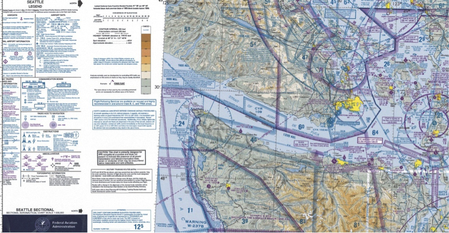
The topographic map and the aeronautical chart provide an overview of the area and the contents of the ground cover (both natural and man-made), restricted airspace such as airport approaches, high towers, etc.
Visualize FAA On Line Data and Charts
No less important than visualizing a sectional chart, is to utilize the online FAA sites and other services, which allow you to zoom in to your geographic location to stand on the airspace status and the allowed flights ceiling. Here are a couple of the free services available to the public:
1. The AirMap [60] App
2. Visualize it: See FAA UAS Data on a Map [61]
3. B4UFLY [62]
To Read
- Section 18-10 of Chapter 18 of Elements of Photogrammetry with Applications in GIS, 4th edition
Sensors Characteristics
Focal Plane and CCD Array
The focal plane of an aerial camera is the plane where all incident rays coming from the object are focused. The focal plane is where the film of a film-based camera is placed. With the introduction of digital cameras, the focal plane is occupied by the CCD array, replacing the film.
A digital camera like the ones we use at home is called a “digital frame” camera just to distinguish it from other designs of digital cameras such as “push broom” cameras. Digital frame cameras [63] have the same geometric characteristics as the film camera that employs the film as the recording medium.
A digital frame camera consists of a sensor that is a two-dimensional array of charge-coupled device [64] (CCD) elements (CCD is also called pixel). The sensor is mounted at the focal plane of the camera. When an image is taken, all CCDs of the sensor are exposed simultaneously, thus producing a digital frame. Figure 4.3 (from Wolf, page 75) illustrate how a digital camera captures an area on the ground that falls within the lens' field of view (FOV).
The size of a digital camera is measured by the size of its sensor. The higher number of CCDs (pixels) in the sensors, the bigger and more expensive the camera is. If a camera has a sensor with 4000 pixels by 4000 pixels, it is called a 16 megapixels camera. That is because it has 16,000,000 pixels. UAS imaging productivity, i.e. how many acres the UAS can cover in an hour, depends on the sensor size, battery life, and the lens focal length. The article "DJI Phantom 4 RTK vs. WingtraOne [65]" clearly illustrates the difference between UAS productivity based on sensor and UAS capabilities. In that article, you will also learn about some fundamental capabilities that we usually expect from a mapping drone.
Lens Cone
The lens for a mapping camera usually contains compound lenses put together to form the lens cone. The lens cone also contains the shutter and diaphragm.
Compound Lens
The lens is the most important and most expensive part of a mapping aerial camera. Cameras on board of the UAS are not of that level of quality, as they were not manufactured to be used as mapping cameras. Mapping cameras are called metric cameras, and are built so that the internal geometry of the camera holds its characteristics despite harsh working conditions and changing operational environments. Lenses for cameras on board of the UAS are small in size and lighter in weight. They are also less expensive than standard mapping cameras. Lenses for mapping cameras should be calibrated to determine the accurate value for focal length and lens distortion (imperfectness) characteristics.
Shutters
Shutters are used to limit the passage of light to the focal plane. The shutter speed of aerial cameras typically ranges between 1/100 and 1/1000 seconds. Shutters are of two types: focal-plane shutters or the between-the-lens shutters. The latter one is the most common shutter used for aerial cameras. Most digital camera shutters are designed according to two mechanisms: the leaf shutter (also called mechanical or global shutter or the dilating aperture shutter) or the electronic rolling shutter (curtain or sliding shutter). The leaf shutter exposes the entire sensor array at once, while the rolling shutter exposes one line of pixels at a time. For aerial imaging from a moving platform such as a UAS, leaf shutter is recommended because it minimizes image blur. To understand the shortcoming of the rolling shutter, watch this video [66].
It is important to know which shutter is used for your camera as most processing software including Pix4D provide correction for the rolling shutter effect. However, the software does not correct for it automatically, and you will need to activate that option before you start processing the imagery.
More information on different types of shutter mechanisms can be found on Wikipedia's Shutter (photography) page [67].
To Read
- Chapter 3 of Elements of Photogrammetry with Applications in GIS, 4th edition
Geometry of Vertical Image
In order to understand mission flight planning, you need to understand the geometry of the image as it is formed within the camera. The size of the CCD array and lens focal length coupled with flying altitude (above ground) determines the image scale or the ground resolution of the image. Therefore, it is essential to the work of the flight planner to have all of this information understood and available before starting to design a mission.
In photogrammetry, we usually deal with three types of imagery (photography), They are defined in term of the angle that the camera optical axis makes with the vertical (nadir), those are:
- true vertical photography: ±0º from nadir
- tilted or near-vertical photography > 0º but less than ±3º – Most used –
- oblique photography: between ±35º degree and ±55º off nadir
For the purpose of this course, we will focus only on the first two types, and that is vertical and near-vertical photography.
Figure 4.3 illustrates the basic geometry of a vertical photograph or image. By vertical photograph or image, we mean an image taken with a camera that is looking down at the ground. As the aircraft moves, so does the camera, and this makes it impossible to take a true vertical image. Therefore, vertical image definition allows a few degrees deviation from the nadir (the line connecting the lens frontal point and the point on the ground that is exactly beneath the aircraft). In summary, a vertical image is an image that is either looking straight down to the ground or is looking a few degrees to either side of the aircraft.
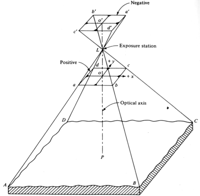
Scale of Vertical Image
As the sun's rays hit the ground, they reflect back toward the camera, and some actually enter the camera through the lens. This physical phenomenon enables us to express the ground-image relation using trigonometric principles. In Figure 4.3, ground point A is projected at image location a' and ground point B is projected at image location b' on the film. From such geometry, the film four corners a' b' c' d' cover an area on the ground represented by the square ABCD. Such relations not only enable us to compute the ground coverage of a photograph (image) but also enable us to compute the scale of such a photograph or image.
The scale of an image is the ratio of the distance on the image to the corresponding distance on the ground. In Figure 4.4, the distance on the ground AB will be projected on the image on line ab, therefore, the image scale can be computed using the following formula:
Equation 1:
Analyzing the two triangles (the small triangle with base ab and the large triangle with base AB) of Figure 4.4, one can also conclude, using the similarity of triangles principle, that the scale is also equal to:
Equation 2:
Scale is expressed either in a unitless ratio such as 1/12,000 (or 1:12,000) or in pronounced units ratio such as 1 in. = 1,000 ft (or 1”=1,000’).
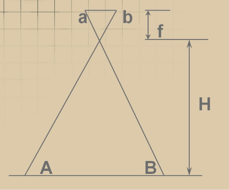
Examples on Scale Computations
The following two examples will walk you step by step through the process of computing scales for imagery produced from a film-based camera and from a digital camera. In digital cameras, the scale does not play any role in defining the image quality, as is the case with film-based camera. In digital cameras, we use the Ground Sampling Distance (GSD) to describe the resolution quality of the image while in film-based cameras we use the film scale.
Scale from Film Camera
Aerial photographs were acquired from an altitude of 6,000 ft AMT (Above Mean Terrain) with a film-based aerial camera with lens focal length of 6 inches. Determine the scale of the resulting photography.
Solution:
From Figure 4.4 and equations 1 & 2,
Therefore,
OR
Scale = 1:12,000 or 1"=1,000'
Scale from Digital Camera
Scale is meaningless in digital mapping products as the scale concept was created to represent measured distances on old days maps which are plotted on paper. However, people are still using scale and it would take time before the new generation of mappers embrace the digital representation of the new geospatial products. Digital camera manufacturers provides information of the sensor used in their cameras. Some of them expresses it as 16 mega pixels which could be a square array of 6,000x6,000 pixels or a rectangular with any ratio of width/height such as 8,000x2,000 pixels or a ratio of width/height equal to 4. Some cameras manufacturers provide the sensor array size in pixels and in millimeter and some provide it with combination of number of pixels and sensor size in inch leaving wondering about the physical size of the CCD, see Figure 4.5. Figure 4.6, illustrates camera information that you need to dig deep into the provided information to obtain what you want. From Figure 4.6 which represents the information provided for the multi-spectral camera on board of the DJI Phantom 4 agricultural UAS you can indirectly derive the sensor dimensions from the given array size in pixels and the CCD size, or 3 um, which is inserted in the focal length information. The sensor dimensions in pixels were not provided directly and you would need to figure it out from the two values provided for the optical center. The optical center, or the origin of the image coordinates at 0,0, is usually located in the middle, i.e. center of the array, therefore the total width of the array is equal to 800 pixels X 2 = 1,600 pixels while the sensor height is equal to 650 pixels x 2 = 1,300 pixels. Knowing the number of pixels in the width direction, or 1,600, and the pixel size of 3 micrometer, the sensor width can be derived to be equal to 1,600 x 0.003 = 4.8 mm, similarly, the sensor height is equal to 1,300x0.003 = 3.9 mm.
The following is an example on calculating the scale for digital imagery acquired using digital camera:
Aerial imagery was acquired with a digital aerial camera with lens focal length of 100 mm and CCD size of 0.010 mm (or 10 microns). The resulting imagery had a ground resolution of 30 cm (1 ft). Determine the scale of the resulting imagery.
Solution
From Figure 4.4 and equation 1, assume that the distance ab represents the physical size of one pixel or CCD, which is 0.010 mm, and the distance AB is the ground coverage of the same pixel or 30 cm.
Therefore,
OR
Scale = 1:30,000 or 1"=2,500'
Practice Scale Computation Example:
Aerial imagery was acquired with a digital aerial camera with lens focal length of 50 mm and CCD size of 0.020 mm (or 20 microns). The resulting imagery had a ground resolution of 60 cm (2 ft). Determine the scale of the resulting imagery.
Solution
Scale = 1:30,000 or 1"=2,500'
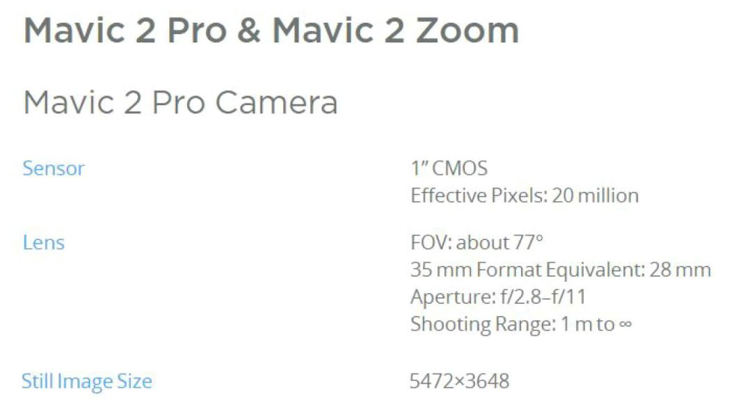
Figure 4.5 Camera information for DJI Mavic 2 Pro
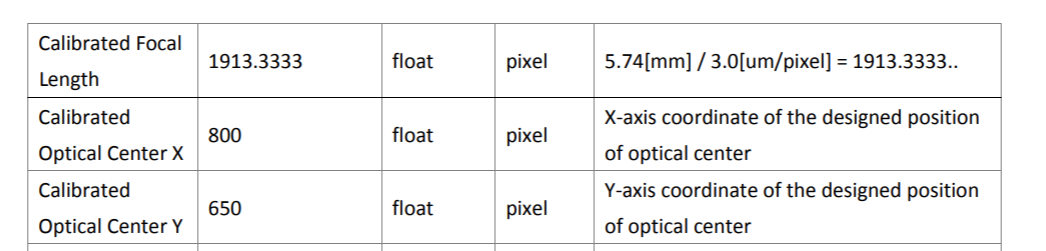
Figure 4.6 Camera information for DJI multi-spectral camera
Imagery Overlap
Imagery acquired for photogrammetric processing is flown with two types of overlap: Forward Lap and Side Lap. The following two subsections will describe each type of imagery overlap.
Forward Lap
Forward lap, which is also called end lap, is a term used in photogrammetry to describe the amount of image overlap intentionally introduced between successive photos along a flight line (see Figure 4.7). Flight 3 illustrates an aircraft equipped with a mapping aerial camera taking two overlapping photographs. The centers of the two photographs are separated in the air with a distance B. Distance B is also called air base. Each photograph of Figure 4.7 covers a distance on the ground equal to G. The overlapping coverage of the two photographs on the ground is what we call forward lap.
This type of overlap is used to form stereo-pairs for stereo viewing and processing. The forward lap is measured as a percentage of the total image coverage. Typical value for the forward lap for photogrammetric work is 60%. Because of the light weight of the UAS, we expect substantial air dynamic and therefore substantial rotations of the camera (i.e., crab); therefore, I recommend the amount of forward lap to be at least 70%.
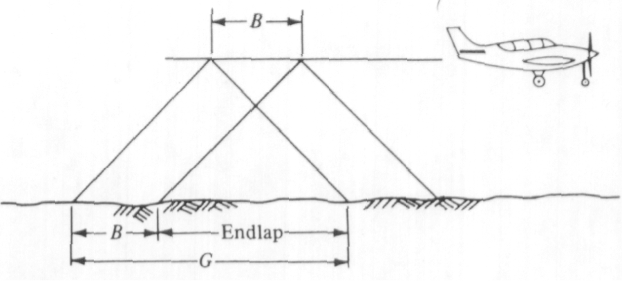
Side Lap
Side lap is a term used in photogrammetry to describe the amount of overlap between images from adjacent flight lines (see Figure 4.8). Figure 4.8 illustrates an aircraft taking two overlapping photographs from two adjacent flight lines. The distance in the air between the two flight lines (W) is called lines spacing.
This type of overlap is needed to make sure that there are no gaps in the coverage. The side lap is measured as a percentage of the total image coverage. The typical value for the side lap for photogrammetric work is 30%. However, because of the light weight of the UAS, we expect substantial air dynamic and therefore substantial rotations of the camera (i.e. crab), and therefore I recommend using at least 40% side lap.
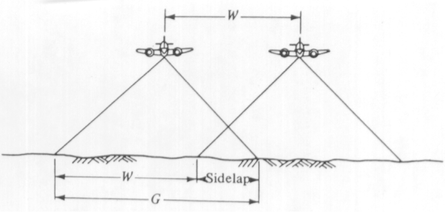
Image Ground Coverage
Ground coverage of an image is the area on the ground (the square ABCD of Figure 4.3) covered by the four corners of the photograph a'b'c'd' of Figure 4.3. Ground coverage of a photograph is determined by the camera internal geometry (focal length and the size of the CCD array) and the flying altitude above ground elevation.
Example on Image Ground Coverage:
A digital camera has an array size of 12,000 pixels by 6,000 pixels (Figure 4.9). If the physical CCD size is 0.010 mm (10 um) camera, how much area in acres will each image cover on the ground if the resulting ground resolution (GSD) of a pixel is 1 foot?
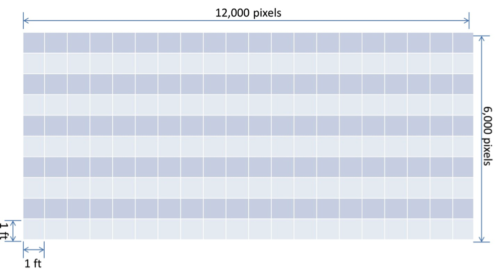
Solution
Ground coverage across the width (W) of the array = 12,000 pixels x 1 ft/pixel = 12,000 ft
Ground coverage across the height (L) of the array= 6,000 pixels x 1 ft/pixel = 6,000 ft
Covered area per image =
To Read
- Chapter 18 of Elements of Photogrammetry with Applications in GIS, 4th edition
Designing a Flight Route
In this section, we start the practical work for flight planning an imagery mission. By the end of this section, you should be able to develop a flight plan for an aerial imagery mission. Successful execution of any photogrammetric project requires thorough planning prior to the execution of any activity in the project.
The first step in the design is to decide on the scale of imagery or its resolution and the required accuracy. Once those two requirements are known, the following processes follow:
- planning the aerial photography (developing the flight plan);
- planning the ground controls;
- selecting software, instruments, and procedures necessary to produce the final products;
- cost estimation and delivery schedule.
For the flight plan, the planner needs to know the following information, some of which he or she ends up calculating:
- focal length of the camera lens;
- flying height above a stated datum or photograph scale;
- size of the CCD;
- size of CCD Array (how many pixels);
- size and shape of the area to be photographed;
- the amount of end lap and side lap;
- scale of flight map;
- ground speed of aircraft;
- other quantities as needed.
Geometry of Photogrammetric Block
Figure 4.8 shows three overlapping squares with light rays entering the camera at the lens focal point. Successive overlapping images forms a strip of imagery we usually call "strip" or "flight line," therefore photogrammetric strip (Figure 4.8) is formed from multiple overlapping images along a flight line, while photogrammetric block (Figure 4.9) consists of multiple overlapping strips (or flight lines).
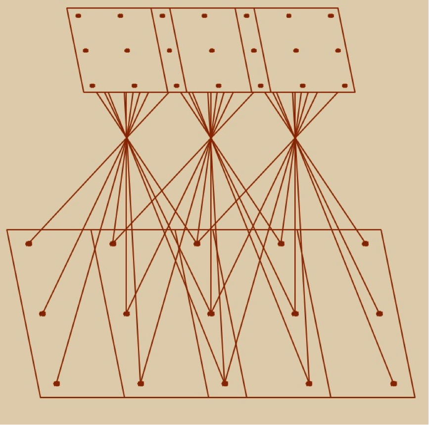
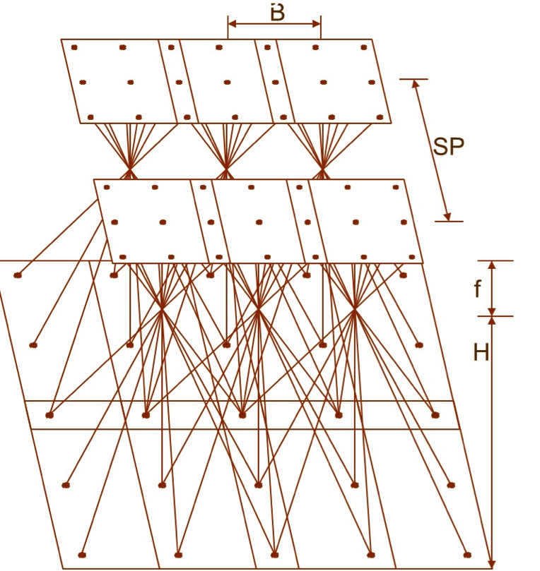
Flight Plan Design and Layout
Once we compute the ground coverage of the image, as it was discussed in the "Geometry of Vertical Image" section, we can compute the number of flight lines and the number of images and draw them on the project map (Figure 4.10), aircraft speed, flying altitude, etc.
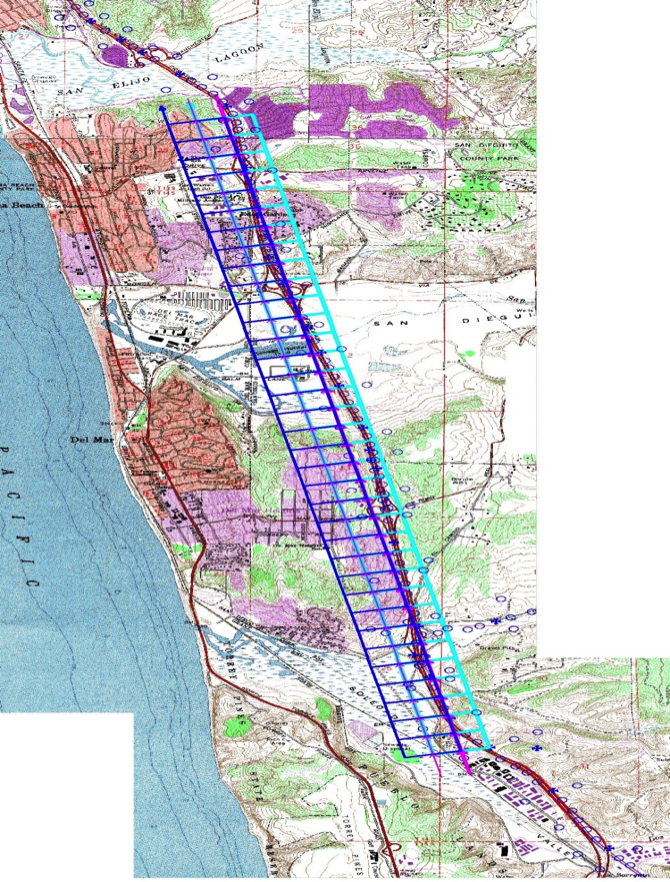
Before we start the computations of the flight lines and images numbers, I would like you to understand the following helpful hints:
- For a rectangularly shaped project, always use the smallest dimension of the project area to lay out your flight lines. This way it results in fewer flight lines and then less turns between flight lines (Figure 4.11). In Figure 4.11, the red lines with arrowheads represent flight lines or strips, while the black dash lines represent the project boundary.
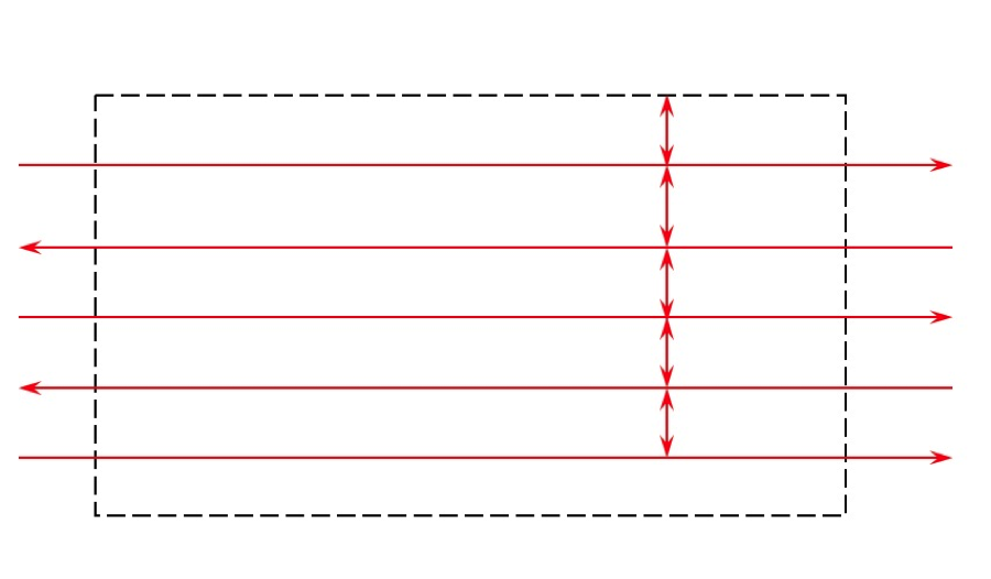 Figure 4.11 Correct flight lines orientationSource: Dr. Qassim Abdullah
 - If you have a digital camera with a rectangular shape CCD array, always choose the largest dimension of the CCD array of the camera to be perpendicular to the flight direction (Figure 4.12). In Figure 4.12, the blue rectangles represent images as taken by a camera with rectangular CCD array. The wider dimension of the array is always configured to be perpendicular to the flight direction (which is the East-West direction for this figure).
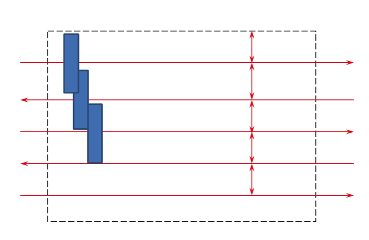 Figure 4.12 Correct camera orientationSource: Dr. Qassim Abdullah
Flight Lines Computations
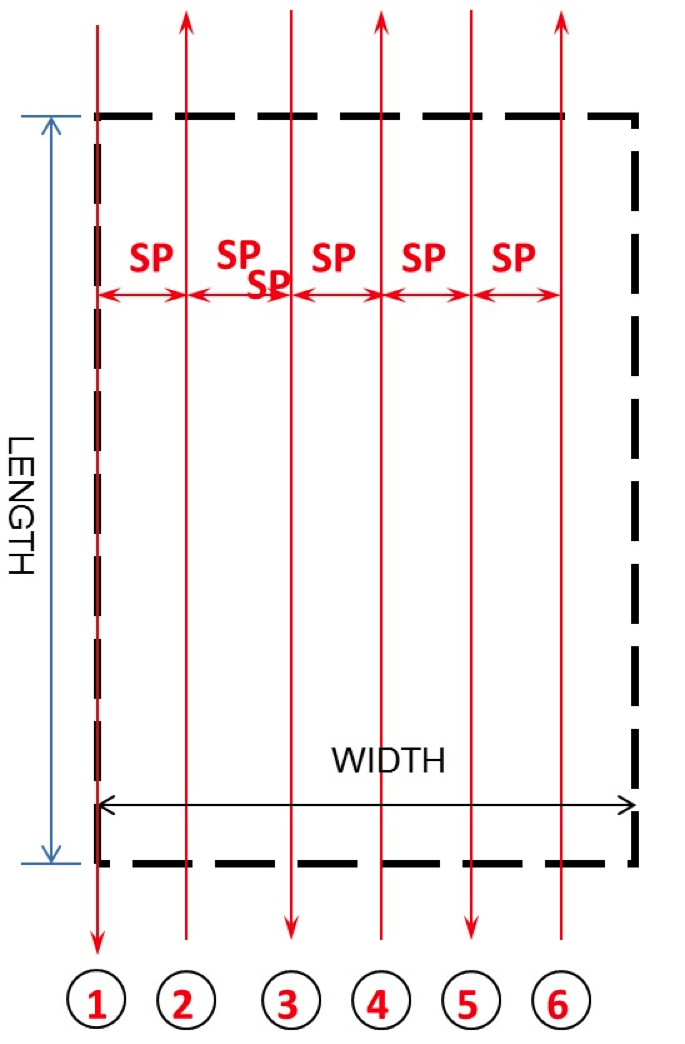
Now, let us start figuring out how many flight lines we need for the project area illustrated in Figure 4.13, to the right. Figure 4.13 shows rectangular project boundaries (in black dashed lines) with length equal LENGTH and width equal WIDTH that was designed to be flown with 6 flight lines (red lines with arrowheads). To figure out the number of flight lines needed to cover the project area, we will need to go through the following computations:
- Compute the coverage on the ground of one image (along the width of the camera CCD array (or W)) as we discussed in section 4.3.
- Compute the flight lines spacing as follows:
Line spacing or distance between flight lines (SP) = Image coverage (W) x (100 – amount of side lap)/100. - Number of flight lines (NFL) = (WIDTH / SP) + 1.
- Always round up the number of flight lines, i.e., 6.2 becomes 7.
- Start the first flight line at the east or west boundary of the project.
In Figure 4.13, you may have noticed that the flight direction for each flight line alternates between North-to-South and South-to-North from one flight line to the adjacent one. Flying the project in this manner increases the aircraft fuel efficiency so the aircraft can stay longer up in the air.
Number of Images Computations
Once we determine the number of flight lines, we need to figure out how many images will cover the project area. To do so, we need to go through the following computations:
- Compute the coverage on the ground of one image (along the height of the camera CCD array (or L)) as we discussed in section 4.3.
- Compute the distance between two consecutive images, or what we call the “airbase,” B, as follows: Airbase or distance between two consecutive images (B) = Image coverage (H) x ((100 – amount of end lap)/100).
- Number of images per flight line (NIM) = (LENGTH / B) + 1.
- Always round up the number of images, i.e., 20.2 becomes 21.
- Add two images at the beginning of the flight line before entering the project area and two images upon exiting the project area Figure 4.14 (it is needed to insure continuous stereo coverage), i.e., total of additional 4 images for each flight line, or number of images per flight line = (LENGTH / B) + 1 + 4.
- Total number of images for the project = NFL x NIM.
Figure 4.14 is the same as Figure 4.13 with added blue circles that represent photo centers of the designed images. The circles are only given to one flight line, and I will leave it to your imagination to fill all the flight lines with such circles.
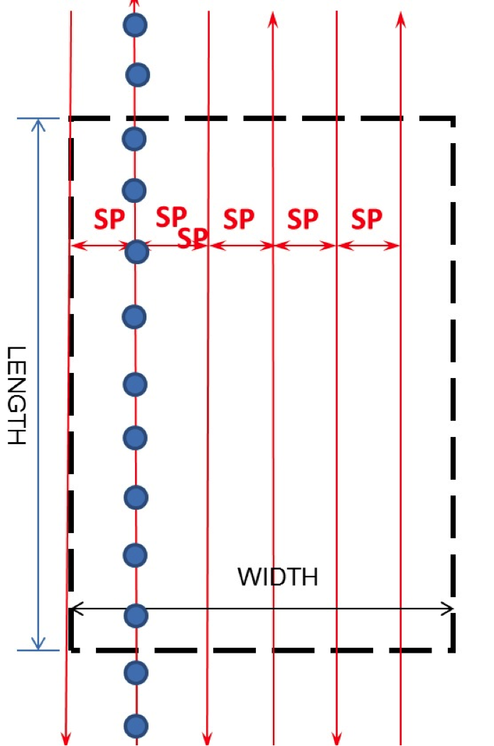
Flight Altitude Computations
Flying altitude is the altitude above certain datum the UAS flies during data acquisition. The two main datum used are either the average (mean) ground elevation or the mean sea level. Figure 4.15 illustrates the relationship between the aircraft and the datum and how the two systems relate to each other. In Figure 4.15, we have an aircraft that is flying at 3000 feet above average (mean) ground elevation, represented by the blue horizontal line in the figure. We also have the mean terrain elevation (the blue horizontal line), situated at 600 feet above the mean sea level. Therefore, the flying altitude will be expressed in two ways, those are:
- if we want to use the terrain as a reference, we will express it as Flying Altitude = 3000 feet above mean terrain or AMT;
- if we use the sea level, we will express it as Flying Altitude = 3,600 feet above mean sea level (ASL or AMSL).
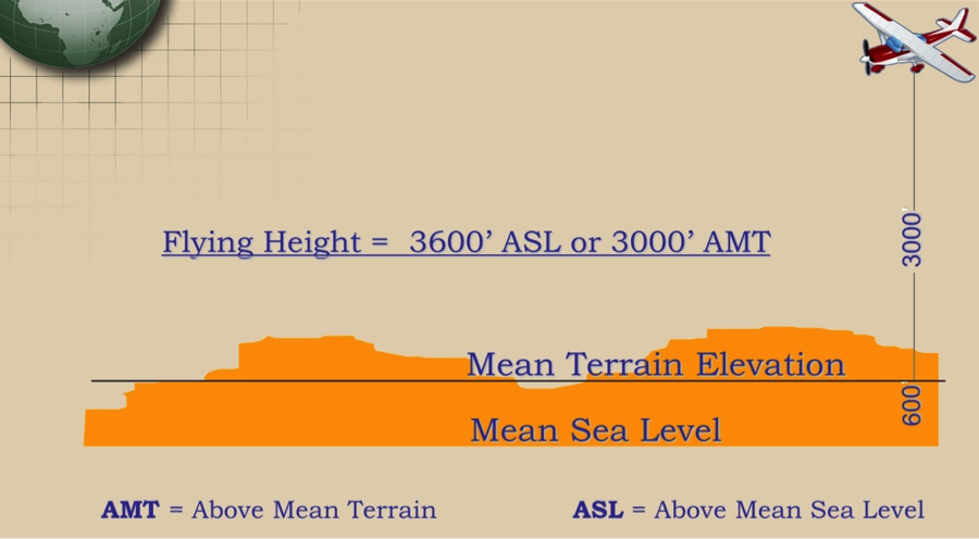
We now need to determine at what altitude the project should be flown. To do so, we go back to the camera internal geometry and scale as we discussed in section 4.3. Assume that the imagery to be acquired with a camera with lens focal length of f and with CCD size of b. We also know in advance what the imagery ground resolution or GSD should be. The flying altitude will be computed as follows:
OR
from which, H can be determined.
Here, we need to make sure that both f and b are converted to have the same linear unit, in which case the resulting altitude will be in the same linear unit of the GSD. If we assume the following values:
f = 50mm
ab = 0.010mm (or 10um)
GSD = 0.30 meter, the flying altitude will be:
meters above ground level
Aircraft Speed and Image Collection
Controlling the aircraft speed is important for maintaining the necessary forward or end lap expected for the imagery. Fly the Aircraft too fast, and you end up with less forward lap than anticipated, while flying the aircraft too slowly results in too much overlap between successive images. Both situations are harmful to the anticipated products and/or the project budget. Little amount of overlap reduces the capability of using such imagery for stereo viewing and processing, while too much overlap results in too many unnecessary images that may affect the project budget negatively. In the previous subsections, we computed the airbase or the distance between two successive images along one flight line that satisfy the amount of end lap necessary for the project. Computing the time between exposures is a simple matter once the airbase is determined and the aircraft speed is decided upon.
Computing the time between two consecutive images
When the camera exposes an image, we need the aircraft to move a distance equal to the airbase before it exposes the next image. If we assume the aircraft speed is (v) therefore the time (t) between two consecutive images is calculated from the following equation:
For example, if we computed the airbase to be 1000 ft and we used aircraft with speed of 150 knots, the time between exposure is equal to:
Way Points
In the navigation world, way points [68] are defined as “sets of coordinates that identify a point in physical space.” Close to this definition is the one used by mapping professionals, and that involves using sets of coordinates to locate the beginning point and the end point of each flight line. Way points are important for the pilot and camera operator to execute the flight plan. Way points in manned aircraft imagery acquisition are usually located a couple of miles outside the project boundary on both sides of the flight line (i.e., a couple of miles before approaching the project area and a couple of miles after exiting the project area or for UAS operations it would be a couple hundreds meters before approaching the project area and a couple hundreds meters after exiting the project area). The pilot uses way points to align the aircraft to the flight line before entering the project area. In UAS operation, a "Way Point" marks the beginning or the end of a flight line where the UAS either positions itself before starting taking pictures or it ends taking pictures on a certain flight line.
Example of Flight Plan Design and Layout
A project area is 20 miles long in the east-west directions and 13 miles in the north-south direction. The client asked for natural color (3 bands) vertical digital aerial imagery with a pixel resolution or GSD of 1 ft using a frame-based digital camera with a rectangular CCD array of 12,000 pixels across the flight direction (W) and 7,000 pixels along the flight direction (L) and a lens focal length of 100 mm. The array contains square CCDs with a dimension of 10 microns. The end lap and side lap are to be 60% and 30%, respectively. The imagery should be delivered in tiff file format with 8 bits (1 byte) per band or 24 bits per color three bands (RGB). Calculate:
- the number of flight lines necessary to cover the project area if the flight direction was parallel to the east-west boundary of the project. Assume that the first flight line falls right on the southern boundary of the project;
- the total number of digital photos (frames);
- the ground coverage of each image in acres;
- the storage requirements in gigabytes aboard the aircraft required for storing the imagery;
- the flying altitude;
- the time between two consecutive images if the aircraft speed was 150 knots.
Solution:
Looking into the project size (20x13 miles) and the one-foot GSD requirements, a mission planner should realize right away that image acquistion task for such project size and specifications can only be achieved using a manned aircraft.
The camera should be oriented so the longer dimension of the CCD array is perpendicular to the flight direction (see Figure 4.12).
- $$ \begin{array}{l}{\text { Line spacing or distance between flight lines }(\mathrm{SP})=\text { tmage coverage }(\mathrm{W}) \times(100-\text { the amount of side }} \\ {\log ) / 100}\end{array} $$ $ =12,000 \text { pixels } x 1 \mathrm{ft} / \text { pixel } \mathrm{x}(100-30) / 100)=12,000 \times 0.70=8,400 \mathrm{ft} $ $$ \begin{array}{l}{\text { Number of flight lines }(\mathrm{NFL})=(\text { project WIDTH } / \mathrm{SP})+1=((13 \text { miles } \times 5,280 \mathrm{ft} / \mathrm{mile}) / 8,400 \mathrm{ft})+1=8.171} \\ {+1=9.171 \approx 10 \text { flight lines (with rounding up). }}\end{array} $$
- $$ \begin{array}{l}{\text { Airbase or distance between two consecutive images }(\mathrm{B})=\text { Image coverage }(\mathrm{L}) \times((100-\text { amount of }} \\ {\text { end } \operatorname{lap}) / 100)=7000 \text { pixels } \times 1 \mathrm{ft} / \mathrm{pixel} \times(100-60) / 100 \mathrm{e} \text { ) }=7000 \mathrm{ft} \times 0.40=2,800 \mathrm{ft}}\end{array} $$ $$ \begin{array}{l}{\text { Number of images per flight line }=(\text { project } L E N G T H / B)+1+4=((20 \text { miles } x 5,280 \mathrm{ft} / \mathrm{mile}) / 2,800 \mathrm{ft})+} \\ {1+4=(105,600 / 2,800)+1+4=37.714+1+4=42.714 \approx 43 \text { images per flight line. }}\end{array} $$. $$ \begin{array}{l}{\text { Total number of images for the project }=10 \text { flight lines } \times 43 \text { images/fight line }=430 \text { images }} \\ {\text { (frames). }}\end{array} $$
- $$ \begin{array}{l}{\text { Ground coverage of each image }=\mathrm{W} \times \mathrm{L}=12,000 \text { pixels } \times 1 \mathrm{ft} \times 000 \text { pixels } \times 1 \mathrm{ft}=84,000,000.0 \mathrm{ft} 2=} \\ {84,000,000 \mathrm{ft} 2,143,560 \mathrm{ft} 2 / \mathrm{acre}=1,928.37 \text { acres. }}\end{array} $$
- The storage requirement for the RGB (color) images: Each pixel needs one byte per band, therefore each of the three (R,G,B) bands needs W x L x 1 byte/per pixel, or $$ 12,000 \text { pixels } \times 7,000 \text { pixels } \times 1 \text { byte/pixel }=84,000,000 \text { bytes }=84 \text { Mega bytes (Mb). } $$ $$ \begin{array}{l}{\text { Total storage requirement }=\text { Number of images } x \text { Number of bands } \times 84 \text { Mb/image }=430 \text { images } x} \\ {3 \times 84 \text { Mb/image }=108,360 \mathrm{Mb}=108.360 \text { Giga byte }(\mathrm{Gb}) .}\end{array} $$
- $ \text { Flying Altitude } H=\frac{f \times G S D}{\text { ab }}=\frac{100 \mathrm{mm} \times 1 \mathrm{ft}}{0.010 \mathrm{mm}}=10,000 \mathrm{f} \text { above terrain. } $
- Time between consectuive images $$ \begin{aligned} \text { Time }(\mathrm{t}) &=\frac{2,800 \mathrm{ft}}{150 \mathrm{knots}} \\ &=\frac{2,800 \mathrm{ft}}{150 \mathrm{knots} \cdot 1.15 \mathrm{miles} / \mathrm{hour}} \\ &=\frac{2,800 \mathrm{ft}}{172.5 \mathrm{miles} / \mathrm{hour}} \\ &=\frac{2,800 \mathrm{ft}}{172.5 \mathrm{miles} / \mathrm{hour} \cdot 5,280 \mathrm{ft} / \mathrm{mile}} \\ &=0.0030742 \mathrm{hours} \\ &=11.067 \mathrm{sec} \end{aligned} $$
Cost estimation and delivery schedule
Past experience with projects of a similar nature is essential in estimating cost and developing delivery schedule. In estimating cost, the following main categories of efforts and materials are considered:
- labor
- materials
- overhead
- profit
Once quantities are estimated as illustrated in the above steps, hours for each phase are established. Depending on the project deliverables requirements, the following labor items are considered when estimating costs:
- aerial photography
- ground control
- aerial triangulation
- stereo-plotting (# of models = # photos -1)
- map editing
- ortho production
- lidar data cleaning
The table in Figure 4.16 provides an idea about the going market rates for geospatial products that can be used as guidelines when pricing a mapping project using manned aircraft operation and metric digital camera and lidar. The industry needs to come up with a comparable table based on Unmanned operations. There is no good pricing model established for UAS operation as the standards and produicts quality are widely varialble depending on who offers such services and whether it fall strictly under the "Professional Services" designation.
| Product | GSD ft | Price per sq mile | Comments |
|---|---|---|---|
| Ortho | 0.5 | $150-$200 | Based on large projects |
| Ortho | 1.0 | $80-$100 | Based on large projects |
| Ortho | 2.0 | $30-$60 | Based on large projects |
| lidar | 3.2 | $100-$500 | Depends on accuracy, terrain, and required details |
Delivery Schedule
After the project hours are estimated, each phase of the project may be scheduled based on the following:
- number of instruments or workstations available
- number of trained personnel available
- amount of other work in progress and its status
- urgency of the project to the client
The schedule will also consider the constrains on the window of opportunity due to weather conditions. Figure 4.17 illustrates the number of days, per state/region, available annually for aerial imaging campaigns. Areas like the state of Maine have only 30 cloudless days per year that are suitable for aerial imaging activities.
To Read
Chapter 18 of Elements of Photogrammetry with Applications in GIS, 4th edition
To Do
For practice, develop two flight plans for your project, one by using manual computations and formulas as described in this section and one by using "Mission Planner" software. Compare the two.
Sensors Calibration and Boresighting
In this section, we will discuss the topics of camera calibration and sensor boresighting.
Camera Calibration
Most existing UASs that are dedicated to photogrammetric imaging carry on board less expensive cameras that we call nonmetric cameras. Nonmetric cameras are cameras with variable interior geometry (i.e., unknown focal length) and with relatively large lens distortion. In order to conduct photogrammetric mapping from the resulting imagery from such cameras, we need to determine to a known accuracy all interior camera parameters such as the focal length and the coordinates of the principal point, and to model the lens distortion.
The principal point of a camera is the point where lines from opposite corners of the CCD array or the lines connecting the opposite mid-way points of the CCD array sides intersect, Figure (4.18). However, when the lens is fitted on the camera body, it is impossible to align the center of the lens and the principal point described above, resulting in offset distances xp and yp as illustrated in Figure 4.18. Those two values are determined in the process of camera calibration that needs to be represented in the photogrammetric mathematical model during computations.
Mapping film camera calibration was usually performed in special laboratories dedicated to this task such as the USGS calibration lab for film cameras, which was shut down permanently on April 1, 2017 after decades of services to the mapping community. However, with the advancements in the computational analytical model in photogrammetry, we can determine the camera parameters analytically through a process called camera self-calibration from within the aerial triangulation process. Most UAS data processing software such as the one used in this course support camera self-calibration.
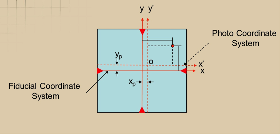
Sensors Boresighting
The term “boresighting” is usually used to describe the process of determining the differences in the rotations of the sensor (such as camera) rotational axes and the rotational axes of the Inertial Measurement Unit (IMU), which is usually bolted to the camera body. The IMU [43] is a device that contains gyros and accelerometers used in photogrammetry and lidar to sense and measure sensors rotations and accelerations. In photogrammetry where the IMU is used on an imaging camera, the boresight parameters are determined by flying over a well controlled site (site with accurate ground controls) and then conducting aerial triangulation on the resulted imagery.
The aerial triangulation process will compute the six exterior orientation parameters (X, Y, Z, omega, phi, kappa) while the IMU will measure the three orientation parameters' roll, pitch, and heading (or yaw). Comparing the two sets of the orientation angles of the camera as computed by the aerial triangulation and measured by the IMU, one can establish the differences in the rotations of the camera in reference to the inertial system (from the IMU). These differences (or offsets values) will be used to correct all the future IMU-derived orientation to convert the rotation angles from inertia to photogrammetric systems so it will be utilized in the mapping process.
A similar process is followed for determining the offset values for the IMU used in the lidar system. For the lidar offset determination, there is no aerial triangulation used as it follows different processing steps. To determine the boresight offset values in lidar, the lidar has to be flown in a certain configuration over a well controlled site. Figure 4.19 represents an ideal design for lidar boresight determination. From the figure, there are two lines flown in the east-west directions (one flight line flown due east and the other flown the opposite direction, due west) from a certain altitude and two flight lines flown in the opposite direction (north-south) from an altitude that is nearly double the altitude of the east-west flight lines.
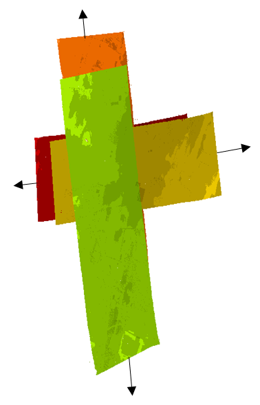
To Read
- Sections 3-9, 3-10, 3-11, 3-12 of Chapter 3 and section 11-12 of chapter 12 of Elements of Photogrammetry with Applications in GIS, 4th edition
- In-Situ Camera and Boresight Calibration with Lidar Data [51]
- USGS/OSU Progress with Digital Camera in Situ Calibration Methods [52]
Summary and Final Tasks
Summary
Congratulations! You have just finished Lesson 4, UAS Mission Planning and Control. I hope that you appreciate the importance of this lesson material in relation to the Concept of Operation for any UAS. UAS projects based on poor planning mean nothing but guaranteed failure or/and poor quality derived products. Computations may seem complicated, but I tried to walk you through the different steps with details. However, if you feel that you are overwhelmed with understanding the design concepts, please do not hesitate to write to me.
Final Tasks
| 1 | Complete the Lesson 4 Quiz. |
|---|---|
| 2 | Start Pix4D processing for Exercise 1 (Wiregrass Gravel Mine, Alabama) using these instructions [69]. Submit your reports in Lesson 6 (5 points) |
| 3 |
Start Pix4D processing for Exercise 2 (County Line Road, Dayton, Ohio) using these instructions. [70] Submit your reports in Lesson 8 (8 points) |
| 4 | Practice the use of "Mission Planner" software to develop a flight plan. |
| 5 | Participate in the "Human Elements of UAS" Discussion Forum |
Lesson 5: Fundamentals of Unmanned Aerial System Operations
Lesson 5 Introduction
Welcome to Lesson 5! In this lesson, you will become familiar with all aspects of operating a UAS, starting with the obstacles in the face of the UAS and its operations and moving to subjects like guidelines to UAS operations, definition of airspace, launch and recovery, line of sight (LOS) operation, beyond line of sight (BLOS) operation, and personnel qualifications. All the topics mentioned above are crucial to any individual involved in operating a UAS, especially here in the United States. I would like to emphasize the topic of understanding the national airspace (NAS) and the rules surrounding the operation of an aircraft in each of its classes. In this lesson, you will be asked to express your opinion on the newly released FAA roadmap for integrating the UAS in the NAS.
Lesson Objectives
At the successful completion of this lesson, you should be able to:
- understand guidelines for operating a UAS;
- describe the different classes of airspace;
- understand the different modes of operating a UAS (LOS versus BLOS);
- describe the UAS personnel qualifications.
Lesson Readings
- Section 5.1 of textbook 1: Barnhart, et al., Introduction to Unmanned Aircraft Systems.
- TRB2013 Paper presentation slides: "Addressing the Operational and Technical UAS Airspace Integration Challenges [71]".
- Review PART 107 [72] “Operation and Certification of Small Unmanned Aircraft Systems”.
- Review more details on the test site program. [73]
- Review the FAA document [74]about the test sites program and the FAA page [75] on it.
- Review the TRB 2013 presentation "Unmanned Aircraft System Policy and Regulatory Environment [76]".
- Read the article "What You Need to Know to Legally Operate Your Drone Under New FAA Regulation [77]".
- Read sections 5.3, 5.6, and 5.7 of chapter 5 in textbook 1: Barnhart, et al., Introduction to Unmanned Aircraft Systems.
- Review materials on the High Adventure website. [78]
- Review section 3 of the materials on the Federation of American Scientists [48] website.
- Review section 16 of the document “Unmanned Aircraft Systems (UAS) Operational Approval” [79] .
Lesson Activities
- Watch the hearing in the U.S. Senate Committee on Commerce, Science, and Transportation on "Unmanned Aircraft Systems: Innovation, Integration, Successes, and Challenges [80]”.
- Complete the Lesson 5 Quiz.
- Participate in the FAA Roadmap Discussion Forum.
- Submit your final project idea/proposal in the Final Project Proposal drop box.
- Submit your "CONOP and Risk Assessment" assignment report.
Obstacle to UAS Operations
In the following sections, you will become familiar with the FAA regulations that restrict the operation of the UAS in the national airspace, especially for commercial use. Whether we all agree with it or not, the reasons behind the FAA restrictions are due to one or more of the following:
- As was mentioned earlier in the previous lessons, the NAS is already congested with manned aircraft, and adding more traffic caused by the unmanned system may compromise the safety of the NAS. This does not seem to be a valid argument, as the UAS will eventually be integrated into the NAS and rules and procedures need to be in place so the safety of the NAS does not become compromised. The FAA sooner or later needs to deal with integration issues.
- For a long time, most utilization of UASs was made for military purposes. During combat situations, the military bends the rules surrounding UAS operations. In other words, the military use of UASs is not as strongly restricted by FAA regulations as are civilian uses of UAS. The FAA was not under any pressure from the civil community demanding the necessary measure for the integration of the UAS into the NAS. This was true until 2012, when the FAA was mandated by the White House to do something about such integration by the year 2015. FAA did not issue its first UAS integration rules until June 2016.
- Most civil applications of UASs are using less expensive models that lack the sophistication that was built into the military version of the UAS. Such fact gave the FAA a reason to be concerned about the reliability and safety of these small UASs. Besides the cost factor, the size and weight of the payload in most civilian UASs is very limited and prohibits carrying onboard sophisticated communications systems such as the one needed to ensure successful detect-and-avoid mechanism. The FAA stated in their road map document of 2013, which you reviewed in the "Sensors Characteristics" section of lesson 4, “To gain full access to the NAS, UAS need to be able to bridge the gap from existing systems requiring accommodations to future systems that are able to obtain a standard airworthiness certificate.” Such a statement reflects how the FAA feels about the current state of UAS technologies.
- Resistance to change by some FAA employees who are faced with the UAS integration, which is perhaps the most disruptive technology in the history of aviation. This is the case with most of the new technologies introduced to users of conventional technologies.
- Concerns over privacy issues. The UAS can be flown very low and the high definition imagery from an imaging sensor may raise privacy concerns.
I would like to add here that even though the FAA restricted the use and operation of UASs in U.S. airspace, there are growing feelings, by consumers who have found useful uses for UASs, about breaking the FAA rules and flying UASs without a COA or the special airworthiness certificate. Before the FAA changed its pace in recent years in dealing with UAS issues, people were frustrated with the sluggish pace of progress by the FAA to integrate the UAS into the NAS. To understand such "unlawful" use of the UAS, read the following article:
To Read
Section 5.1 of Introduction to Unmanned Aircraft Systems.
To Do
Review the TRB2013 Paper presentation slides "Addressing the Operational and Technical UAS Airspace Integration Challenges. [71]"
Guidelines to UAS Operations
Prior to August 29, 2016, where the latest FAA regulations in regard to UAS operation went into effect, the FAA document number N 8900.227 entitled “National policy: The Unmanned Aircraft Systems (UAS) Operational Approval” is used to describe the regulation surrounding the UAS operation in the United States. The policy carefully explains all aspects of UAS operation, from the airworthiness of the aircraft to the operator training and risk mitigation. Getting familiar with these regulations was necessary for anyone who was planning to own or operate a UAS. The document was temporarily issued until the future regulations that proposed in the FAA roadmap replaces what the above document mandated. It took the FAA few years to amend its regulations to allow the legal operation of small unmanned aircraft systems in the National Airspace System. The new rules were published in the Federal Register (Vol. 81 Number 124 Part II [82]) on June 28, 2016 and it went into effect on August 29, 2016. The new rules were added as a new part 107 to Title 14 Code of Federal Regulations (14 CFR) to allow for routine civil operation of small UAS in the NAS and to provide safety rules for those operations. The new rules, which are publicly known as PART 107, become the latest official policy to govern the commercial operation of small UAS in the National Airspace System (NAS). The article "What You Need to Know to Legally Operate Your Drone Under New FAA Regulation [77]" briefly describes the new rules, and it is a good read for anyone that is trying to understand PART 107.
Prior to the issuing of PART 107, the FAA achieved one of its most important milestones, which is the selection of the 6 sites for the "UAS Test Site Program." The 6 sites selection represented the first serious step by the FAA toward the integration of the UAS into the NAS. Among tens of applicants, the FAA On December 30, 2013 announced the selection of the following 6 agencies to operate UAS test sites as it is quoted below:
- University of Alaska. The University of Alaska proposal contained a diverse set of test site range locations in seven climatic zones, as well as geographic diversity with test site range locations in Hawaii and Oregon. The research plan includes the development of a set of standards for unmanned aircraft categories, state monitoring and navigation. Alaska also plans to work on safety standards for UAS operations.
- State of Nevada. Nevada’s project objectives concentrate on UAS standards and operations, as well as operator standards and certification requirements. The applicant’s research will also include a concentrated look at how air traffic control procedures will evolve with the introduction of UAS into the civil environment and how these aircraft will be integrated with NextGen. Nevada’s selection contributes to geographic and climatic diversity.
- New York’s Griffiss International Airport. Griffiss International plans to work on developing test and evaluation as well as verification and validation processes under FAA safety oversight. The applicant also plans to focus its research on sense and avoid capabilities for UAS, and its sites will aid in researching the complexities of integrating UAS into the congested, northeast airspace.
- North Dakota Department of Commerce. North Dakota plans to develop UAS airworthiness essential data and validate high reliability link technology. This applicant will also conduct human factors research. North Dakota’s application was the only one to offer a test range in the Temperate (continental) climate zone and included a variety of different airspace, which will benefit multiple users.
- Texas A&M University – Corpus Christi. Texas A&M plans to develop system safety requirements for UAS vehicles and operations, with a goal of protocols and procedures for airworthiness testing. The selection of Texas A&M contributes to geographic and climactic diversity.
- Virginia Polytechnic Institute and State University (Virginia Tech). Virginia Tech plans to conduct UAS failure mode testing and identify and evaluate operational and technical risks areas. This proposal includes test site range locations in both Virginia and New Jersey.
In totality, these six test applications achieve cross-country geographic and climatic diversity and help the FAA meet its UAS research goals of System Safety & Data Gathering, Aircraft Certification, Command & Control Link Issues, Control Station Layout & Certification, Ground & Airborne Sense & Avoid, and Environmental Impacts.
Each test site operator manages the use and scheduling of the test site in a way that it gives access to parties interested in using the site. The FAA’s role is to ensure that each operator sets up a safe testing environment and to provide oversight that ensures each site operates under strict safety standards.
To Read
- Review PART 107 [72] “Operation and Certification of Small Unmanned Aircraft Systems”
- Review more details on the test site program [73].
- Review the FAA factsheet announcement [83] about the test sites program
- Review the TRB 2013 presentation "Unmanned Aircraft System Policy and Regulatory Environment [76]".
- Read the article "What You Need to Know to Legally Operate Your Drone Under New FAA Regulation [77]"
To Do
Watch the hearing in the U.S. Senate Committee on Commerce, Science, and Transportation on March 15, 2017 on "Unmanned Aircraft Systems: Innovation, Integration, Successes, and Challenges [80]
Definition of Airspace
In order to understand the UAS operations within the United States, you will need to be familiar with the way the NAS is classified and managed. Figure 5.1 schematically illustrates the different classes of the NAS, while table 5.1 provides details on the different classes of the NAS. Each class has its own rules and restrictions. The Wikipedia web site contains good details on the US national airspace classes [84]. The materials given in the assignment will provide you with additional details about the NAS classes.
| Class | Description |
|---|---|
| Class A | Generally, airspace from 18,000 feet mean sea level (MSL) up to and including flight level (FL) 600, including the airspace overlying the waters within 12 nautical miles (NM) of the coast of the 48 contiguous states and Alaska. Unless otherwise authorized, all pilots must operate their aircraft under instrument flight rules (IFR). (Instructor added note: FL 600 or Flight Level 600, means a flying altitude of 60,000 ft. MSL, for more details, check out this website [78].) |
| Class B | Generally, airspace from the surface to 10,000 feet MSL surrounding the nation’s busiest airports in terms of airport operations or passenger enplanements. The configuration of each Class B airspace area is individually tailored, consists of a surface area and two or more layers (some Class B airspace areas resemble upside-down wedding cakes), and is designed to contain all published instrument procedures once an aircraft enters the airspace. An air traffic control (ATC) clearance is required for all aircraft to operate in the area, and all aircraft that are so cleared receive separation services within the airspace. |
| Class C | Generally, airspace from the surface to 4,000 feet above the airport elevation (charted in MSL) surrounding those airports that have an operational control tower, are serviced by a radar approach control, and have a certain number of IFR operations or passenger enplanements. Although the configuration of each Class C area is individually tailored, the airspace usually consists of a surface area with a 5 NM radius, an outer circle with a 10 NM radius that extends from 1,200 feet to 4,000 feet above the airport elevation and an outer area. Each aircraft must establish two-way radio communications with the ATC facility providing air traffic services prior to entering the airspace, and thereafter maintain those communications while within the airspace. |
| Class D | Generally, that airspace from the surface to 2,500 feet above the airport elevation (charted in MSL) surrounding those airports that have an operational control tower. The configuration of each Class D airspace area is individually tailored, and when instrument procedures are published, the airspace will normally be designed to contain the procedures. Arrival extensions for instrument approach procedures (IAPs) may be Class D or Class E airspace. Unless otherwise authorized, each aircraft must establish two-way radio communications with the ATC facility providing air traffic c services prior to entering the airspace and thereafter maintain those communications while in the airspace. |
| Class E | Generally, if the airspace is not Class A, B, C, or D, and is controlled airspace, then it is Class E airspace. Class E airspace extends upward from either the surface or a designated altitude to the overlying or adjacent controlled airspace. When designated as a surface area, the airspace will be configured to contain all instrument procedures. Also in this class are federal airways, airspace beginning at either 700 or 1,200 feet above ground level (AGL) used to transition to and from the terminal or en route environment, and en route domestic and offshore airspace areas designated below 18,000 feet MSL. Unless designated at a lower altitude, Class E airspace begins at 14,500 MSL over the United States, including that airspace overlying the waters within 12 NM of the coast of the 48 contiguous states and Alaska, up to but not including 18,000 feet MSL, and the airspace above FL 600. |
| Class G | Airspace not designated as Class A, B, C, D, or E. Class G airspace is essentially uncontrolled by ATC except when associated with a temporary control tower. |
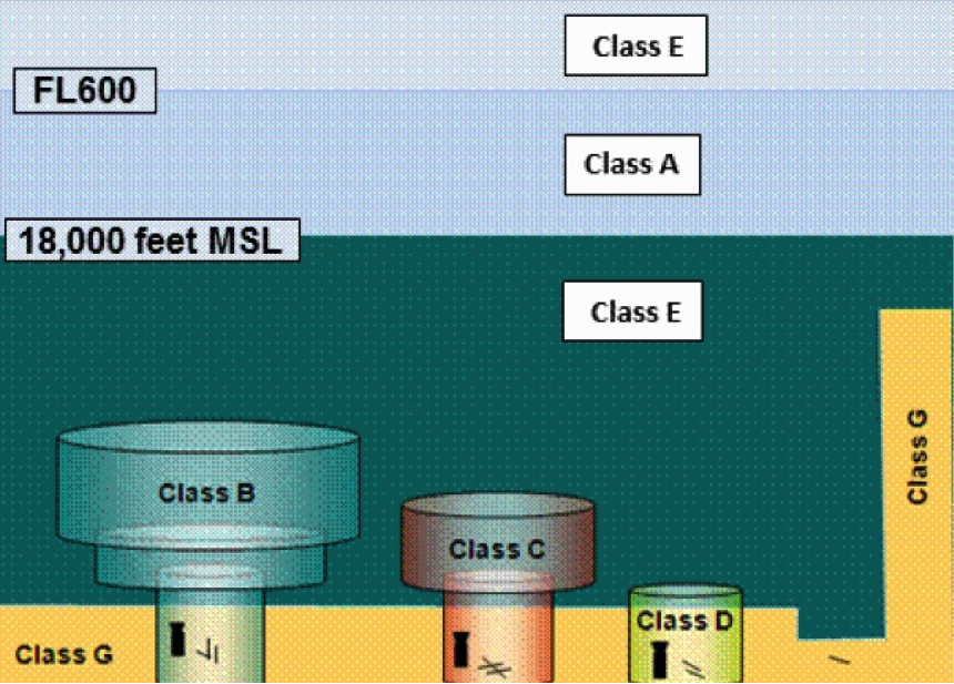
To Read
- Read section 5.3 of chapter 5 in Introduction to Unmanned Aircraft Systems. It briefly describes the different classes of the NAS.
- Review materials on the High Adventure website [78] which provides more details on the NAS.
Flight Operations
In most cases, operating a UAS requires employment of similar logistics as those needed for manned aircraft. Large UASs such as the Northrop Grumman’s Global Hawk call for operation requirements similar to those needed to fly a large Boeing aircraft. The Global Hawk, which is the size of a Boeing 737, requires runways for takeoff and landing. It can fly over 60,000 feet, cruise at 310 knots, and has an endurance of 36 hours. On the other hand, small UASs weigh only a few pounds and do not need airports or runways for takeoff and landing. Different UAS sizes and sophistication also require different personnel skills and requirements.
Launch and Recovery
There are many ways in which a UAV can be launched, some of which are very complex while others are as simple as a hand toss into the air. Some UASs, such as target drones, are air-launched from a fixed wing aircraft. Usually, large UASs are equipped with wheels for takeoff and landing and do not need special equipment, while smaller UASs needs a variety of launch and recovery strategies depending on the complexity of the system. Many small and medium size UAS launch systems have a requirement to be mobile, or in other words, to be mounted on a truck or a trailer. Such mobile launchers fall within one of the following types:
- Rail Launchers
- Pneumatic Launchers
- Hydraulic/Pneumatic Launchers
For more details on these launchers, refer to chapter 17 of the supplemental textbook Introduction to UAV Systems, 4th edition.
Line of Sight (LOS) Operation
Line-of-sight (LOS) operation refers to operating the UAS through direct radio waves. The LOS link provides command and control uplink and product downlink while the UAS operates within a certain distance from the GCS. The link is used to launch and recover the aircraft and perform data acquisition according to the type of payload mission of the system. In the United States, civilian operations are usually conducted on 915 MHz, 2.45 GHz, and 5.8 GHz.
Beyond Line of Sight (BLOS) Operation
Beyond Line-of-sight (BLOS) operation refers to operating the UAS through satellite communications or using a relay vehicle such as another aircraft. The recent advancements in SwiftBroadband service and hardware, including smaller, lighter avionics that don’t compromise on performance or data capacity, allow near-global connectivity to become available to support and enhance UAV operations. SwiftBroadband service is provided by InmarSat Satellite broadband communications. BLOS is usually limited to military UAS operations. Civilian UAS operations do not need BLOS systems for the time being, as their missions are conducted within line of sight range. Civilian operations have access to BLOS via the Iridium satellite system, which is owned and operated by Iridium LLC.
The FAA through its "Partnership for Safety Plan (PSP)" program continue its efforts to team with the industry to help them with the UAS integration. The following organizations were among the entities that FAA is working with to test and try the BVLOS and many of the other UAS integration issues:
1. Amazon Prime A
2. Burlington Northern Santa Fe (BNSF) Railway
3. Drone Racing League (DRL)
4. Florida Power and Light
5. UPS Flight Forward Inc.
6. Wing (an Alphabet company)
7. Xcel Energy
For more information on the PSP, visit this FAA website [86].
The FAA in mid-June, 2021 announced that they are forming a new Aviation Rulemaking Committee, or ARC, to provide recommendations to help the agency develop a regulatory path for routine Beyond Visual Line of Sight drone flights. The committee considers the safety, security and environmental needs, as well as societal benefits, of these operations.
Personnel Qualifications
Unmanned aerial system operators of remote pilots, visual observers, mission planners, and other support staff are responsible to:
- plan and analyze flight missions;
- perform preflight, in-flight and post-flight checks and procedures;
- conduct air reconnaissance, surveillance and acquisition missions;
- launch and recover the air frame from the runway or any other suitable sites or mechanisms;
- perform maintenance on communications equipment and power sources.
According to FAA PART 107, the job descriptions for the following jobs are specified:
- the remote pilot in command (RPIC)
- the person manipulating the flight controls of the small unmanned aircraft system
- the visual observer
According to the FAA, the following operational restrictions apply to all UAS pilots:
- One RPIC must be designated at all times.
- The RPIC will be required to obtain a remote pilot certificate with a small UAS rating.
- The RPIC will have the final authority and responsibility for the operation and safety of a small UAS operation conducted under part 107.
- RPIC must not perform crew duties for more than one UAS at a time.
- Only one RPIC per aircraft is authorized, and the RPIC must be in a position to assume control of the aircraft.
- In case of an in-flight emergency, the RPIC will be permitted to deviate from any rule of part 107 to the extent necessary to meet that emergency.
- The RPIC (who is a certificated airman) can supervise another person’s manipulation of a small UAS’s flight controls. A person who receives this type of supervision from the remote pilot in command is not required to obtain a remote pilot certificate to manipulate the controls of a small UAS as long as the remote pilot in command possesses the ability to immediately take direct control of the small unmanned aircraft.
As for the visual observer job, the FAA requires:
- A visual observer is a person who assists the remote pilot in command and the person manipulating the flight controls of the small UAS (if that person is not the remote pilot in command) to see and avoid other air traffic or objects aloft or on the ground.
- The visual observer is an optional crew member who will not be required to obtain an airman certificate.
- No Airman Certification or Required Training of Visual Observer.
- If used, observers are considered crew members.
- If used, observers must not perform crew duties for more than one UAS at a time.
- Observers are not allowed to perform concurrent duties both as UAS pilot and observer.
- For more details on the qualifications of each of the above-mentioned jobs, refer to section 16 of the FAA UAS Operational Approval policy N 8900.227 document.
As for the crew in general:
- The remote pilot in command, the person manipulating the flight controls of the small UAS (if that person is not the remote pilot in command), and the visual observer are to maintain effective communication.
- The remote pilot in command determines how that communication will take place.
- Such communications can be accomplished at a distance through technological assistance.
- The remote pilot in command, the person manipulating the flight controls of the small UAS, and the visual observer must always have visual-line-of-sight capability even if they do not exercise it.
Several agencies started providing training and issuing a UAS operator certification to support newcomers to the UAS business, such as the one in the following links:
- UAS Training Vendor 1: RPAS Training and Solutions [87]
- UAS Training Vendor 2: Unmanned Vehicle University [88]
- UAS Training Vendor 3: Drone Pilot Ground School [89]
To Read
- Read section 5.6 of chapter 5 in Introduction to Unmanned Aircraft Systems. It briefly describes the UAS operations.
- Read section 5.7 of chapter 5 in Introduction to Unmanned Aircraft Systems. It briefly describes the personnel qualifications.
To Do
- Review section 3 of the materials on the Federation of American Scientists [48] website, which provides details on UAS operations.
- Review section 16 of the document “Unmanned Aircraft Systems (UAS) Operational Approval” [79] to stand on the qualification of the UAS operation personnel.
Summary and Final Tasks
Summary
Congratulations! You've finished Lesson 5, Fundamentals of Unmanned Aerial System Operations. You should find by now that you are comfortable with describing different UAS classes, listing UAS system elements, designing a concept of operating a UAS, assessing risk surrounding a UAS operation, understanding FAA regulations, defining the operation criteria for different classes of the national airspace, and understanding the guidelines for UAS flight operations. If you feel that you are not comfortable with any of the previously listed subjects, then you need to review the lessons notes and/or contact me.
Final Tasks
| Task | Description |
|---|---|
| 1 | Complete the Lesson 5 Quiz |
| 2 | FAA Roadmap Discussion Forum: Review the 2013 FAA roadmap document in Canvas. As you may notice, the FAA is serious about integrating commercial UASs into the National Air Space (NAS) starting in 2015. Considering the state of technology in manufacturing small UASs and the lack of Sense-and Avoid instruments on board of such small UASs, do you expect any obstacles in the face of integrating small commercial UASs into the NAS according to the FAA proposed road map (i.e., the FAA may restrict the use of certain sizes of UASs for not being equipped with enough safety features)? Post your opinion on the discussion and respond to at least one peer posted opinion on the subject. The deadline for submission is at the end of Lesson 6; you will have two weeks to participate. (3 points or 3%) |
| 3 | Final Project Milestone: Submit final project idea/proposal in the Final Project Proposal drop box in Lesson 5 |
| 4 | Submit your "CONOP and Risk Assessment" assignment report |
Lesson 6: Aviation Regulatory and Certificate of Authorization (COA) Process
Lesson 6 Introduction
Welcome to Lesson 6! In this module, you will become familiar with the current FAA regulations that govern UAS operations and the ongoing efforts to integrate their operations into the National Airspace System (NAS). On top of it are the latest rules known as PART 107. You will also explore the current recreational versus public or commercial operations of UAS, be familiar with the Certificate of Authorization (COA), Certificate of Waiver, and Airworthiness certificate and how to apply for one, and examine issues related to privacy that are of concern to both the government and industry. You will be asked to choose your application materials and organize them for your COA or Part 107 waiver application. The COA/Part 107 waiver project includes a few graded components that will be submitted in the different sections of the lesson. During this lesson, you will be engaged in discussions with fellow students on several topics related to the lesson objectives. Participation in these discussions is mandatory wherever it is requested.
Lesson Objectives
At the successful completion of this lesson, you should be able to:
- recognize the differences between standards and regulations;
- describe the rules and regulations associated with operating a UAS in the United States of America;
- interpret the FAA restrictions on operating a UAS for commercial use; and
- prepare an application for Certificate of Authorization (COA) or PART107 Certificate of Waiver.
Lesson Readings
- Sections 3.1 and 3.2 of Watts, et al., "Unmanned Aircraft Systems in Remote Sensing and Scientific Research: Classification and Considerations of Use" [90]
- Read the FAA "Literature Review on Detect, Sense, and Avoid Technology for Unmanned Aircraft Systems [91]
- Chapter 5 of textbook 1: Barnhart, et al., Introduction to Unmanned Aircraft Systems, 2nd edition
Review the following:
- Review the FAA "Integration of Civil Unmanned Aircraft Systems (UAS) in the National Airspace System (NAS): Roadmap." [92]
- Review the FAA "Model Aircraft Operating Standards. [93]"
- Review the FAA "Notice of proposed rulemaking (NPRM) [94]."
- Review PART 107 [72] “Operation and Certification of Small Unmanned Aircraft Systems.”
- Review the article "What You Need to Know to Legally Operate Your Drone Under New FAA Regulation." [77]
- Review the FAA "National Policy on the Unmanned Aircraft Systems (UAS) Operational Approval." [95]
- Review sample of PART107 Certificate of Waiver [96].
- Review several COAs issued by the FAA. [97]
- Review the information provided in this COA information template document [98]before completing your COA application.
- Review the samples of issued COAs that is provided to you under the "Example_COAs_from_FAA" in the Modules section.
Lesson Activities
- Participate in the "Differences between Rules and Regulations discussion forum."
- Start working on the "COA application draft."
- Submit your results for exercise 1 data processing in Pix4D.
- Start processing the dataset for exercise 2 using Pix4D software.
- Complete the Lesson 6 Quiz.
The Need for Regulations
The Federal Aviation Administration (FAA) was created in 1958 in response to a series of fatal accidents and midair collisions involving commercial aircraft. The FAA was mandated to develop plans and policies for the use of navigable airspace to ensure the safety of aircraft and the efficient use of airspace. Prescribed air traffic regulations should cover the flight of aircraft (such as safe altitudes) for navigating, protecting, and identifying aircraft; protecting individuals and property on the ground; using the navigable airspace efficiently; and preventing collision between aircraft, between aircraft and land or water vehicles, and between aircraft and airborne objects.
Since the creation of the FAA, American airspace has become one of the most regulated fields in the United States. With the introduction of UASs, the FAA has had to examine and ensure that these pilotless aircraft can operate safely and meet all the above mentioned regulations. The NAS is already congested with piloted aircraft, and adding a swarm of UAVs requires thoughtful planning. The FAA's main mandate is to ensure that UASs do not endanger current users of the NAS (including manned or other unmanned aircraft) nor compromise the safety of the people and property on the ground.
When it comes to the safe operation and integration of the UAS into the NAS, one of the main concerns that the FAA has is the lack of detect, sense, and avoid capability of the current UAS technology. The FAA did a thorough literature review to stand on what is possible and what is not along this line. The article listed in the reading assignment of this section details the FAA quest for the detect, sense, and avoid possibilities.
To Read
- Read sections 3.1 and 3.2 of the article “Unmanned Aircraft Systems in Remote Sensing and Scientific Research: Classification and Considerations of Use [90]," which briefly discusses regulations governing the use of the UAS.
- Read the FAA "Literature Review on Detect, Sense, and Avoid Technology for Unmanned Aircraft Systems [91]" which details the FAA quest for technology to support detect, sense, and avoid capability of the UAS.
Current Status of FAA Guidelines on UAS
In this section, you will explore the current regulations that govern UAS operations and the efforts underway to integrate their operations into the National Airspace System (NAS). The status of UAS regulations can be considered in relation to two different eras. The first one preceded the provisions of the FAA Modernization and Reform Act of 2012 (P.L. 112-95), and the second is what we are currently dealing with after the 2012 provision. During both eras, the FAA regulations on operating a UAS in NAS were very strict and in fact prohibited civilians from flying UASs until Part 107 went into effect on August 29, 2016. In 2008, The Aviation Safety Unmanned Aircraft Program Office (UAPO) of the FAA issued the Interim Operational Approval Guidance 08-01. “Interim Operational Approval Guidance, Unmanned Aircraft Systems Operations in the U. S. National Airspace System” provided guidance to help determine if unmanned aircraft systems (UAS) should be allowed to conduct flight operations in the U. S. national airspace system (NAS). On July 30, 2013, the FAA issued a national policy (N 8900.227) for reviewing and evaluating the safety and interoperability of proposed Unmanned Aircraft Systems (UAS) flight operations conducted within the United States (U.S.) National Airspace System (NAS) under the subject “Unmanned Aircraft Systems (UAS) Operational Approval.” The new national policy defined in details the methods of the UAS operational approval through the issuance of either a COA for public aircraft operations or a Special Airworthiness Certificate for civil operations. All guidelines and regulations are jointly developed by the following entities within the FAA:
- the Unmanned Aircraft Program Office (UAPO), FAA Aircraft Certification Service (AIR-160)
- the Production and Airworthiness Division, FAA Aircraft Certification Service (AIR-200)
- the Flight Technologies and Procedures Division, FAA Flight Standards Service (AFS-400)
- the FAA Air Traffic Organization’s Office of System Operations and Safety, (AJR-3)
Originally, the Certificate of Authorization, or COA, was limited to public agencies and no commercial agency was granted a COA. Even for public agencies, COA cannot be guaranteed, and COAs may take different lengths of time or have some restrictions built in, according to the FAA document N 8900.227, which states “because of the uniqueness of various UAS flight operations, each application must be evaluated on its own technical merits, including operational risk management (ORM) planning. Each application may require unique authorizations or limitations directly related to the specific needs or capabilities of the UAS and/or the proposed specific mission and operating location.”. However, during 2015, the FAA started issuing grants exemption for commercial entities to fly UAS for commercial use under strict limitations. The FAA based such grant exemption on section 333 of the FAA Modernization and Reform Act of 2012. [99] An exemption according to section 333, allows commercial companies to fly UAS, after they apply for COA, of course, for commercial use. Even with the heavy restrictions that surrounded these exemptions, the move was welcomed by companies who are planning to use UAS for various commercial tasks, and it was considered to be the baby step that they were waiting for.
The previous surprising move by the FAA was followed by three unprecedented moves.
Certificate of Waiver, Airworthiness Certificates, and Certificate of Authorization (COA)
As you may have noticed from the materials you reviewed in the previous section, no one is allowed to fly a UAS without prior approval from the FAA. Any UAS operation in the United States has to occur in one of two ways. Either the UAS belongs to a public agency (i.e., governmental) and then requires a COA or operates under Part 107 rules, or it belongs to to a civilian entity and therefore requires adherence to Part 107 rules and perhaps a special airworthiness certificate or a waiver. For manned aircraft, the FAA requires several basic steps to obtain an airworthiness certificate in either the Standard or Special class. The FAA may issue an applicant an airworthiness certificate when:
- the registered owner or operator/agent registers the aircraft,
- the applicant submits an application through the dedicated portal, and
- the FAA determines the aircraft is eligible and in a condition for safe operation.
The process for a UAS is different for the time being, as it is approached through either a COA or a special airworthiness certificate, as was discussed above. For UAS, the FAA may consider an airwortiness letter like the following:
"To Whom It May Concern:
The eBee small Unmanned Aircraft System has been inspected and reviewed on behalf of XY organization by qualified individuals and a determination has been made based on testing data and evaluation data provided by the manufacturer that the aircraft is serviceable and airworthy for the intended use as advertised by the manufacturer, subject to the warrantees and representations offered by said manufacturer.
Sincerely,
John Doe, System Engineer, XY organization"
Just to reiterate, the process of requesting a UAS operation within the territorial airspace of the United States (the airspace above the contiguous United States, Alaska, Hawaii, U.S. territories, and U.S. territorial waters) differentiates depending whether the applicant is a public agency or a civilian entity. The methods of operational approval are the issuance of either a COA for public aircraft operations or for civilian operators is either to operate under PART 107 for UAS that weighs less than 55 lbs or operators need to apply for an exemption under the Special Authority for Certain Unmanned Systems (49 U.S.C. §44807) [100]. Special Airworthiness Certificate [101] is needed for civil operations under certain conditions. The FAA on its website allowed civil users to apply for a COA, it is not needed anymore, through a dedicated portal. This Form shows the web application interface [102]. The form is provided to show the actual interface for the COA application and the required materials and all applicants have to provide the required submissions through the portal. To apply for a COA, go to the FAA UAS Civil COA Portal [103]. You will need to create an account on the FAA website before you proceed with your application. Anyhow, if you are planning to apply for a COA, be prepared to provide the following materials and information through the portal and/or when the FAA ask you later if needed:
Sample Certificate of Authorization Application
This link provides a sample of COA application provided by the FAA on their website Sample COA application form from the FAA website [104].
Certificate of Authorization Application Components
Make sure that your COA application provide the FAA with the following components:
- Applicant Contact Information:
- 333 Exemption number if any
- name, address, phone, and email
- Purpose of the operation and the requested exemption, if any
- Aircraft System
- description
- picture
- airframe
- dimensions
- power source
- electric, internal combustion, etc.
- weight (gross takeoff weight)
- avionics
- performance
- endurance
- range
- speed
- operating altitude
- turing radius
- climb/decent rates
- Airworthiness statement and documentation
- Communications
- pilot/operator to aircraft
- pilot/operator to observers
- communication within the airspace
- air traffic control procedures and frequencies
- local airspace frequencies
- video/data
- FCC approved frequencies
- ranges
- operational communications range
- backup communication
- radios
- cell phones/landlines
- Ground Control Station
- description
- picture
- capabilities
- setup and operations
- frequency management
- FCC approved equipment
- range
- ConOps, Emergency Procedures, and Risk Mitigation
- identify, control, and document potential hazards (examples)
- human factors
- machine
- media
- management
- mission
- assess the risks (examples)
- weather induced flight cancelation or termination
- lost communication
- loss of payload
- aircraft fire
- analyze risk control measures (examples)
- mishap notification
- access and contact procedures to fire and rescue
- programmed procedure for lost links
- make control decisions
- implementation of risk controls
- review and improvement process
- Flight Operations Area and Time
- COA Location
- boundary points (or center point if circular) recorded in coordinates
- Time of Day
- Launch and Recovery Points
- launch and recovery points recorded in coordinates
- Lost Link/Rally Points
- lost link/rally points recorded in coordinates
- Description of airspace class(es) (A, C, D, E, or G) for proposed operations and surrounding area
- Map and/or aeronautical chart depicting the flight operations in relation to ground references and airspace
- VFR Chart
- Aerial image (i.e. Google Earth/Maps)
- Show COA area with boundaries clearly marked.
- Show planned launch, recovery, and rally points.
- FAA coordination and concept of operations plan (Flight Standards District Office, Air Traffic Control Tower, etc.)
- Planned nominal flight operations in proposed airspace
- Altitude (minimum and maximum)
- Security for crew
- Launch and Recovery Procedures
- Primary/planned launch and recovery location(s)
- Launch and recovery checklists and procedures
- Takeoff and Landing or Fixed Wing launch and recovery methods
- Launch (examples)
- Hand-held
- Rail
- Catapult
- Support vehicles/equipment
- Weather limits
- Recovery (examples)
- Net
- Grass
- Weather limits
- Landing speed
- Launch (examples)
- Lost Communications Procedure
- Return to Base (RTB) procedures
- Lost communication between pilot and Air Traffic Controllers
- Lost communication between pilot and observers
- Lost Link Mission Procedures
- Internal navigation systems failure
- Control systems failure
- 5%">Low/lost battery
- Length of time to identify lost link
- Procedure to re-establish link
- Procedure if link is not re-established
- Platform actions if link is lost
- Notification procedures in the event of lost link
- Operator (Pilot) and Visual Observers
- Crew qualifications
- Pilot certifications
- Aircraft currency
- Required currency of medicals
- Platform training and currency
- Crew resource management (CRM) approach
- Communications and coordination for operations
- Provision for UAS operations (single platform at a time)
Part 107 Certificate of Waiver
Public agencies or private individual or business who wants to be exempted to fly UAS under certain conditions can apply for Certificate of Authorization (COA) [105]. The introduction of Part 107 removed many hurdles from the face of operating civilian UAS under many conditions. However, for conditions that are not listed or described directly under Part 107 regulations, a civilian operator can apply for a waiver. The FAA states "A waiver is an official document issued by the FAA which approves certain operations of aircraft outside the limitations of a regulation. You may request to fly specific drone operations not allowed under part 107 by requesting an operational waiver. These waivers allow drone pilots to deviate from certain rules under part 107 by demonstrating they can still fly safely using alternative methods." . The following table illustrate the conditions under which one needs to apply for a waiver to operate under Part 107.
List of operations that require a waiver under Part 107 (source FAA [106])

How To Apply For a Waiver?
One can apply for a waiver through the FAA website [106]. The FAA details the guidelines for the waiver application and the required information. Pay close attention to the "Waiver Safety Explanation Guidelines for Part 107 Waiver Applications" that you may encounter in the DroneZone operational waiver application. For the waiver application, the FAA required extensive details on:
- Describing the proposed operation
- Describing possible operational risks and methods to mitigate those risks
The following items are required for the "Waiver Safety" part of the application as adopted from the FAA website [107]:
Describe Your Proposed Operation(s)
Operational Details
- Where do you plan to operate?
- Consider providing latitude/longitude and a detailed map of your planned flight area.
- How high will you fly your aircraft (maximum altitude above ground level)?
- Do you want to fly in controlled airspace (Class B, C, D, surface E)?
- If yes, please see 14 CFR §107.41 [108] and our Flying Drones Near Airports (Controlled Airspace) – Part 107 page [106]
- Are there any other kinds of airspace within 5 miles of any planned flight area?
- What kind of area(s) will you fly over?
- For example: rural, sparsely populated, congested, populated, a neighborhood, within city limits, large outdoor gathering of people, a restricted access site, etc.
Small UAS Details
- What kind of UAS will you use to fly the operations requested in this application?
- For example: multi-rotor, fixed wing, hybrid (both multi-rotor and fixed wing), single rotor, lighter than air, etc.
- What is your UAS's power or energy source in flight?
- What is your UAS's maximum flight time (in minutes), range (in feet), and speed (in miles per hour)?
- How big is the aircraft (length/width/height in inches)?
- How do you ensure the aircraft only flies where it is directed (i.e. ensure containment)?
- For example: geo-fencing, tether, etc.
- What kind of termination system, if any, does the UAS have?
- For example immediate flight termination switch
- How much will the aircraft and its payload weigh when flying?
- If the aircraft carries any external or internal load (or object), how is the load secured?
- What, if any, external or internal load (or object) could be dropped from the aircraft when flying, and how will you assure the safety of people, or other people's property, if it is dropped or detached when flying?
Pilot/Personnel Details
- What minimum level of experience will the Remote Pilot in Command (Remote PIC) have to fly under this waiver?
- How many personnel (including the Remote PIC) will you use for operations under this waiver (minimum needed)?
- What kind of training, if any, will personnel (e.g. visual observer(s)) have prior to flying under the waiver?
- How will the personnel be trained?
- How will the Responsible Person know the other personnel are competent and have operational knowledge to safely fly the UAS under the waiver conditions?
- If personnel will be tested, what kind of testing will be performed, and how will evaluations be conducted and documented?
- How will personnel maintain the knowledge/skill to fly under this waiver? Will recurrent training or testing be required?
Describe Operational Risks and Mitigation
Provide, to the greatest extent possible, how you propose to address or lessen the possible risks of your proposed operation. This could include using operating limitations, technology, additional training, equipment, personnel, restricted access areas, etc. When reviewing the questions for each section below, the FAA's primary concerns are:
- How you will ensure your operation(s) remains safe at all times, even in unusual circumstances.
- What kinds of circumstances could arise, and how you plan to handle each.
The following questions [109] are associated with each waivable section of part 107. Only answer the questions for the regulatory section applicable to the application you will submit:
- 107.25 Operations from a moving vehicle or aircraft
- 107.29 Daylight operation
- 107.31 Visual line of sight aircraft operation
- 107.33 Visual observer
- 107.35 Operation of multiple small unmanned aircraft
- 107.37 Operation near aircraft
- 107.39 Operation over people
- 107.51(a) Operating limitations: ground speed
- 107.51(b) Operating limitations: altitude
- 107.51(c) Operating limitations: minimum visibility
- 107.51(d) Operating limitations: minimum distance from clouds
NOTE: The list of questions may not be all-inclusive. You may need to provide additional information based on your specific operation.
To Do:
- Read chapter 4 of the textbook "Introduction to Unmanned Aircraft Systems."
- Review the FAA national policy on the Unmanned Aircraft Systems (UAS) operational approval. [95]
- Review the samples COA applications [110] that you may benefit from for your COA application.
- Review the samples of valid operational Part 107 Waivers [111].
Application for the Certificate of Authorization (COA) or Part 107 Waiver
In this section, you are expected to develop and submit the required materials for the COA or Part of 107 waiver application for the platform you selected in the activities of Lesson 1. It is helpful to review previously submitted COA or Part 107 waiver applications available on the FAA website before populating your own documentation, so you can become familiar with the format, required materials, and depth of information. The following is a brief list about the materials you may need in order to complete the COA or Part 107 waiver application for your platform:
- Aircraft system
- Communications
- Ground Control station
- Emergency procedures
- Flight operations area
- Launch and recovery
- Lost communications
- Lost link mission
- Operator and visual observers
Make sure to incorporate risk mitigation strategies and address the integration of automation and autonomy in your system in the various sections as appropriate. More details on the information required for a COA or Part 107 waiver application can be found in the template provided. The link to the FAA site provided above also provides plenty of examples on COA and Part 107 waiver applications.
To Read
- Visit the Federal Aviation Administration website [97] to review several COAs issued by the FAA. Make sure that you review several applications from various organizations and note differences in their platforms and procedures.
To Do
- Review the information provided in this COA information template document [98]before completing your COA application.
- Review the samples of issued COAs that are provided to you in the module entitled "Example_COAs_from_FAA".
- Visit the FAA website and stand on current issued Part 107 waivers.
Summary and Final Tasks
Summary
Congratulations! You've finished Lesson 6, Aviation Regulatory and Certificate of Authorization Process (COA). I hope you digested the materials very well, as they are essential to understanding the circumstances of operating any UAS in the U.S. The exercise of developing your own COA or Part 107 waiver application will enable you to manage a UAS operation, as it has provided you with crucial knowledge about logistics and safety concerns regarding UAS operations. The exercise not only had provided you with FAA rules and regulations, but has also given the necessary technical knowledge about different sub-systems of the UAS.
Final Tasks
| 1 | Complete the Lesson 6 Quiz. |
|---|---|
| 2 | For this exercise, you can claim that you are representing a public agency, in which case you need to apply for COA or a civilian operator, in which case you need to apply for Part 107 waiver. Recognizing that a public agency can also apply for Part 107 waiver, start working on your "COA application draft" or "Part 107 waiver draft". Develop draft materials for your application for the UAS you selected in section 2.7 of Lesson 2. Choose a geographic location for your system operations. Name the civilian application you are going to use the system for. You may find that all technical specifications/information about your UAS is not available or publicly published, in which case you need to adopt published technical specifications for a similar UAS or from an existing COA or a Part 107 waiver. Your report should contain at least 20 pages, but not to exceed 30 pages (single line spacing). Upon completion, submit your completed word document(s) in the drop box. (7 points) |
| 3 | Submit your results for exercise 1 data processing in Pix4D |
| 4 | Participate in the discussion for Lesson 6 "Differences Between Rules and Regulations". Deadline for this assignment is at the end of Lesson 7. |
| 5 | Start processing the dataset for exercise 2 using Pix4D software. |
Lesson 7: Products Generation
Lesson 7 Introduction
Welcome to Lesson 7! In this lesson, you will understand and be familiar with the photogrammetric process, the processing systems, and data generation from an image-based UAS. Most applications of the UAS today include one form or another of a camera system (video or still camera) from which different interpretations and therefore different applications are evolved. You will also develop understanding of processes such as aerial triangulation and ortho rectification, which are the backbone of any image processing facility. The photogrammetric textbook Elements of Photogrammetry with Applications in GIS will be your companion, beside the lesson notes, in understanding the topic.
Lesson Objectives
At the successful completion of this lesson, you should be able to:
- understand the concept of sensor and product geolocation;
- understand the concept of direct geo-referencing;
- understand the concept of aerial triangulation;
- outline complete UAS data processing workflow;
- distinguish between different products obtainable from different UAS payload sensors.
Lesson Readings
- Chapters 1, 11, 16, and sections 17-1 and 17-9 of Chapter 17 of textbook 3: Wolf, et al., Elements of Photogrammetry with Applications in GIS
Lesson Activities
- Complete the Lesson 7 Quiz.
- Work on your final project report and presentation. (Due next week.)
- Practice generating DSM and ortho mosaic at different GSDs using Pix4D and evaluate the differences in qualities.
- Continue working on your COA Application and the Final Project Report.
The Photogrammetric Process
In this section, you will understand the photogrammetric process and the different steps the product goes through in order to develop an ortho photo or digital elevation model.
Figure 7.1 illustrates the different steps of processing that imagery from a UAS is subject to in order to produce a mapping product such as an ortho photo or digital elevation model.
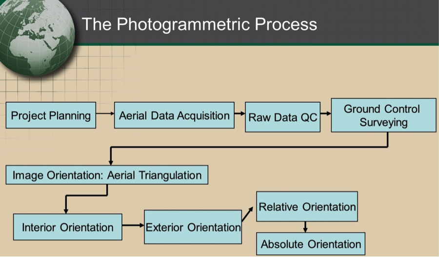 [112]
[112]
As we learned in Lesson 4, the process starts with the mission planning process. Once all the parameters and requirements are defined for the mission, a flight plan is developed and aerial imagery is acquired according to the project specifications. The resulting imagery will be reviewed to assure the expected quality. Following the image QC, the field work will be conducted to survey the necessary ground controls. The ground controls survey can be conducted either before the imagery acquisition, or after it is completed.
Once the imagery acquisition and the ground control survey are completed, work can begin on the process of aerial triangulation. Aerial triangulation, as it will be described in section 7.2, is performed to determine the position and the orientation of the camera at the moment of exposure of each image. It includes a few processing concepts, such as interior and exterior orientations, relative orientation, and absolute orientation. Aerial triangulation is achieved through processing software that is based on rigorous mathematical models based on least squares. Once the aerial triangulation is completed, the imagery is ready to go through other processing steps such as ortho rectification and digital elevation modeling.
To Read
- Chapter 1 of Elements of Photogrammetry with Applications in GIS, 4th edition.
Imagery Geo-location
In this section, you will learn about the concept of geo-referencing imagery, which is an important concept. Without it, no further photogrammetric processing of the imagery can take place.
In order to utilize the photogrammetric mathematical model, i.e., the collinearity condition, for the production of any mapping products, the following information needs to be made available:
- The exterior orientation parameters for every image: Six parameters which represent the camera attitude or orientation represented by the three rotational angles omega, phi, and kappa, and camera position, which is represented by the three coordinates Easting, Northing, and Elevation at the moment of image exposure.
- The camera interior geometry parameters: The calibrated lens focal length, the principal point coordinates, and the lens distortion as it was discussed in lesson 6.
- The size of the CCD array: The number of pixels contained in the CCD array along the width and the height of the array.
- The physical size of the CCD: Usually provided in microns such as 14 u (1 mm is equal to 1000 um).
- Ground Controls: A ground control is a feature in the imagery with known accurately surveyed coordinates. Depending on the required accuracy of the final products, ground controls can be omitted in some situations.
In this section, we will focus on the process of determining the six exterior orientation parameters. The camera position can be measured accurately using the airborne GPS technique using a GPS antenna on board the UAS. The three camera positions can also be computed using the process of aerial triangulation, as we will discuss soon. However, there are two methods for determining the camera attitude or orientation, and those are the aerial triangulation process and the direct measurement from the IMU, as we discussed in Lesson 6.
Aerial Triangulation and Bundle Block Adjustment
Aerial triangulation is usually performed on a photogrammetric block (Figure 7.2), which consists of all the imagery acquired over the project area. Figure 7.2 illustrates a photogrammetric block of imagery consisting of three strips, each of which has multiple overlapping images. Also shown are the different types of image overlaps. The top and middle strips contain images with 60% forward lap, while the bottom strip contains imagery with 80% forward lap. You may also notice in the figure that the middle and the bottom strips are overlapping by the amount of 30%. Such overlap is called side lap.
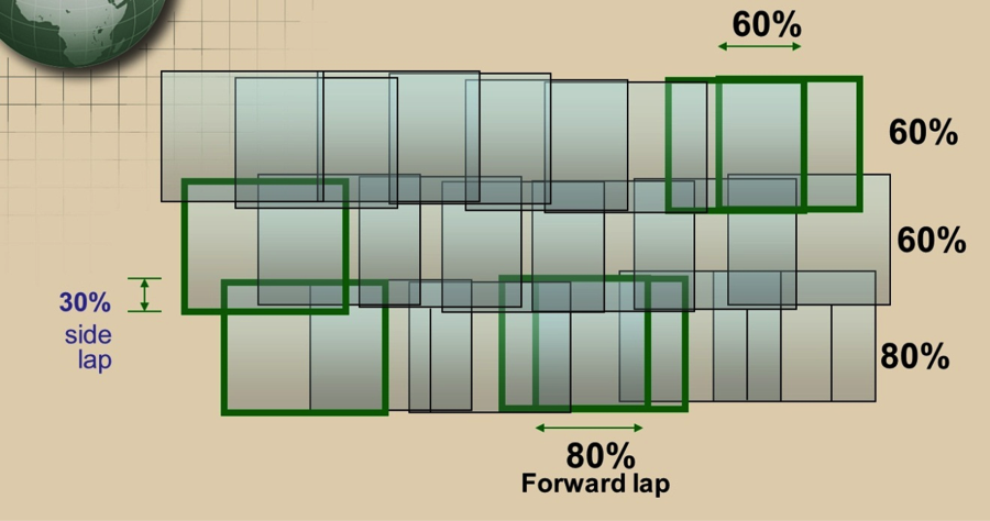
In the last section (the photogrammetric process), we mentioned a few terms related to aerial triangulation. We will briefly describe these terms in the following sub-sections:
Relative Orientation
Relative Orientation is the process of orienting images relative to one another (i.e., it recreates the “relative” position and attitude of the images at the instants of exposure), as illustrated below. Figure 7.3 shows four images that are connected to each other in space through the aircraft/GPS trajectory but are not necessarily connected to the ground datum (i.e., they are floating in space).
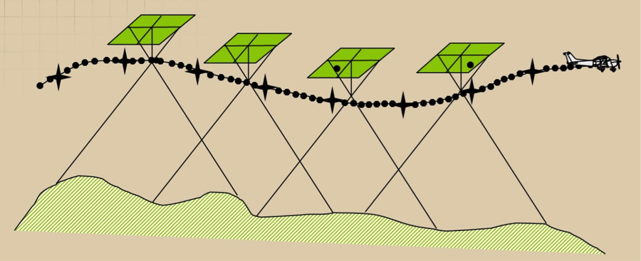
Relative orientation is an important process that must be performed before we scale the imagery to the ground datum through the process of absolute orientation, which will be discussed in the next section. To form a cohesive block, all images in the block should be relatively oriented with respect to each other through the process of relative orientation.
Absolute Orientation
The process of leveling and scaling the stereo model (formed from two images) with respect to a reference plane or datum using ground control points is shown in Figure 7.4. Figure 7.4 represents the same four images as Figure 7.3, but this time the block was tied to the ground datum through the use of seven ground control points (represented by the black stars).
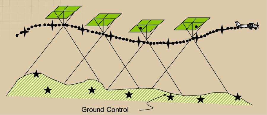
Without performing the absolute orientation process, the generated map would not be specifically associated with a certain location in space. Generating maps that have geo-location information such as datum and coordinates systems can only happen after the process of absolute orientation is performed following relative orientation.
Exterior Orientation
Exterior orientation of a photograph defines its position and orientation in the object space. There are six elements of exterior orientation, X, Y, and Z of the exposure station position, and the three angles that define the angular orientation: ω, φ, and κ. The six elements of exterior orientation are not known and must be computed through a process called space resection within the aerial triangulation process. Here is the definition of the three orientation angles illustrated in Figure 7.5:
-
Omega (ω): Rotation about the x axis. It is equivalent to the angle Roll of the navigation system.
-
Phi (φ): Rotation about the y axis. It is equivalent to the angle Pitch of the navigation system.
-
Kappa (κ): Rotation about the z axis. It is equivalent to the angle Yaw of the navigation system.
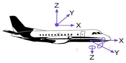
Knowing the six exterior orientation parameters for an image is necessary for any photogrammetric processing aimed at creating products from such an image. Whether you perform map compilation on a stereo plotter or generate an ortho image, the six exterior orientation parameters need to be computed before you start the production process.
Space Resection
Space Resection is the process of determining ray intersection in space to conclude camera position. See Figure 7.6. The method of space resection is a purely numerical method using collinearity equations to simultaneously yield all six elements of exterior orientation (X, Y, Z , omega, phi, and kappa). Once these elements are known, a stereo plotter can measure the photo coordinates of any point in a photo (x,y) and the ground coordinates can be computed. Ortho rectification software also utilizes space resection for ortho-rectifying an image. Figure 7.6 illustrates six images. Each of them has rays from the ground entering the camera through the lens. The intersection of the rays entering the camera at point "O" represents the photo center location, which is important for the determination of the exterior orientation parameters described earlier.
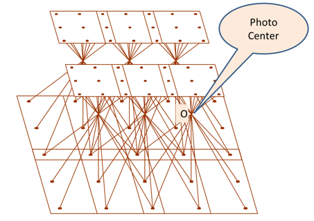
Aerial triangulation
Aerial triangulation can be defined as the process of densification of a sparsely distributed horizontal and vertical control network through:
- measurements performed on overlapping aerial photographs,
- known ground control points coordinates on the ground, and
- mathematical modeling and solution.
A conventional (film based) aerial triangulation process consists of the following steps:
- preparation
- point marking (for tie points and pass points marking)
- measurement
- computation
Data Preparation: Using a stereoscope, three points are selected down the center of each photo, approximately 1” from the top and bottom and at the center. These points are also marked on every overlapping photo on which they occur. They are often called “pass points” along strips and “tie points” between strips. See Figure 7.7. Ideally, pass points are selected in flat areas of high contrast that are free of obstructions and shadows.
Figure 7.7 represents three overlapping photos that are used to extract pass points between them. Notice that the three middle points for the middle photo (a, b, c) were located and marked on the same locations in the overlapping right and left image. This process is called point marking.
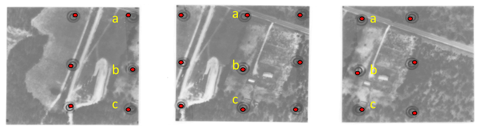
Point Marking: A good point marking device is characterized with:
- precise optics for stereo viewing;
- variable zoom - 6X to 25X;
- laser beams, hot needles, mechanical or electric drills that will remove emulsion from the dispositive;
- the ability to create a very precise circular mark, typically from 40 to 80 microns in diameter.
One of the earliest commercially successful point marking devices was the P.U.G., manufactured by Wild Heerbrugg Instruments, Inc. See Figure 7.8. Over time, pass points marked on dispositive became known simply as pug points.

Point Measurement: A skilled technician with analytical stereo plotting instruments records the location of each previously marked Pass point and tie point on each photograph.
Numerical Computation of Aerial Triangulation: Here is a summary for the steps taken within the processing software:
- Processing numerical observations of individual photographs to build a cohesive block.
- Forming individual photos into strips by successive, relative orientations, using the common primary pass points between overlapping photos.
- Computing Horizontal and vertical coordinates for each strip.
- Converting strip coordinates to ground coordinates using the ground control contained within a given strip.
- Applying simultaneous polynomial equations (horizontal and vertical) to produce final adjusted values for all points.
- Calculating exterior orientation elements for each photo to be used as input to a bundle adjustment program.
Unlike the aerial triangulation of the past, which was performed using film-based imagery instead of digital imagery and optical-mechanical instruments, today aerial triangulation is performed on digital imagery using a complete softcopy approach called softcopy aerial triangulation. In softcopy aerial triangulation, all manual work of points marking and measurements are left to the automation of the software. It is more efficient and more accurate.
Mathematical Model for Aerial Triangulation
The backbone of the computational model in Photogrammetry is based on two equations called the collinearity equations, which are based on the collinearity condition. The two collinearity equations are represented below:
Where,
Xc, Xc, Xc = Camera perspective center
X, Y, Z = ground point position
x, y = point position on image
mii = photo orientation matrix
f = camera lens focal length
x0, y0 = Principal point of autocollimation
Direct Geo-referencing
In the last two decades, navigation technologies have advanced to the point that enabled manufacturers of the Inertial Navigation Systems (INS), usually used for missiles and submarines navigation, to produce an Inertial Measurement Unit (IMU) to accurately measure the orientation of airborne sensors such as cameras and LiDAR. The IMU, which we briefly described in Lessons 2 and 6, are used either to replace the process of aerial triangulation or to assist its solution. Most UAS, including the small ones, carry on board a GPS unit and an IMU unit. Unfortunately, most of these miniaturized low cost IMU that are used for UAS are not accurate enough to replace the aerial triangulation. Such low accuracy IMU is usually used to navigate the UAS but not to support the aerial triangulation. On the other hand, the GPS antenna in most UAS is a survey grade quality that can receive signals from both GPS and GLONASS. Some of the UAS can receive signals from OMNISTAR with real time corrections.
To Read
- Chapter 11 of Elements of Photogrammetry with Applications in GIS, 4th edition
- Section 17-1 to 17-9 of chapter 17 in Elements of Photogrammetry with Applications in GIS, 4th edition
Ground Control Requirement
In this section, we will discuss an important topic to any photogrammetric work: ground controls.
A ground control, which we introduced in the last section, is a target in the project area with known coordinates (X,Y,Z). Accurate, well-placed ground controls are essential elements for any photogrammetric project utilizing aerial triangulation.
There are two standard types of ground control points (Figure 7.9), those are:
- Photo Identifiable (Photo ID): This could be any feature on the ground such as a manhole, parking stripe, etc. (the right two images of Figure 7.9). This type of control does not need to be surveyed before the UAS flies the project, as it can be surveyed later on.
- Pre-marked (Panels): This type is generated by marking or painting certain figures or symbols on the ground before the UAS flies the project (the left two images of Figure 7.9). This type of control also does not need to be surveyed before the UAS flies the project as it can be surveyed later on; however, if temporary markers that can be disturbed or moved are used, they should be surveyed ahead of time..
Many projects make use of one type or the other, or a combination of the two.
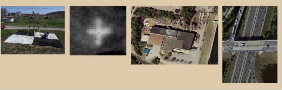
The leftmost image In Figure 7.9 represents a pre-marked control point set on black and white fabric, while the image next to it represent a pre-marked control point that is spray-painted on a sidewalk. The rightmost images represent different types of photo identifiable ground control points. On these images, the user can pick any visible ground feature (such as a parking strip or edge of where the concrete meets the asphalt pavement on a bridge) to use as a control point.
There are two techniques to survey ground control points. The most common one is using RTK GPS techniques, as it is the fastest and least expensive. RTK survey results in a horizontal accuracy of about 2cm and about 3cm vertical accuracy. RTK survey is widely used for mapping projects. The second survey technique which is much more expensive is differential leveling for height determination and static GPS for horizontal survey. Differential leveling results in around 1cm vertical accuracy. Here in the United States, surveying a point using RTK GPS usually costs between $150.0 and $300 depending on the location and terrain. Differential leveling costs around $1,000 to $2,000 per point, again depend on location and terrain. Selecting one type of surveying technique versus another depends on the expected mapping product's accuracy. Consult the American Society of Photogrammetry and Remote Sensing (ASPRS) Positional Accuracy Standards for Digital Geospatial Data [113] and chapter 9 to stand on the accuracy requirement of the ground control based on product accuracy.
Ground control requirements vary from one project to another depending on the project specifications and its geographic extent. Projects with high geometrical accuracy requirements require more ground controls. Figure 7.10 illustrates typical distribution of ground controls in a rectangular shaped project when the aircraft does not carry on board a GPS antenna, resulting in a non-GPS supported aerial triangulation, or what is usually called “conventional aerial triangulation.”
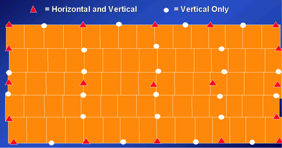
However, most aerial triangulation today is solved with airborne GPS data. Having GPS data in the aerial triangulation process saves a tremendous number of ground controls. Figure 7.11 illustrates the low density of ground controls required for GPS-based aerial triangulation.
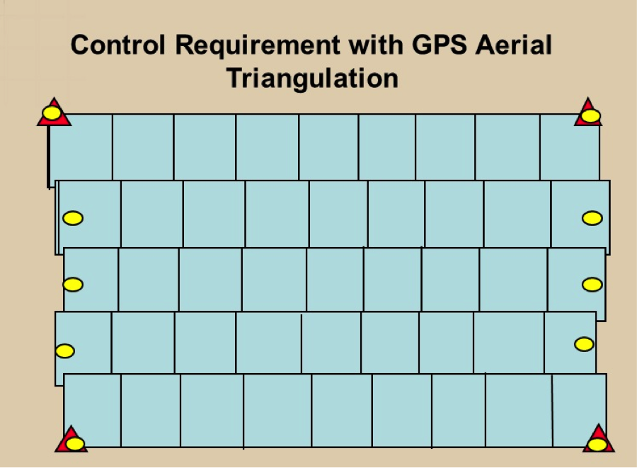
Despite having ground controls only at the edges of the flight line as shown in Figure 7.11, having few additional controls along the interior of the block (see Figure 7.12) is a wise strategy, especially as high accuracy is expected form the aerial triangulation. Savings can be made in the control survey by replacing most of the ground control points at the edges of flight lines with imagery taken with a flight line perpendicular to the project flight lines at each end of the block (see Figure 7.13). Such additional flight lines that are perpendicular to the normal project flight lines are called “cross flight lines.”
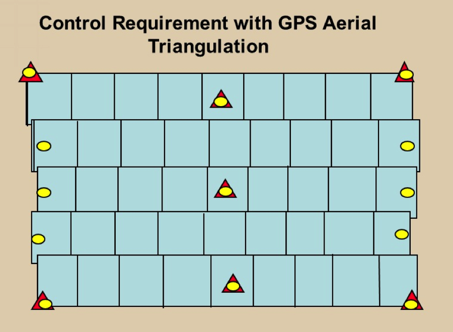
Adding two cross flights (strips) at each edge of the photogrammetric block not only saves on number and cost of the ground control points but it also provides strength to the mathematical model within the bundle block adjustment computations. It helps in modeling and solving GPS and IMU problems.
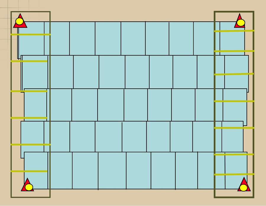
To summarize the subject of ground control requirement for a block, we start with Figure 7.10, which represents the most control consuming case. That is the case of conventional aerial triangulation, where we do not use GPS on the camera during imagery acquisition. Then comes the most efficient method of aerial triangulation, and that is GPS-based aerial triangulation. Figures 7.11 through 7.13 represent different distribution of ground controls for GPS-based aerial triangulation. Each case has its strength and weakness, however, the configuration in Figure 7.13 represents the most economical way when it comes to the reduction in the ground controls requirement.
To Read
- Chapter 16 of Elements of Photogrammetry with Applications in GIS 4th edition
Products Generation
In this section, we will discuss products generated from image-based UAS. Although imagery collected by UAS can be used in a variety of applications in the field of remote sensing, we will focus in this lesson on two main mapping products; those are the ortho photo and the digital elevation model.
Digital Ortho Photo (Ortho Map)
Digital ortho, ortho photo, orthographic image, or ortho map are different names for the same thing. Ortho photo, which I like to call it most of the time, is an image that is corrected (through the process of ortho-rectification) from the effect of terrain relief or sensor tilt to convert it to a unified scale map. Row images taken over variable terrain will have different scales at different locations on the image. Pixels covering the terrain of the ridge of a mountain will cover a smaller spot, as it is closer to the sensor (aircraft), as compared to a pixel covering a valley.
Performing the process of ortho-rectification will sample all these pixels, so each pixel covers exactly the same ground resolution or GSD regardless of where it falls in the image or from which terrain it originated. In other words, ortho-rectification means reprocessing the raw digital image to eliminate the scale variation and image displacement resulting from terrain relief and sensor (camera) tilt.
Because ortho photos are geometrically corrected, they can be used as map layers in GIS, overlaying, management, update, analysis, or display operations. This is a great advantage offered by the ortho photo as compared to the raw imagery.
The five primary ingredients for the ortho photo generation are the following:
- digital imagery;
- digital elevation model or topographic dataset;
- exterior orientation parameters from aerial triangulation or IMU;
- camera calibration report;
- photogrammetric processing software that utilizes collinearity equations.
An ortho photo produced using a digital elevation model for the bare earth (no buildings or trees in it) is usually called “ground ortho.” In ground ortho, the building lean is not removed in the process of ortho rectification, and buildings will appear to lean radially away from the center of the image, as you can see in the image of the World Trade Center in Baltimore on the left side of Figure 7.14. On the other hand, "true ortho" is an ortho where the buildings look as if they are erected straight up or as if you are looking at them from right above the roofs, as is illustrated in the right image of Figure 7.14. True ortho is very useful in urban areas, such as downtowns with tall buildings, as it reveals all the information in the streets and pathways surrounding the buildings. True ortho is computationally intensive and needs three-dimensional models of all buildings in the image, which makes it more costly than ground ortho.
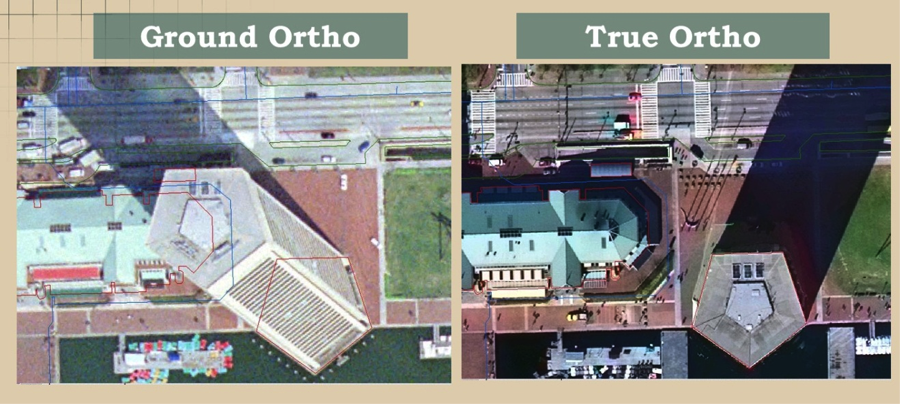
It is very important to evaluate the quality of ortho-rectification, as it may cause some defects. Examples of such common defects are the following:
- Image Completeness:
- Root cause: Image not adequately covered by DEM.
- Image Smearing:
- Root cause:
- anomalies or spike error in DEM;
- excessive relief.
- Root cause:
- Double image on adjacent ortho sheets
- Root cause:
- improper camera orientation;
- inaccurate DEMs.
- Root cause:
- Missing Image
- Root cause:
- improper camera orientation;
- inaccurate DEMs.
- Root cause:
- Mismatch of two adjacent orthos
- Root cause:
- inaccurate camera position and orientation;
- inaccurate DEMs.
- Root cause:
Digital Terrain Data
Similar to LiDAR, stereo imagery can be used to generate accurate digital elevation models. Most software used for UAS data processing has the capability of image matching technique to produce fine quality elevation models that can be used for the ortho rectification process and other terrain modeling purposes. The main ingredients for digital terrain data generation are:
- digital imagery;
- exterior orientation parameters from aerial triangulation or IMU;
- camera calibration report;
- photogrammetric processing software that utilizes the image matching technique.
Until recently, users did not trust the poor quality of the auto-correlated digital terrain data. However, in the last couple of years, software development companies adopted a new algorithm called “Semi Global Matching” or SGM that results in fine quality elevation data that in some ways competes with the elevation model generated by LiDAR. This made users excited again about using imagery for the development of a fine quality digital elevation data. The SGM algorithm is a new image matching approach that originated in the computer vision community. It utilizes auto-correlation matching technique based on aggregates per-pixel matching costs that was not possible with the old auto-correlation algorithms.
As it is in ortho photo production, digital elevation data needs to be evaluated to stand on the quality of the data.
There are a couple of terms that are used in the geospatial community to describe digital terrain data, those are:
- Digital Surface Model (DSM): It is also called reflective surface. Such surface represents the original LiDAR data before any feature such as buildings and trees are removed from it. It also represents the elevation model generated from the image auto-correlation process in photogrammetry. Both LiDAR and image auto-correlation collect data on top of natural ground surfaces such as terrain and trees and man-made materials such as buildings and other structures (Figures 7.15 and 7.16 below).
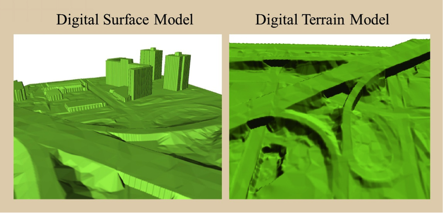
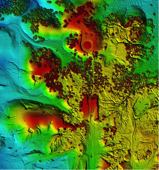
- Digital Terrain Model (DTM): DTM is a term usually associated with digital elevation models of just the ground (trees and man made structures are removed.) DTM is sometimes augmented with 3-D modeling of abrupt changes in the terrain using 3-D lines called break lines. DTM usually contains arbitrary distributed elevation points (not at equal space or grid) called mass points and break lines.
- Digital Elevation Model (DEM): DEM is a term usually associated gridded digital terrain model or points are distributed at equal interval or grid.
-
Triangulated Irregular Network (TIN): The term TIN is used to describe the method that most software uses to model the digital terrain data and to present it on the screen. TIN surface represents a set of adjacent, non-overlapping triangles computed from irregularly spaced data points, with x, y horizontal coordinates and z vertical elevations (Figure 7.17).
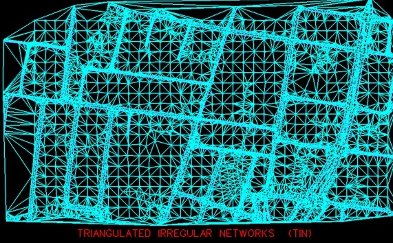
Summary and Final Tasks
Summary
Congratulations! You have just completed Lesson 7. I hope that you appreciated the value of the UAS imagery in producing geospatial data that is suitable for many applications in our day to day life. Ortho photo and digital elevation model are indispensable tools used in many environmental and engineering projects. Without them, we would have to put many boots on the ground to survey the terrain and provide the necessary data for engineering and planning. Practicing with the processing software Pix4D, which I selected for the course, will help you tremendously in appreciating the quality and value of the digital ortho photo and digital elevation model.
Final Tasks
| 1 | Complete the Lesson 7 Quiz. |
|---|---|
| 2 | Work on your final project report and presentation (due next week). |
| 3 | Practice generating DSM and ortho mosaic at different GSDs using Pix4D and evaluate the differences in qualities. |
| 4 | Continue working on your COA Application and the Final Project Report. |
Lesson 8 Civilian and Commercial Applications of the Unmanned Aerial System
Lesson 8 Introduction
Welcome to Lesson 8! In this lesson, you will become familiar with the different applications that the UAS is utilized for. The list of commercial and civilian applications is increasing by the day. It is difficult, if it is not impossible, to nail down such a list. The low cost and easy deployment of the UAS encouraged many people to utilize the unmanned aircraft to replace manned aircraft for their activities. Users are discovering new applications every day; however, we will only cover in this lesson the most obvious one. We will not cover the military application, as it is obvious, but we will consider, for the purpose of this lesson, the security and surveillance use of UAS as a civilian/commercial application since some of such services are offered commercially. Much of the commercial and scientific use of UAS that concerns us is in the field of geospatial data acquisition for remote sensing activities. The term “geospatial data” refers to any dataset that is referenced spatially (i.e., geolocated or geo-referenced) with known coordinates systems and datum. I expect from you in this lesson to read chapter 6 of the textbook Introduction to Unmanned Aircraft Systems and several external readings I will point out in the lesson notes.
Lesson Objectives
At the successful completion of this lesson, you should be able to:
- recognize different applications of the UAS for civilian use;
- understand how the UAS data is used for different applications;
- compose a list of additional applications that can be served by UAS.
Lesson Readings
- Chapter 4 (UAS Sensing: Theory and Practice) of textbook 1, 2nd edition: Barnhart, et al., Introduction to Unmanned Aircraft Systems
- Chapter 20 of textbook 3: Wolf, et al., Elements of Photogrammetry with Applications in GIS
- Gahran, A. “Fighting fire with data, spacecraft, drones [114]"
- Chao, H., et al., "AggieAir: Towards Low-cost Cooperative Multispectral Remote Sensing Using Small Unmanned Aircraft Systems [22]"
- Read the dronenodes.com article Commercial Drone Applications On The Rise | Enerprise UAV Solutions | 2018 [115]
- Read the lecture slides on Digital Image Classification [116]
Lesson Activities
- Watch the webinar: " Applying Drones to Surveying and Engineering Projects Today. [117]"
- Complete Lesson 8 Quiz.
- Submit your results for exercise 2 data processing in Pix4D.
- Submit your COA Application.
Digital Image Classification for Land Use Land Cover Assessment (LCLU)
Digital Image Classification is an information extraction process (machine or automated interpretation) that involves the application of pattern recognition theory to multispectral imagery. It analyzes spectral properties of various surface features (e.g., crops) in a multiband image and sorts spectral data into spectrally related categories by the use of predefined, numerical decision rules.
The process involves:
- Categorizing images into different surface materials or conditions
- Collection of spectral signatures for specific surface materials
- Based upon spectral response
- Assumes unique spectral signatures exist for land covers
- Trains the computer to recognize those spectral signatures
- Statistical operation
- No direct site or situation information
- Does not rely on visual interpretation
- Not necessarily more accurate or objective than visual interpretation
- Someone must decide the classes and whether signatures are accurate or not
- Signature extraction
- Unsupervised classification using statistics or clustering algorithm
- Supervised classification using training sites
- Poor signatures lead to poor results
- Possibly stratify broad classes first
- Classify the imagery
- Spatial filtering for GIS compatibility
- Accuracy assessment
The process utilizes one or more of the following recognition types:
- Spectral pattern recognition: When decision rules are based on spectral radiance characteristics of the scene.
- Spatial pattern recognition: When decision rules are based on geometric characteristics of the scene (i.e. shape, size, patterns)
- Temporal pattern recognition: uses time as an aid in feature identification
- Object-oriented classification: involve combined use of both spectral and spatial recognition
Among the difficulties usually encountered with this technique are the following:
-
- Signature is not unique for given sensor characteristics
- Signature too unique
- Same cover type but with distinct differences
- Soil moisture, surface material, atmospheric conditions
- Same cover type but with distinct differences
- Mixed pixels
- Signature extension issue (over space and time)
There are two types of image classification algorithms, those are:
- Unsupervised Classification: uses an automatic clustering algorithm that analyzes the “unknown” pixels in the database and divide them into several spectrally distinct classes based upon their natural grouping or clusters.
In the unsupervised process, a user directs a computer software package to automatically identify and categorize pixels in an image. This is done on a purely statistical basis, though the user has control over the number of statistical classes, or clusters, to be created. With different classification algorithms, the user will also have control over statistical parameters, such as how much variation is permitted in a single class.
While there are no set rules on how many classes should be defined, a general rule of thumb is that the classes should total three times the number of final land cover categories sought. This allows for the possibility of different spectral signatures pertaining to the same land cover type (for example, if forest is sought as a class, deciduous and coniferous forests may require more than one spectral signature to accurately categorize them as forest). A number of these classes will likely represent meaningless categories or mixed pixels that may then be thrown out at a later point in the process.
Once a set of signatures has been defined, they may then be used to classify the entire image. Pixels with statistical characteristics similar to those in the signature set will be assigned the appropriate class. The resulting thematic layer has every pixel assigned a value representing the signature it was determined to be best represented by, Figure 8.1. This data set is then evaluated by the user to determine what land cover type is represented.
Processing Steps:
a - clustering or grouping
b – coloring
c – identification
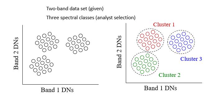
Advantages and Disadvantages of Unsupervised Classification
Pros:
+ no extensive prior knowledge of the region required
+ opportunities for human error minimized
+ unique classes are recognized as distinct units
+ logistically less cumbersome
Cons:
- natural groupings do not necessarily correspond nicely with desired information classes
- no control over the menu of classes and their specific id
- spectral properties of informational classes vary over time, relationships between information and spectral classes change - make it difficult to compare unsupervised
classes from one image/date to another
- Supervised Classification: The process of using samples of known informational classes (training sets) to classify pixels of unknown identity. Identification and delineation of training areas is key to successful implementation. The basic strategy in using supervised classification is to sample areas of known cover types to determine representative spectral values of each cover type. Such samples are called training areas or training fields, Figure Training fields or spectral signatures are established from homogeneous cover type areas through:
- Map digitizing - transfer photo information to base map (use table digitizer)
- On-screen digitizing, Figure 8.2
- Seed-pixel approach
The main steps in supervised classification are the following:
- Training Class Selection
- Generation of statistical parameters to train the classification algorithm, such as:
- class means
- standard deviations
- covariance matrices
- correlation matrices
- Data Classification: Assigning each pixel of the data to one of the training class
- Evaluation and Refinement
- Documentation: Maps and tabular summaries
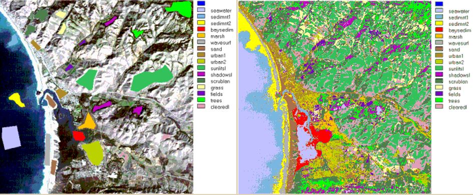
Figure 8.2 Left: Training samples Right: Supervised Classification on an image
Additional Remarks:
- With supervised classification, the process relies on user input to identify areas of specific cover types and to apply a classification algorithm that then utilizes that information to find the same cover type in other regions of the image. This process often involves having specific information on ground conditions collected through fieldwork or through high-resolution imagery/aerial photography. The sites of interest are referred to as training or calibration sites. Essentially, those portions of the image that will be used to identify other portions of the image with similar characteristics. A second set of “known” sites may be reserved for use in accuracy assessment. These are often referred to as calibration or truth sites.
- Statistics for training sites are used to define a spectral signature for specific cover types of interest. A range of supervised classification processes exist but the Maximum Likelihood classifier is one of the most common.
- Each pixel in an image is compared to the statistics compiled for the different signatures. The classification algorithm determines on a probability basis the likelihood that any given pixel should be assigned to any given class. The class providing the highest likelihood is the one that the pixel is assigned to.
Good Strategy for Supervised Classification
- Number of pixels - want to statistically characterize the spectral properties of an informational class (i.e. forest, crop, water), should have >= 100 pixels total for an informational class
- Location - geographically dispersed, boundaries away from edge/mixed pixels number of areas - depends on the number of information categories, 10 at a minimum, enough for accuracy assessment and incorporation of spectral subclasses
- Uniformity - unimodal distributions, use training areas to characterize mean, variance, covariances - sometimes not easy due to spectral variation present
Read more on Digital Image Classification [116].
To Read
To Do
- Submit materials for Digital Image Classification
The Different Application of the UAS
In this section, you will become familiar with and understand the different civilian and commercial applications of the UAS as it stands today. UAS applications that concern us the most are the remote sensing applications. Here, the UAS is replacing manned aircraft as an acquisition platform. Remote sensors such cameras and LiDAR systems are shrunk in size and weight to make them more suitable for the lightweight small UAS as was mentioned in the Payload section of Lesson 2. Remote sensing applications derived from sensors onboard a UAS are more or less similar to the applications that one can expect from a manned system. Manned aircraft can carry larger and heavier payload, which open the door for additional applications that required large sensors such as IFSAR. Reported applications for the UAS include the following:
- Remote Sensing Applications
- Precision Agriculture: Precision agriculture is the most widely used civilian application of the UAS. Farmers and the agricultural community are very optimistic about the prospect of using UAS for their daily activities. The following articles should provide you with a fairly decent idea of the topic:
- "A new era in remote sensing of crops with unmanned robots [120]"
- Drones Diversified: Krannert alumnus looks skyward, hoping unmanned vehicles will help produce an agricultural windfall [121]
- Robotic scouting: UAVs in the presentation Robotics for specialty crops: past, present and prospects [122]
- Range Land Management
- Landslides Research: Engineers are using UAS for land monitoring and management [123]. This field is also witnessing a promising future with the use of the UAS for their daily repetitive monitoring activities.
- Ocean and coastal Research
- Contaminant Spills and Pollution
- Landfill Mapping and monitoring
- Engineering and Surveying [117]
- Corridor Mapping
- Mining site mapping
- Crop and aquaculture farm monitoring
- Mineral exploration
- Spectral and thermal analysis
- Critical infrastructure monitoring, including power facilities, ports, and pipelines [124]
- Commercial photography, aerial mapping and charting, and advertising
- Disaster response, including search and support to rescuers, in situations such as:
- fires,
- floods and hurricanes,
- landslides
- Medical Supplies Delivery [125]
- Traffic monitoring, and
- Other environmental control and monitoring.
- Precision Agriculture: Precision agriculture is the most widely used civilian application of the UAS. Farmers and the agricultural community are very optimistic about the prospect of using UAS for their daily activities. The following articles should provide you with a fairly decent idea of the topic:
- General Applications and Services
- media resources
- security awareness
- communications and broadcast, including news/sporting event coverage
- cargo transport
Details on some of these applications are given in chapter 6 of the textbook and assigned readings listed below. Try to visit the UAV Applications [126] in this site, as it has interesting information about different aspects of the UAS and its applications. Another way to explore potential applications of UAS-derived products is to look into the different applications of Geographic Information System (GIS) as they are closely related. In this regard, ESRI published on their website a good educational overview to highlight the different applications of GIS [127].
To Read
- Chapter 6 of Introduction to Unmanned Aircraft Systems
- Chapter 20 of Elements of Photogrammetry with Applications in GIS
To Do
Watch the webinar: "Applying Drones to Surveying and Engineering Projects Today" [117]
UAS for Disaster Response
In this section, you will become familiar with a widely used application of the UAS: the UAS for disaster response.
One of the widely utilized applications for the UAS is for disaster response situations. UAS is particularly useful for tasks that include one or all the 3 Ds -- dirty, dangerous, and dull:
Dirty: is much open to interpretation and to operation environment, but it can be described by flying over oil, nuclear, or gas installation sites where accidents have occurred, such as the Japanese Fukushima Daiichi nuclear plant, to take air samples or imagery.
Dangerous: refers clearly to situations where a pilot in a similar mission could become a casualty due to dangerous operations.
Dull: is when repetitive tasks are required over and over again. An example of the dull mission is border surveillance and maritime patrols that need eyes in the sky for hours at a time.
For UAS to suitably serve disasters, it needs more capabilities besides its adaptation for the 3 D’s factors. Such capabilities are defined by survivability, durability, and adaptability.
Survivability: Survivability of a UAS in a disaster response scenario relies on its efficient system of communications. For a UAS search and rescue mission, the UAS should consider three forms of communications. Those are:
- communication between the UAS operator and the UAS;
- communication between the operator and the victims on the ground;
- communication between other rescue ground machines and their teams.
Durability: The system's ability to survive a harsh or unpredictable operation environment such as unpredictable dropping debris, changing environment and loss of signal. UAS operation designers in such environments usually relay on multi-level UASs. As an example of this is the utilization of a High Altitude Long Endurance (HALE) UAS in the operation to carry equipment, provide a backup communication link, and to provide a high altitude overview of the site to plan emergency exits routes.
Adaptability: The ability of a mini-UAS with its small size to overcome fallen debris and unpredictable narrow spaces while maintaining its ability in sensing changes in an unpredictable and uncertain environment.
As examples of the use of UAS for disaster response, we will single out the UAS use for forest fire disasters.
UAS for Forest Fires:
Remote sensing techniques have proven to be very effective in mapping and monitoring fires and in giving feedback to first responders. Satellite remote sensing has limited capabilities in supporting fire response. This is due to the fact that the most available satellites have limited spatial resolutions (limited details) and they only occasionally orbit over the fire site, while fire monitoring needs continuous (24/7) coverage. However, satellite imagery can be useful in monitoring fires on a regional or national level, but not on a fire-front micro level. Thermal imagery from MODIS sensors on board the Terra and Aqua satellites with a resolution of 1 km were used by the U.S. Department of agriculture Forest Service Active Fire Mapping Program to monitor regional fires across the U.S. Beside the coarse resolution of its imagery, MODIS orbit any location only twice daily, which is infrequent for tracking the evolution of the fire and to support firefighters in real time.
Alternative to satellite imagery, aerial imagery from manned and unmanned aircraft is frequently used to provide needed frequent aerial observations of a fire. Two approaches were utilized in using the UAS for fire monitoring. The first High Altitude Long Endurance system (HALE) UAS can fly high and provide imagery with better resolution and better frequency than satellites. However, HALE UAS is expensive to procure and to maintain.
The second approach uses fleets of small UAS working cooperatively to provide more detailed information on the fire and its perimeter. In some cases, both approaches are utilized together with the HALE providing an overview image of the fire while small UASs are used to transmit high definition imagery in real time for the perimeter areas of the fire.
Here in the U.S., several wildfire monitoring programs have been adopted over the years. An example of such programs is the joint cooperation between NASA, General Atomics Aeronautical Systems, Inc. and various government agencies involved in fire research. The project used the General Atomics ALTUS II UAS, which is the civilian version of the Predator. Among the sensors on board the ULTUS II payload was a thermal multispectral scanner. Imagery was transmitted to the ground station through INMARSAT geostationary satellites. Once the imagery is received at the ground station, it goes through the geo-referencing and ortho-rectification processes, which convert them to a geo-referenced map before it goes into the hands of the field team. NASA published images (Figure 8.3) of the Grass Valley/Slide fire near Lake Arrowhead/Running Springs in the San Bernardino Mountains of Southern California acquired by the thermal-infrared imaging sensors on board NASA's Ikhana unmanned research aircraft. For more information on past NASA collaborative efforts in the field of different applications for UAS, visit UAS Integration in the NAS [128].
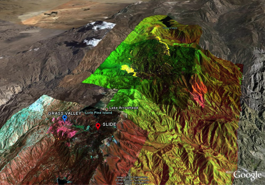
To Read
- CNN article “Fighting fire with data, spacecraft, drones [114]."
- Read the paper "Towards Low-cost Cooperative Multispectral Remote Sensing Using Small Unmanned Aircraft Systems. [22]"
- Read the article Commercial Drone Applications On The Rise | Enterprise UAV Solutions | 2018. [115]
UAS Challenges in Certain Applications
In this section, we will discuss operational challenges in using the UAS for certain applications.
So far, we have read and discussed materials about the successful utilization of the unmanned aircraft for a variety of applications. However, some of such applications are found to be challenging due to different reasons. Among such reasons are the following:
- FAA hesitates in allowing UASs to fly during natural disaster situations such as floods and hurricanes. This is mainly due to the fact that operating a UAS during a storm lacks alternative communications capabilities. During storms, the air traffic control capabilities in the affected area are usually limited, risking the safety of the UAS, which usually operates without sense-and-avoid instruments.
- UAS offers many advantages over conventional of traffic monitoring and transportation planning for police, emergency responders, and DOT. UAS can move from one location to another with higher speed and is not restricted to specific routes that are usually used by ground vehicles. In addition, UAS can fly through hazardous or inclement weather conditions. However, UAS used for traffic monitoring is challenged in urban canyon areas where visibility of the traffic on the ground is obscured by high rise buildings.
- Small UASs cannot maintain their flying routes during stormy conditions. The lightweight of the UAS makes it venerable to gusty winds.
- Here in the U.S., it is difficult to obtain the FAA proper approval to fly civilian projects whenever there are people in the project area, even after the issuance of Part 107. Such restriction is expected to be diminishing in the future as the FAA continues its efforts to integrate the UAS into the NAS.
To Read
- Sections 6.2.2 and 6.2.3 of Chapter 6 of Introduction to Unmanned Aircraft Systems.
Summary and Final Tasks
Summary
Congratulations! You have just finished Lesson 8, Civilian and Commercial Applications of the Unmanned Aerial System. You may notice that the use of UAS for civilian applications extends to almost any applications offered by manned aircraft. In fact, the UAS provides more opportunities than the manned aircraft. The UAS, with its small maneuvering size and its low-cost operation, makes them more useful and more affordable than manned aircraft. That is very true for small projects and projects that may involve hazardous operational conditions. UAS applications are expanding, and we hear about new applications every day. Amazon, for example, recently unveiled plans for UAV package delivery service [130]. What do you think the coolest application is that the UAS should be used for and that no one has thought about until now? Post your opinion in the discussion form.
Final Tasks
| 1 | Complete the Lesson 8 Quiz. |
|---|---|
| 2 | Submit your results for exercise 2 data processing in Pix4D. |
| 3 | Submit your COA Application. |
Lesson 9: Data Quality and Accuracy and Strategy for Selecting a UAS-based Geospatial Mapping System
Lesson 9 Introduction
Lesson 9 Introduction
Welcome to Lesson 9! In this lesson, you will understand and become familiar with the main parameters that need to be considered when selecting a UAS for geospatial business activities. You will also recognize the main manufacturers of UAV, aerial acquisition sensors, and processing software. There are not many materials in the course textbooks that directly deal with these subjects, but one can indirectly derive some information from them. In addition, several research studies were conducted by private or public groups on the status of market and future prediction.
Unmanned Aerial Vehicles (UAVs) are becoming the most dynamic growth sector, and based on a research study conducted by the Teal Group Corporation, it is expected that the global UAV market will top US $54 Billion in the next decade or so.
Lesson Objectives
At the successful completion of this lesson, you should be able to:
- understand the major considerations in selecting a UAS for geospatial business;
- differentiate between the main providers of UAS;
- discriminate between the main providers of aerial sensors for UAS;
- recognize the main providers of software for UAS data processing.
Lesson Readings
- Drone Analyst's "Five Things to Consider when Adopting Drones for Your Business" [131]
Lesson Activities
- Practice with the use of Pix4D software to process the sample data, and produce ortho photo and DSM and submit.
- Prepare your presentation for the final project.
- Submit your final project report.
Basic Considerations for Selecting UAS
Basic Considerations for Selecting UAS
In this section, you will understand the requirements for selecting a UAS. Selecting a UAS depends on many factors that are closely related to the intended use of the UAS. Such use requirements will determine the size and weight of the UAS, and its endurance and range of flight, among other factors. In the following sections, we will briefly discuss each of these factors.
Size and weight
Size and weight a play great role in determining payload size and weight and in limiting its range and endurance. Large UASs have the capability of carrying a larger and heavier payload, including the power source. The larger the UAS, the more fuel or battery power it can carry on board. The more power the UAS can carry on board, the better range and endurance of the UAS.
Range and Endurance
The range of a UAS is an important performance characteristic. It is dependent on a number of basic aircraft parameters and weight of the payload. Maximum UAS range and endurance can be achieved with high propeller efficiency, low fuel consumption, and large onboard fuel (or battery power) capacity. A project that requires long hours in the air will need a larger UAS. However, most UASs that are employed for geospatial mapping purposes now days have an endurance of 90 minutes and a maximum range of around 50 miles.
Stability
In physical mechanics, stability refers to the tendency of an object to stay in its present state of rest or motion despite small disturbances. An aircraft must be stable in order to remain in flight. The forces acting on the aircraft, such as thrust, weight, and aerodynamic forces, have to be in certain directions in order to restore the aircraft to its original equilibrium position after it has been disturbed by a wind or other forces. An aircraft has angular degrees of freedom. Those are rotation around the X-axis or roll, the rotation around the Y-axis, or pitch, and the rotation around the vertical to the ground, or yaw. The aircraft has to remain stable around each of these axes. The most critical rotation is the pitch, and stability about it is called longitudinal stability. Some instability can be tolerated around the roll and the yaw.
Stability is essential for aerial data such as imagery acquisition in order to achieve gap-free imaging results. The use of a gyro-stabilized mount for the camera or the imaging sensor is preferred for mapping missions, as it results in uniform coverage free of gaps.
Cost
UAS costs play a great role in the decision for acquiring one. The price of a large UAS sometime exceeds the price of a typical manned aircraft, such as various models of Cessnas, used for aerial imaging. However, the cost of a UAS is justified by the type of jobs that are expected for the use of the UAS. Smaller UAS-based aerial imaging jobs are only justified through the use of a small UAS that costs under $100,000. It is worth mentioning here that due to strict regulations by the FAA on flying UAS, there are no large jobs for the UAS at the current time within the geospatial mapping community. No one can commercially utilize UASs for money-making projects, therefore only smaller UASs are utilized by the mapping community. Once the FAA eases the regulation, we should expect larger demand for medium or large UAS.
Payload Capacity
The maximum weight that a UAS can carry on board also plays an important role in the decision of UAS selection. Different applications require different sensors and therefore different payload capacities. Current UAS used by the mapping community can carry a payload varying in weight between a few to 100 lbs. The payload capacity directly affects the cost of the UAS, as it limits the range and endurance for the UAS. UAS with longer range and endurance cost more than those that fly a maximum distance of 35 miles and for a period of 60 minutes.
To Read
Read the article "Five Things to Consider when Adopting Drones for Your Business" [131] by Drone Analyst.
To Do
Practice with the use of Pix4D software to process the sample data.
UAS Market Survey
In this section, you will gain an understanding of the different brands and makers of the UAV, payload sensors, and processing software.
Market survey of the Air Vehicle (UAV)
Large UAS that are used mainly for defense purposes are around for a long time and have sophisticated technologies built into them. Examples of the manufacturers of such UAS are AAI Corporation, AeroVironment, Aurora Flight Sciences, BAE Systems, Boeing, Elbit Systems, General Atomics Aeronautical Systems, Inc., Israel Aerospace Industries, Northrop Grumman, Raytheon, Rotax, Sagem, Selex Galileo, and many others. Within the last decade, many startup companies started manufacturing low-cost UAS that are mainly used for civilian purposes. Examples of those manufacturers are Trimble, Altavian, Sensefly Ltd, American Aerospace Advisors, Prioria, Uconsystem, Idetec, and many more.
The following four resources contain good information on existing systems and manufacturers:
- Unmanned Aerial System (UAS) Survey [132]
- GIM International Volume 28 Spring 2014 [124]
- UAS Suppliers [133]
- 24th annual edition of Shephard Media’s "Unmanned Vehicles Handbook" [134]
Market survey of Payload Sensors
The sensors required for UAS that are utilized for mapping purposes are mainly limited to cameras (Visible, near-infrared, and thermal infrared). The second resource provided in the previous section offers a list of sensors manufacturers that are used for UAS payloads. UAS payloads used for the mapping community mainly include imaging cameras. Such cameras have a variety of spectral bands such as visible (Red, green, blue), near infrared (NIR) and thermal infrared. There is only one LiDAR system developed mainly for the UAS and that is the VUX-1 manufactured by Riegl, which was described in Lesson 2. The most obvious provider of digital cameras (without endorsing any of them) that are small enough to fit within UAS payloads are the following:
- Phase One, with their multiple models of aerial cameras [135].
- Imprex, with their latest model of Bobcat cameras [136]
- Nikon, with their multiple models of cameras [137]
- Mecasense with their multiple models of multi-spectral cameras [138] or Parrot for their Sequoia [139] camera
Market survey of Processing Software
For image-based mapping products generation, users will need efficient photogrammetric processing software. Such software should be capable of performing the following operations, among others:
- organizing the input imagery, camera calibration reports, GPS-derived camera position, IMU-derived camera orientation angles, and ground controls data in a simple database;
- having user-friendly graphical user interface (GUI);
- having good data viewers, i.e. orthos and DSM;
- handling tens of thousands of images per project in TIFF or JPEG formats;
- image coverage verification through rapid data processing mode;
- performing automatic aerial triangulation processing using simultaneous bundle block adjustment with viewing and manual editing capability;
- accepting GPS-derived camera position and IMU-derived camera orientation;
- camera self-calibration;
- modeling GPS shift and drift;
- producing quality control reports;
- exporting exterior orientation parameters for photogrammetric work station;
- performing ortho rectification;
- automatic DSM generation through auto-correlation;
- performing image mosaic and capability to edit mosaic lines;
- exporting ortho tiles according to user defined layout in shape file format;
- performing color balancing and radiometric enhancement;
- distributed processing (parallel processing) using computing farm;
- batch processing or scripting.
Among the most obvious data processing software that are optimized for UAS data processing in the market (without endorsing any of them) are the following:
- Agisoft Metashape [140]
- Pix4DMapper [141]
- Menci APS [142]
- CORRELATOR3DTM [143] by SimActive
- Trimble Inpho UASMaster [144]
Each of these five software packages meets most of the capabilities listed above. However, some of them may be more suitable than others, depending on the situation and the nature of the project.
To Do
- Practice more with the use of Pix4D software to process the sample data. Produce ortho photo and DSMm and send me screenshots of the products.
Geospatial Data Accuracy and Quality and Mapping Standards
Geospatial Data Accuracy and Quality and Mapping Standards
Introduction:
Evaluating the quality and accuracy of geospatial data is one of the most important topics among geospatial data users. Geospatial data are used for diverse applications, including engineering and positioning applications. Knowing how accurate the measurements are that are derived from geospatial data is a matter of life or death in some applications, like when locating gas pipelines. In this section, you will be introduced to various statistical concepts that are related to determining geospatial data accuracy. You will also learn about the latest map accuracy standards designed for digital geospatial data published by the American Society of Photogrammetry and Remote Sensing (ASPRS).
Metrics in Geospatial Production Process:
For any geospatial data product, collecting metrics about a dataset revolves around the following questions:
- How well does the map fit a national or a global coordinates system and datum?
- How well does the geometric and radiometric quality meet or depart from the client’s expectations or specifications?
- How well do these metrics fit a “standard” or what is considered standard within the geospatial industry?
Why we are concerned about accuracy?
Errors exist in any product we produce, no matter how accurate the instrument or the process we utilize. This is because all measuring instruments are not perfect, including laser instruments. Figure 1 illustrates the common instruments used in surveying and mapping practices and which we may think are perfect measurement devices.
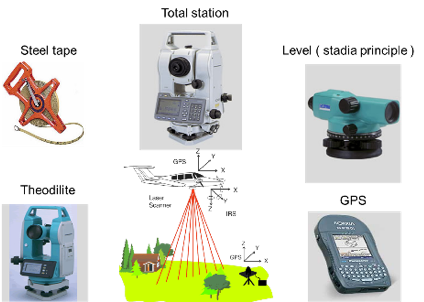
Errors in Measurements
Errors in Measurements
There are two types of errors that concern us the most in geospatial data generation, and those are random error and systematic error. The third type, which is what we call blunders, is not considered an error, but we need to understand it and deal with it appropriately.
Random Error (or accidental error) is the type of error that randomly happens in nature due to our, or the instrument’s, incapability in realizing the true value. The true value in any measurement process is elusive to us and is beyond our metaphysical power. In a measuring process, we are only estimating the true value. Random error can be reduced by training, experience, and improved quality, but it cannot be eliminated.
Systematic Error: Is the error that has a repeated constant value and follows a mathematical logic. It can be reduced through calibration.
Blunders: A blunder is not an error; it is a mistake resulting from carelessness or negligence that resembles error. Common causes of blunders in surveying and mapping are:
- Measurement taken incorrectly
- Values misread from the measuring device (i.e. screen)
- Number transposed as they are recorded (696 vs. 969)
- Miscounting grids ticks
- Handwriting that is hard to read
- Values entered incorrectly into the computer
- Using the wrong datum and/or coordinate system
- Using the wrong units (meter versus US or international foot)
- Rounding numbers in recording the data
Facts on Error and Normal Distribution:
- Errors are unavoidable, but controllable;
- Any mapping process will have some variation of errors built in;
- No combination of machine and human can produce a product that is exactly the same each time;
- Biases should be removed prior to analysis;
- Small errors are more common than large errors;
- Errors are just as likely to be positive as negative;
- Large errors seldom occur and can only be so big. Blunders can be large.
Accuracy Defined
Accuracy Defined
Accuracy: The closeness of results of observations, computations, or estimates of graphic map features to their true value or position on the ground.
Precision (Repeatability): The closeness with which measurements agree with each other.
Facts about Accuracy:
- True value is the theoretically correct or exact value of a quantity. The true value is elusive to us, and it cannot be reached considering our human limitations. True value is a matter relate to metaphysics.
- Accuracy is part of the map metrics that need to be included in the metadata of any geospatial dataset.
To illustrate the concepts of accuracy and precision in a practical fashion, let us consider evaluating the results of the four shooting sessions of Figure 2 that the sharp dart shooter completed at different times. In session A, the shooter’s shots seem to be scattered around the bullseye. He/she managed to get the shots around the targeted spot, or the bullseye, but failed to land them close to each other, i.e. they are scattered apart. To evaluate such a session, we say the shooter was accurate as he/she stayed close to the bullseye, but not precise, as the shots were not close to each other. In session B, we would say the shooter managed to cluster all shots in one spot, so he/she was precise but far away from the bullseye, so he/she was not accurate. Accordingly, in session C, he/she was accurate and precise, while in session D the shooter was neither accurate nor precise. To illustrate the concept of biases in measurements, let us analyze sessions B and C. Assuming the two sessions were shot by the same shooter, it is obvious that the shooter performed perfect shots in both sessions but that his/her shots in session B were biased due to mechanical misalignment of the bow or the gun, if a gun was used. Such misalignment of the bow, the gun barrel, or the sight scope caused the shots to be systematically directed to the wrong position instead of the bullseye, causing a bias in the shots. Once proper calibration is made to these mechanical defects, the bias is then removed and all the shots will perfectly fall around the bullseye, like in session C.
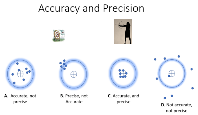
To evaluate the shooter results using probability and density distribution terms, the results of session B are equivalent to the random distribution 3 of Figure 3, precise but not accurate, assuming the most probable value of the bullseye is represented by p on the x-axis. The results of session A, however, resemble the distribution 2 of Figure 3, accurate but not precise. For more information on the subject, please watch this NGS video [145].
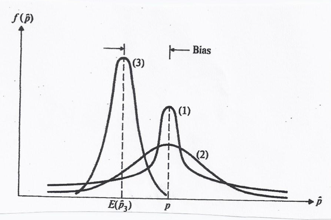
The Ever-confusing Statistical Terms
The Ever-confusing Statistical Terms
To illustrate the different statistical terms we usually run into when we discuss data accuracy, let us consider the five error values (3-in., 2-in, 1-in., 5-in., and 4-in.) that were calculated on a population of data.
- Mean (average)
- Range = the distance between the largest error and the smallest error, i.e. Smallest = 1, Largest = 5 3)
- Variance = measure of spread or dispersion around the mean. It is the mean square of all the errors
Here, inch2 is a meaningless unit and a better statistical term to use is the standard deviation. - Standard deviation, also called one-sigma, is the square root of the variance =
- Root Mean Square Error (RMSE)
- RMSE is not Standard deviation or sigma; they are different.
- Root Mean Square Error (RMSE) is computed as follows:
Where,
Z = Measured Value from the data
Zi = Control Value (field surveyed)
n = number of measurements
Relationship Between Standard Deviation and Root Mean Square Error (RMSE)
Relationship Between Standard Deviation and Root Mean Square Error (RMSE)
Facts about RMSE:
- Includes random and systematic errors
- More useful to use as it reveals biases (systematic error)
- It tells us how accurate the data is
Facts about Standard Deviation:
- Includes only random error
- Reflects only how precise the data is
- It does not tell us how accurate the data is in the presence of biases. It only tells us how precise the data is.
Table 1 illustrates the difference between standard deviation and the RMSE in revealing the presence of biases in measurements. The table represents a vertical accuracy evaluation for points cloud derived from UAS imagery by comparing it to a higher accuracy elevation model derived from a mobile lidar mapping system. The UAS-derived elevation model needed to meet 5-cm (0.164-ft) accuracy. If we used standard deviation alone, the data would meet the specifications with a value of 0.076-ft. However, looking at the high value of 0.246-ft. (7.5-cm) of the mean, it is obvious this data set contains a bias and the only way to catch it is by either evaluating the value of the mean or using the RMSE as the accuracy measure. The high value of the RMSE = 0.257-ft. (7.83-cm) will flag the data as not meeting specifications. The far right column contains the error values after removing the bias of 0.246-ft. (7.5-cm) from the measurements. Once we remove the bias, the values for the RMSE and the standard deviation are equal and they both meet the project accuracy specifications. Removing a bias from elevation data could be as simple as shifting the entire dataset up or down by the magnitude of the bias itself, such practice is called z-pump.
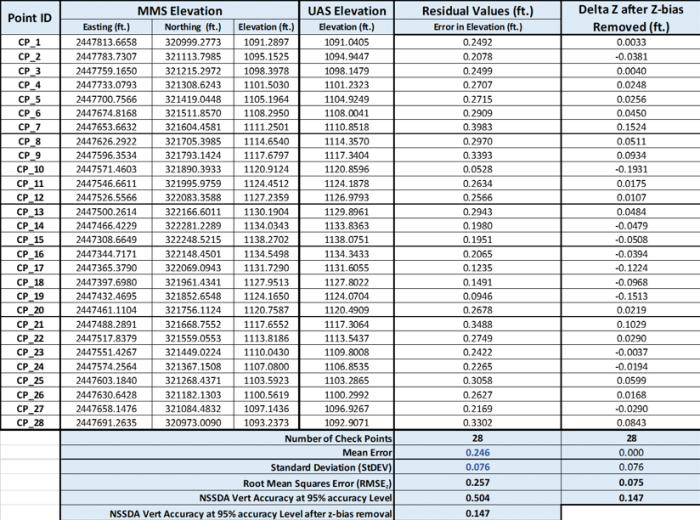
Normal Distribution Curve
Normal Distribution Curve
In randomly distributed repeated measurements, measurements values will vary around the mean or the average, with most values being closer to the average. Deviation from such behavior indicates the presence of bias(es) or perhaps blunders in the measurements. Figure 4 shows a true random distribution of a set of measurements that do not contain biases. For the measurement’s distribution in Figure 4, we notice that 68.2% of the measured values fall within +/- 1 RMSE or +/- 1 sigma from the mean value, that is 34.1% on both sides of the mean. We also notice that 95% of the measurements fall within +/- 2 RMSE or +/- 2 sigma from the mean. Understanding such distribution is essential to understanding the map accuracy standard we are going to discuss in the following sections.
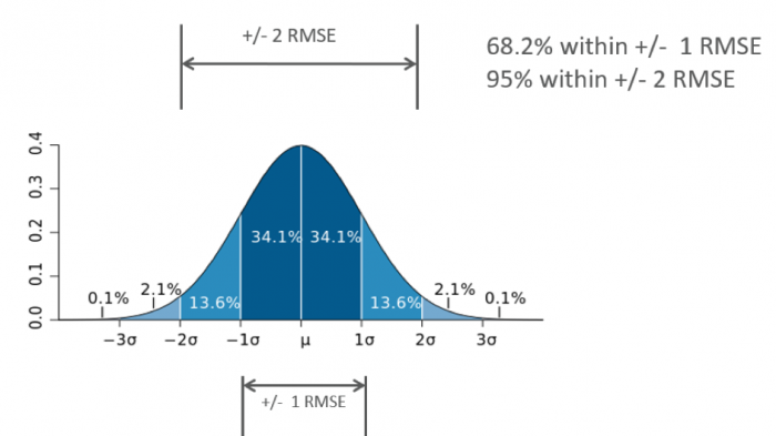
Common Error Estimation Terms
Common Error Estimation Terms
Table 2 lists the most common terms used to estimate errors in surveying and mapping. Probable error is the term used to describe the probability, or the confidence level, that 50% of the errors fall within, while 95% errors represents the confidence level that 95% of the measured errors values fall under.
| Error | % Error | Constant wrt |
|---|---|---|
| Probable Error | 50 | 0.6745 σ |
| Standard Error | 68.27 | 1.000 σ |
| 90% Error | 90 | 1.6449 σ |
| 95% Error | 95 | 1.9599 σ |
| 3σ Error | 99.73 | 3.0000 σ |
Positional Errors and Accuracy
Positional Errors and Accuracy
According to the ASPRS Positional Accuracy Standards for Digital Geospatial Data, the terms positional error and absolute and relative accuracy are defined as follow:
- Positional error – The difference between data set coordinate values and coordinate values from an independent source of higher accuracy for identical points.
- Positional accuracy – The accuracy of the position of features, including horizontal and vertical positions, with respect to a horizontal and vertical datum.
- Relative accuracy – A measure of variation in point-to-point accuracy in a data set.
- Relative accuracy – Characterizes the internal geometric quality of an elevation data set without regard to surveyed ground control.
The New ASPRS Positional Accuracy Standards for Digital Geospatial Data
The New ASPRS Positional Accuracy Standards for Digital Geospatial Data
In November of 2014, the American Society of Photogrammetry and Remote Sensing (ASPRS) published Edition 1 of the first ever mapping accuracy standards that are solely designed for today's digital geospatial data. Edition 2 was published on August 23, 2023 to correct some measures to suite today's technologies and processes and add six addenda on best practices and guidelines.
Motivation Behind the New Standard is:
-
Legacy map accuracy standards, such as the ASPRS 1990 standard and the National Map Accuracy Standards (NMAS) of 1947, are outdated (over 30 years since ASPRS 1990 was written).
-
Many of the data acquisition and mapping technologies that these standards were based on are no longer used.
-
More recent advances in mapping technologies can now produce better quality and higher accuracy geospatial products and maps.
-
Legacy map accuracy standards were designed to deal with plotted or drawn maps as the only medium to represent geospatial data.
-
Within the past two decades (during the transition period between the hardcopy and softcopy mapping environments), most standard measures for relating GSD and map scale to the final mapping accuracy were inherited from photogrammetric practices using scanned film.
-
New mapping processes and methodologies have become much more sophisticated with advances in technology and advances in our knowledge of mapping processes and mathematical modeling.
-
Mapping accuracy can no longer be associated with camera geometry and flying altitude alone (focal length, xp, yp, B/H ratio, etc.).
- New map accuracy is influenced by many factors such as:
- the quality of camera calibration parameters;
- quality and size of a Charged Coupled Device (CCD) used in the digital camera CCD array;
- amount of imagery overlaps;
- quality of parallax determination or photo measurements;
- quality of the GPS signal;
- quality and density of ground controls;
- quality of the aerial triangulation solution;
- capability of the processing software to handle GPS drift and shift;
- capability of the processing software to handle camera self-calibration,
- the digital terrain model used for the production of orthoimagery.
These factors can vary widely from project to project, depending on the sensor used and the specific methodology. For these reasons, existing accuracy measures based on map scale, film scale, GSD, c-factor and scanning resolution no longer apply to current geospatial mapping practices.
- Elevation products from the new technologies and active sensors such as lidar, UAS, and IFSAR are not considered by the legacy mapping standards. New accuracy standards are needed to address elevation products derived from these technologies.
The New Standard Highlights
- Sensor agnostic, data driven: Positional Accuracy Thresholds which are independent of published GSD, map scale or contour interval
- It is All Metric!
- Unlimited Horizontal Accuracy Classes:
- Added additional Accuracy Measures
- Aerial triangulation accuracy,
- Ground controls accuracy,
- Orthoimagery seam lines accuracy,
- Lidar relative swath-to-swath accuracy,
- Recommended minimum Nominal Pulse Density (NPD)
- Horizontal accuracy of elevation data,
- Delineation of low confidence areas for elevation data
- Required number and spatial distribution of QA/QC check points based on project area
- Added six addenda on best practices and guidelines for:
1) General Best Practices and Guidelines
2) Field Surveying of Ground Control and Checkpoints
3) Mapping with Photogrammetry
4) Mapping with Lidar
5) Mapping with UAS
6) Mapping with Oblique Imagery
Advantage of Specifying the New ASPRS Positional Accuracy Standards for Digital Geospatial Data for a Project
Users of the new standards do not have to specify accuracy details for the intermediate processes in products generation. The user needs to specify the final deliverable product accuracy and the new standards will set up all accuracy specifications for intermediate processes, such as ground survey, aerial triangulation, etc., involved in the production of the final product. Figure 5 illustrates such a concept.

Horizontal Accuracy Standards for Geospatial Data
Some of the highlights of the new ASPRS Horizontal Accuracy Standards for Geospatial Data are the following:
- Unlimited horizontal accuracy classes:
The new standard was designed to fit any horizontal accuracy requirement no matter what technology, current or future, is used. Table 3 represents the new ASPRS horizontal accuracy classes.Table 3 The new ASPRS horizontal accuracy classes Horizontal Accuracy Class Absolute Accuracy
RMSEH (cm)
Orthoimagery Mosaic Seamline Mismatch (cm) #-cm R M S E H = R M S E x 2 + R M S E y 2 RMS E H = R a d i a l R M S E = C i r c u l a r R MS E = T w o − d i m e n s i o n a l R M S E o f X & Y - Aerial triangulation results should be twice as accurate as the generated products:
- Ortho and planimetric maps ONLY:
R M S E H ( A T ) = ½ * R M S E H ( M a p ) and R M S EV ( A T ) = R M S E H ( M a p ) - For ortho, planimetric maps, and elevation maps: R M S E H ( A T ) = ½ * R M S E H ( M a p ) and R M S EV ( A T ) = R M S E H (DEM )
- Ortho and planimetric maps ONLY:
- Control points for aerial triangulation should be twice as accurate as aerial triangulation:
- For ortho and planimetric maps ONLY: R M S E H ( GCP ) = ½ * R M S E H ( M a p ) and R M S EV ( GCP ) = R M S E H ( M a p )
- For ortho/planimetric maps and elevation maps: R M S E H ( GCP ) = ½ * R M S E H ( M a p) and R M S EV (GCP ) = ½ * R M S E V (DEM )
- For ortho and planimetric maps ONLY: R M S E H ( GCP ) = ½ * R M S E H ( M a p ) and R M S EV ( GCP ) = R M S E H ( M a p )
Table 4 lists common horizontal accuracy classes for geospatial mapping products.
| Horizontal Accuracy Class RMSEx and RMSEy (cm) | RMSEr (cm) | Orthoimage Mosaic Seamline Maximum Mismatch (cm) |
|---|---|---|
| 0.63 | 0.9 | 1.3 |
| 1.25 | 1.8 | 2.5 |
| 2.50 | 3.5 | 5.0 |
| 5.00 | 7.1 | 10.0 |
| 7.50 | 10.6 | 15.0 |
| 10.00 | 14.1 | 20.0 |
| 12.50 | 17.7 | 25.0 |
| 15.00 | 21.2 | 30.0 |
| 17.50 | 24.7 | 35.0 |
| 20.00 | 28.3 | 40.0 |
| 22.50 | 31.8 | 45.0 |
| 25.00 | 35.4 | 50.0 |
| 27.50 | 38.9 | 55.0 |
| 30.00 | 42.4 | 60.0 |
| 45.00 | 63.6 | 90.0 |
| 60.00 | 84.9 | 120.0 |
| 75.00 | 106.1 | 150.0 |
| 100.00 | 141.4 | 200.0 |
| 150.00 | 212.1 | 300.0 |
| 200.00 | 282.8 | 400.00 |
| 250.00 | 353.6 | 500.0 |
| 300.00 | 424.3 | 600.0 |
| 500.00 | 707.1 | 1000.0 |
| 1000.00 | 1414.2 | 2000.0 |
Vertical Accuracy Standards for Geospatial Data
Some of the highlights of the new ASPRS Vertical Accuracy Standards for Geospatial Data are the following:
- Unlimited horizontal accuracy classes: The new standard was designed to fit any vertical accuracy requirement no matter what technology, current or future, is used. Table 5 represents the new ASPRS vertical accuracy classes.
 Table 5 The new ASPRS vertical accuracy classesClick for a text description of Table 5.
 - The standards introduced two vertical accuracy types, those are:
- Non-vegetated Vertical Accuracy (NVA) for any part of the project that is not covered by vegetation.
- Vegetated Vertical Accuracy (VVA) for the part of the project that is partly or fully covered by vegetation.
- The standards introduced relative accuracy for elevation data beside the absolute accuracy.
Table 6 lists a new accuracy term, which is the relative accuracy. It is mainly addressing the Lidar-derived elevation data. The table also also provides vertical accuracy examples and other quality criteria for ten common vertical accuracy classes

Table 6 Vertical Accuracy/Quality Examples for Digital Elevation Data
4. The standards introduced horizontal accuracy estimation for elevation data
- For Photogrammetric elevation data: the horizontal accuracy equates to the horizontal accuracy class that would apply to planimetric data or digital orthoimagery produced from the same source imagery, using the same aerial triangulation/INS solution.
- For Lidar elevation data: use the following formula:

Table 7 lists some horizontal accuracy values for lidar data based on the previous formula (the GNSS horizontal accuracy is assumed to be equal to 0.10 m, the IMU error is assumed to be 10.0 arc-seconds for the roll and pitch and 15.0 arc-seconds for the heading)

5. The Standards Introduced a Formal Accuracy Testing Statement:
For the first time, the new standards provide users with formal data evaluation statements to be used by the data users and data producers. The following statement are examples of the accuracy statement of an elevation dataset:
5.1 Accuracy Reporting by Data User or Consultant
This type of reporting should only be based on a set of independent checkpoints. The positional accuracy of digital orthoimagery, planimetric data, and elevation data products shall be reported in the metadata in one of the manners listed below. For projects with NVA and VVA requirements, two three-dimensional positional accuracy values should be reported based on the use of NVA and VVA, respectively.
5.1.1 Accuracy Testing Meets ASPRS Standard Requirements
If testing is performed using a minimum of thirty (30) checkpoints, accuracy assessment results should be reported in the form of the following statements:
-
- Reporting Horizontal Positional Accuracy
“This data set was tested to meet ASPRS Positional Accuracy Standards for Digital Geospatial Data, Edition 2 (2023) for a __(cm) RMSEH horizontal positional accuracy class. The tested horizontal positional accuracy was found to be RMSEH = __(cm)”.
-
- Reporting Vertical Positional Accuracy
“This data set was tested to meet ASPRS Positional Accuracy Standards for Digital Geospatial Data, Edition 2 (2023) for a __(cm) RMSEV Vertical Accuracy Class. NVA accuracy was found to be RMSEV = __(cm).” VVA accuracy was found to be RMSEV = __(cm).”
-
- Reporting Three-Dimensional Positional Accuracy
“This data set was tested to meet ASPRS Positional Accuracy Standards for Digital Geospatial Data, Edition 2 (2023) for a ___ (cm) RMSE3D three-dimensional positional accuracy class. The tested three-dimensional accuracy was found to be RMSE3D = ___(cm).”
5.1.2 Accuracy Testing Does Not Meet ASPRS Standard Requirements
If testing is performed using fewer than thirty (30) checkpoints, accuracy assessment results should be reported in the form of the following statements:
-
- Reporting Horizontal Positional Accuracy
“This data set was tested as required by ASPRS Positional Accuracy Standards for Digital Geospatial Data, Edition 2 (2023). Although the Standards call for a minimum of thirty (30) checkpoints, this test was performed using ONLY __ checkpoints. This data set was produced to meet a ___(cm) RMSEH horizontal positional accuracy class. The tested horizontal positional accuracy was found to be RMSEH = ___(cm) using the reduced number of checkpoints.”
-
- Reporting Vertical Positional Accuracy
“This data set was tested as required by ASPRS Positional Accuracy Standards for Digital Geospatial Data, Edition 2 (2023). Although the Standards call for a minimum of thirty (30) checkpoints, this test was performed using ONLY __ checkpoints. This data set was produced to meet a ___(cm) RMSEV vertical positional accuracy class. The tested vertical positional accuracy was found to be RMSEV = ___(cm) using the reduced number of checkpoints.”
-
- Reporting Three-Dimensional Positional Accuracy
“This data set was tested as required by ASPRS Positional Accuracy Standards for Digital Geospatial Data, Edition 2 (2023). Although the Standards call for a minimum of thirty (30) checkpoints, this test was performed using ONLY __ checkpoints. This data set was produced to meet a ___(cm) RMSE3D three-dimensional positional accuracy class. The tested three-dimensional positional accuracy was found to be RMSE3D = ___(cm) using the reduced number of checkpoints.”
5.2 Accuracy Reporting by Data Producer
In most cases, data producers do not have access to independent checkpoints to assess product accuracy. If rigorous testing is not performed by the data producer due to the absence of independent checkpoints, accuracy statements should specify that the data was “produced to meet” a stated accuracy. This “produced to meet’’ statement is equivalent to the “compiled to meet” statement used by prior Standards when referring to cartographic maps. The “produced to meet’’ statement is appropriate for data producers who employ mature technologies, and who follow best practices and guidelines through established and documented procedures during project design, data processing and quality control. However, if enough independent checkpoints are available to the data producer to assess product accuracy, it will do no harm to report the accuracy using the statement provided in section 4.1 above.
If not enough checkpoints are available, but the data producer has demonstrated that they are able to produce repeatable, reliable results and thus able to guarantee the produced-to-meet accuracy, they may report product accuracy in the form of the following statements:
-
- Reporting Horizontal Positional Accuracy
“This data set was produced to meet ASPRS Positional Accuracy Standards for Digital Geospatial Data, Edition 2 (2023) for a __(cm) RMSEH horizontal positional accuracy class.
-
- Reporting Vertical Positional Accuracy
“This data set was produced to meet ASPRS Positional Accuracy Standards for Digital Geospatial Data, Edition 2 (2023) for a __(cm) RMSEV vertical accuracy class.
-
- Reporting Three-Dimensional Positional Accuracy
“This data set was produced to meet ASPRS Positional Accuracy Standards for Digital Geospatial Data, Edition 2 (2023) for a ___ (cm) RMSE3D three-dimensional positional accuracy class
6. The Standards Introduced a new accuracy term, the Three-Dimensional Positional Accuracy:
The following formula defines the three-dimensional accuracy standard for any three-dimensional digital data as a combination of horizontal and vertical radial error. RMSE3D is derived from the horizontal and vertical components of error according to the following formula:

7. The Standards Introduced a new approach for assessing product accuracy by factoring in the accuracy of the surveyed check points when computing product accuracy:
As we are producing more accurate products, errors in surveying techniques of the checkpoints used to assess product accuracy, although it is small, can no longer be neglected and it should be represented in computing the product accuracy. Currently, we quantify products accuracy ignoring the errors in the surveyed check points. In such practice, our surveying techniques approximates the datum, i.e., producing pseudo datum and therefore, we are evaluating the closeness of data to the pseudo datum and not the true datum. The following figure illustrates the current practices and the new one proposed in Edition 2 of the ASPRS standards.

Figure 6 Factoring in the accuracy of the surveyed check points when computing product accuracy
Best Practices in Determining Product Accuracy*
- Check data should not be used in calibrating the tested products:
- Totally independent check points
- Check data must be more accurate than tested data:
- Two times more accurate
- Check data must be well distributed around the project area:
- Check data must be a valid statistical sample:
- Minimum of 30 check points for orthos
- Minimum of 30 check points for elevation data
* according to the ASPRS Positional Accuracy Standards for Digital Geospatial Data, Edition 2 of 2023 (https://publicdocuments.asprs.org/PositionalAccuracyStd-Ed2-V1 [146])
The new ASPRs Standards and number of check points
The new ASPRs Standards and number of check points
The new standards provide Table 8 for the recommended number of check points required for validating product accuracies. For project areas that are larger than 10,000 square kilometers, use only 120 checkpoints.

Table 8 Recommended number of check points required for validating product accuracies according to ASPRS Standards, Edition 2
Find more information about the new ASPRS standards here [147].
Summary and Final Tasks
Summary
Congratulations! You have just completed Lesson 9. You may have noticed from the different sections of the lessons that the UAS market is growing rapidly. There are quite a few manufacturers for the civilian UAS, as well as software and sensor producers. User requirements will drive the selection process for the UAS and the processing software that is right for the job. Required UAS endurance, range and payload capacity will be different from one application to another. However, most applications will prefer more endurance, longer range, and heavier payload if the price is right.
In this lesson, you also learned about the value of evaluating data quality and accuracy and how to use the new ASPRS standards to report such quality and accuracy factors.
By now, you must be finishing the products generation of ortho photo and digital elevation model using Pix4D and the sample imagery. Samples of the products need to be submitted with your project report and presented next week during your presentation.
Final Tasks
| 1 | Prepare your presentation for the final project. |
|---|---|
| 2 | Final Project Milestone: Submit final project report. |
Lesson 10: UAS Safety and Privacy Concerns
Privacy Concerns
Some American citizens, including lawmakers, believe that before Unmanned Aerial Vehicles (UAVs) start routinely observing Americans from above, the Federal Aviation Administration (FAA) needs to address two little concerns, safety, and privacy. The issue of privacy was received differently depending on who is involved in evaluating the UAS impact. Many of us believe that flying a UAS with a camera is no different from flying a helicopter during a mapping mission. However, others see it as clear invasion of their personal privacy, and they want the FAA to curb the use of the UAS in overpopulated areas. During 2013, the Senate Judiciary Committees held a hearing on UAV/UAS issue, where it was very clear that senators in both parties are worried about the threat to Americans’ privacy posed by increasing use of the unmanned aerial systems (UASs). The article "Lawmakers voice concerns on drone privacy questions [149]" published by NBC details the outcome of the discussions occurred during that hearing.
Safety and Security Concerns
Integrating small UAS into the NAS raises concerns as unmanned airplanes pose risk by potential air collision with other airplanes or by causing properties damage or loss of life on the ground. Many people and lawmakers also have concerns about their security, as they believe that drones can be hacked and used for terrorist acts. The report "Unmanned Aerial Vehicles: Examining the Safety, Security, Privacy and Regulatory Issues of Integration into U.S. Airspace [150]" provides fairly good details on the issues of UAS privacy, security, and safety.
PART 107 The Good News
The burden of concerns over privacy was lessened with the issuing of PART 107 by the FAA, as it contained no clause to regulate the use of UAS as it relates to privacy. It was the right move by the FAA as the topic is controversial and there is no easy solution for it. However, things may change in the future as the "FAA Reauthorization Act of 2018 [151]" which was authorized by Congress during its 115th session on April 13, 2018 brought back the privacy issues to the table by mandating the FAA to carry out a review to identify any potential reduction of privacy specifically caused by the integration of unmanned aircraft systems into the national airspace system.
Activities
UAS is capable of collecting very high definition/resolution imagery of people's backyards and perhaps through windows. The public in the United States expressed two main opinions about allowing UAS to fly over populated areas, especially if it is used for surveillance and search and rescue missions.
Discussion Forum
- Review the article "Concerns Over Drone Aircraft Used in the United States; Safety and Privacy Still Concerns, GAO Reports [152]" that discusses the privacy and safety issues of using UAS.
- Read the report "Unmanned Aerial Vehicles: Examining the Safety, Security, Privacy and Regulatory Issues of Integration into U.S. Airspace [150]"
Express your opinion on the two following public stances:
- "The main threat to personal privacy posed by the ever-expanding use of UAVs in U.S. airspace is the substantial potential for violations of the protection against unreasonable search and seizure ensured by the Fourth Amendment to the Constitution." therefore, we should limit or prevent the use of UAS for such purposes.
- Using UAS for such purposes should be allowed, as it is no different from allowing low-flying helicopters on an imagery acquisition mission overpopulated areas or having someone in a neighborhood carrying high resolving power pair of binoculars.
Post to the discussion board and respond to at least one posting from your peers.
- Read the article "Implications of Drones on American Privacy and Freedom" [153] by Mike Tully.
- Complete the comprehensive Quiz.
- Complete the course SEEQ (Student Educational Experience Questionnaire).
- Deactivate\log off your Pix4D license.
- Present your final project.