Lesson 2: Unmanned Aerial System Elements
Lesson 2 Introduction
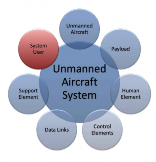
Welcome to Lesson 2! In this lesson, you will become familiar with the elements that combine to create an operational Unmanned Aerial System (UAS). Most UASs consist of an Unmanned Aerial Vehicle (UAV), human elements, payload, control elements (for a larger system it will be a ground control station (GCS) or mission planning and control station (MPCS)), and a data link communication unit (Figure 2.1). Military versions of the UAS will have an additional weapon system platform and supporting soldiers as part of the human element.
In addition, you will understand and develop knowledge about the different acquisition and auxiliary aerial sensors that are usually carried on board the UAS payload. Finally, at the end of this lesson, you will have a working knowledge of the different components forming a UAS and how the different components relate and interact with one another, the data acquisition sensors, and the auxiliary sensors that accompany a UAS mission, such as GPS and IMU.
Lesson Objectives
At the successful completion of this lesson, you should be able to:
- describe and identify the different elements of an Unmanned Aerial System (UAS);
- understand the functionality of each element making the UAS;
- explain how the different elements of a UAS complement each other;
- understand the basics in regard to an aerial vehicle design;
- describe different payloads;
- identify the different miniaturized sensors used for remote sensing;
- understand the fundamentals of digital cameras and LiDAR;
- understand the basics principals of GPS and IMU.
Lesson Readings
- Sections 3.1, 3.2, 3.3, 3.4, 3.5, and 3.6 of chapter 3 of textbook 1: Bankhart et al., Introduction to the Unmanned Aircraft Systems
- Chapter II from Crouch, C. thesis, “Integration of mini-UAVS at the tactical operations level: Implications of operations, implementation, and information sharing. [1]”
- Section 2.6 of the report "Eyes of the Army, U.S. Army Roadmap for Unmanned Aircraft Systems 2010-2035 [2]."
- Chapter 13 of textbook 2: Fahlstrom, et al., Introduction to UAV Systems (Aerospace Series)
- Chapter 9 of textbook 2: Fahlstrom, et al., Introduction to UAV Systems (Aerospace Series)
- Chao, H. et al., "Towards Low-cost Cooperative Multispectral Remote Sensing Using Small Unmanned Aircraft Systems [3]"
- Chapter 10, 11, and 12 of textbook 2: Fahlstrom, et al., Introduction to UAV Systems (Aerospace Series)
- Chapter 17 of textbook 2: Fahlstrom, et al., Introduction to UAV Systems (Aerospace Series)
- Williams, K., Human Factors Implications of Unmanned Aircraft Accidents: Flight-Control Problems [4], FAA report
- Takanmaki, I, et al., "How and why Unmanned Aircraft Vehicles can improve Real-time awareness? [5]"
Lesson Activities
- Complete the Discussion Forum for Lesson 2: SWOT Analysis
- Take the Lesson 1 and 2 quizzes
The Air Vehicle
The air vehicle is the airborne part of the system. The air vehicle here means the aircraft, in conjunction with the payload, that forms an Unmanned Aerial System (UAS). In general, the unmanned aircraft is usually called an Unmanned Aerial Vehicle (UAV) and can be either a fixed-wing or rotary airplane that flies without a human on board.
The UAV is a complicated system including structures, aerodynamic elements such as wings and control surfaces, propulsion systems, control systems, communication elements, and launch and recovery subsystems. Larger UAVs use fuel-powered engines in order to attain flight, while smaller UAVs typically use either gasoline-powered engines or electrically powered engines. When the UAV has sensors and payloads, it is customarily called an Unmanned Aerial System (UAS). In this course, the terms UAS and UAV will be used interchangeably to mean the same. Due to inclusion of the word "unmanned," there has been some resistance in recent years to use of the names Unmanned Aircraft and Unmanned Aerial Vehicle. There is a push to adopt the term Remotely Piloted Aircraft (RPA) or Remotely Piloted Vehicle (RPV) because of the crucial human involvement related to the operation of the system. UAVs come in all different sizes and shapes; however, the following are the major factors to be considered in designing a UAV:
- take-off weight
- wing span
- length
- endurance speed
- endurance time
- weight of fuel
- engine power
- engine capacity
- engine weight
- airframe weight
To Read
- Sections 3.1 and 3.2 of chapter 3 of Introduction to the Unmanned Aircraft Systems
- Chapter II from: Collier C. Crouch, 2005, “Integration of mini-UAVS at the tactical operations level: Implications of operations, implementation, and information sharing, [1]” master’s thesis, Naval postgraduate school, Monterey, California.
- Section 2.6 of the report "Eyes of the Army, U.S. Army Roadmap for Unmanned Aircraft Systems 2010-2035. [2]" It is a good reading about UAS definitions.
The Communication Data Link
The term data link is used to describe how commands are communicated back and forth between the ground control system and the autopilot. The data link is a key subsystem for any UAS, as it provides a two-way communication to ensure that missions are executed safely and according to plan. A good data link is illustrated in Figure 2.2:
- The uplink that is illustrated in Figure 2.2, below, operates with a bandwidth of a few kHz and secures sending data to control the UAS flight path and to communicate with the payload;
- The downlink from the UAS to the ground control station uses a low data rate to acknowledge commands and to send status information about the air vehicle, and uses a high data rate (1-10 Mbs) for sending payload sensor data, such as video, down to the ground control station. The downlink signal can also be used to locate and measure the position of the air vehicle (range and azimuth) in reference to the ground antenna and to improve the overall accuracy of target locations measured by the payload sensors.
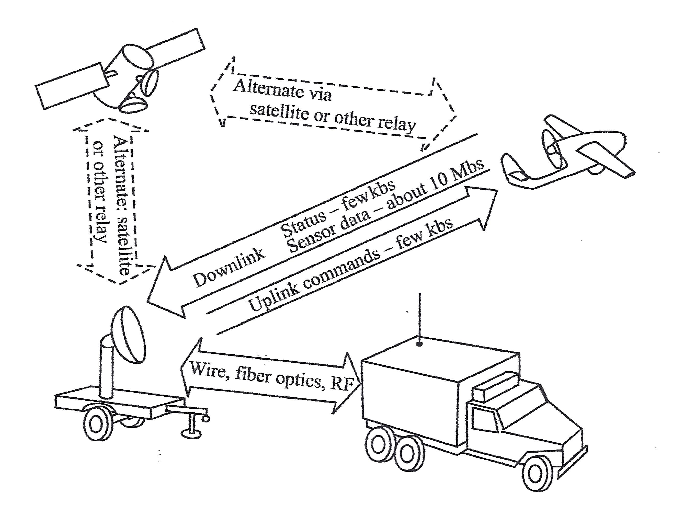
This schematic drawing illustrates the workings of a data link system. The system is composed of four elements:
- the Ground Antenna (which looks like a truck with an antenna extended from the back),
- the Ground Control Station (a satellite dish mounted on an unattached, flat-bed truck trailer),
- the UAS (airborne above the Ground System, which is the Ground Antenna and Ground Control Station together) and
- a Satellite, floating in space.
Between the Ground Antenna and the Ground Control Station is a two-way arrow containing the words "Wire, fiber optics, RF"
An arrow points from the Ground Control Station to the UAS. It contains the words "Uplink commands - few kbs"
An arrow points from the UAS to the Ground Control Station. It contains the words "Status - few kbs; Sensor data - about 10Mbs."
A two-directional arrow between the UAS and the Satellite contains the words "Alternate via satellite or other relay."
A two-directional arrow between the Ground Control Station and the Satellite contains the words "Alternate: satellite or other relay."
There are two different modes for operating a UAS. Those are:
- The radio frequency line of sight (LOS) operation, where a direct communication link is established between the UAS and the ground station, and
- The beyond line of sight (BLOS) operation. This mode of operation is used when the UAS is controlled from far distances beyond the LOS capability. Communications satellites are usually used in this mode of communication.
More details on the two operating modes will be covered in lesson 4.
To Read
- Section 3.4 of chapter 3 of textbook 1 "Introduction to the Unmanned Aircraft Systems"
- Chapter 13 of textbook 2 "Introduction to UAV Systems (Aerospace Series)"
The Command and Control Element
The command and control element is the nerve center for the UAS operation. It controls the following tasks:
- launching the vehicle,
- flying the vehicle,
- recovery of the vehicle,
- receiving and processing data from internal sensors of the flight system,
- receiving and processing data from external sensors of the payload,
- controlling the operations of the payload, and
- providing the interfaces between the UAS and the outside world.
The command and control element utilizes several subsystems to accomplish its missions. They are:
- UAV status and controls,
- payload data display and control,
- map displays for mission planning and for monitoring the flight path,
- autopilot to provide the ability for the UAV to execute its mission based on preprogrammed instructions without operator intervention,
- ground terminal for two-way communication with the UAV and the payload,
- computer(s) to:
- provide an interface between the UAV and operator,
- control the data link and the data flow between the UAV and the command and control station,
- perform the navigation functions for the system,
- perform necessary computations for the autopilot and the payload control functions,
- communication links to other organizations for command and control and for dissemination of information gathered by the UAV.
The most important parts of the command and control element are the Autopilot and the ground control station, as described in the following subsections:
Autopilot
Autopilot is the sub-system that enables partial or fully autonomous flight. A UAV can be operated completely by a remote control, where an operator steers the air vehicle all the time, or a UAV can be flown autonomously, where a pre-programmed path is fully executed from takeoff to landing by the autopilot sub-system without any pilot intervention. Small, light-weight autopilots are readily available and are made by a few manufacturers. Besides guiding the air vehicle throughout the pre-set flight path, the autopilot also executes a “lost link” routine if the UAV loses contact with the ground control station. The lost link procedure guides the UAV to a known waypoint, where contact with the ground control station can again be established. The following scenario was developed for a typical emergency procedure based on loss of link between the Yamaha RMAX UAS and the ground Control Station:
Emergency Procedures for Yamaha RMAX UAS
The RMAX utilizes a redundant communication system to ensure constant contact between the aircraft and the remote pilot. The ground control station provides real-time data regarding aircraft location, altitude and flight characteristics. The pilot constantly monitors the flight information provided to the ground control station, and through the assistance of a trained observer, maintains a visual line of sight to the aircraft. In the event of a loss of link between the aircraft and the ground control station, the subsequent procedures are followed:
- Preflight Actions - Prior to any flight, and as part of the mission preparation, the mission operator will insert appropriate lost link settings to allow the RMAX to safely return to the predetermined landing location. The settings are stored on the aircraft so that in the event of a lost link, the RMAX is able to continue operations under autonomous control.
The mission operator will identify a safe altitude and a location for the aircraft to fly to once the RMAX detects a lost link. Once the aircraft reaches the specific GPS location, it will begin at auto descent and shut off the rotors upon landing.
- In the Air - The RMAX continuously monitors the status of communication with the ground station. When the RMAX detects a loss of link with the ground station, it starts a timer. This timer value (typically 5 seconds) is set by the operator in the mission settings page. When this timer expires, the RMAX goes into lost communication mode and will command the vehicle to an operator-indicated lost communication waypoint at a predetermined altitude. The aircraft then commands a 20-second descent until touchdown. Once the aircraft lands, the aircraft automatically turns the rotors off.
| Problem: | Sign of Problem: | Monitored throughout: | Solution: |
|---|---|---|---|
| Low Signal | Vehicle is slow to respond to manual commands or PCC commands. Autopilot terminates steering mode. Audible and warning light alarms. | Yes, signal strength displayed in percentage and packet update rate. | Turn Autopilot on and abandon manual flight. Initiate auto-land. |
| Loss of Communication | Autopilot terminates manual control or fails to respond to PCC commands. Audible communication alarm and warning light. | Yes. | The vehicle returns to loss communication waypoint, hovers until elapse of flight timer, then commences auto-land procedure. |
| Loss of GPS | First indication is poor altitude hold performance, also poor position hold during hover. | Yes, indicated by the number of satellites tracked and GPS Quality PDOP. | Assume manual control of aircraft and land. |
| Low Power Avionics | Lower than nominal voltage displayed. | Yes. | Land Immediately. |
| Engine Failure | Noise level or RPM changes, engine loses power. | Yes, monitored by rotor RPM through the RPM sensor. | Return and land immediately. If the engine dies, initiate autorotation procedure. |
| Tail Rotor Failure | Loss of tail control. | No. | Switch to manual control and initiate autorotation procedure. |
Ground Control Station
The ground command station (GCS) is the site where the pilot controls the UAV during the flight. The GCS size and sophistication depends on the category of the UAS/UAV. Some large UASs require a formal facility with multiple workstations and personnel, while a GCS for small UAS can be a handheld transmitter. Most UASs used by the geospatial community are small UASs that do not require a dedicated GCS.
To Read
- Section 3.3 of chapter 3 of Introduction to the Unmanned Aircraft Systems
- Chapter 9 of the textbook Introduction to UAV Systems (Aerospace Series)
- The paper "Towards Low-cost Cooperative Multispectral Remote Sensing Using Small Unmanned Aircraft Systems [3]"
Payload
Payload refers to air vehicle (aircraft) cargo. It is also defined as the amount of cargo weight an air vehicle can safely carry. Carrying a payload on board is the sole purpose for most UASs. Payloads come in a variety of sizes, weights, and functions. In our business of geospatial remote sensing, we focus on remote sensing sensors and the necessary navigation systems accompanying them. A UAS dedicated to remote sensing and mapping missions is usually equipped with one or more of the following sensors.
Remote Sensing Sensors for the Unmanned Aerial System
- Electro Optical Sensors: such as cameras (still and video, film and digital). Aerial imaging is considered one of the most acceptable applications for UASs. Recent cameras are all digital cameras (versus film). Digital aerial cameras are categorized as follows:
- Large Format Cameras: These are mainly used on board manned aircraft and large UASs. They are very heavy for small and medium-sized UASs. Large format cameras are used to cover large areas, such as entire counties or states. Figure 2.3 illustrates a few of the most common aerial cameras used today.
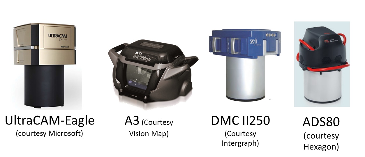 Figure 2.3 Large Format Aerial CamerasSource: (as cited by each image)
 - Medium Format Cameras (not compact): These are cameras that are smaller than large format cameras and more suitable for medium and large UASs. Cameras in this class are still too heavy for small UASs. They are widely used for manned aircraft and can be suitable for large size UASs.
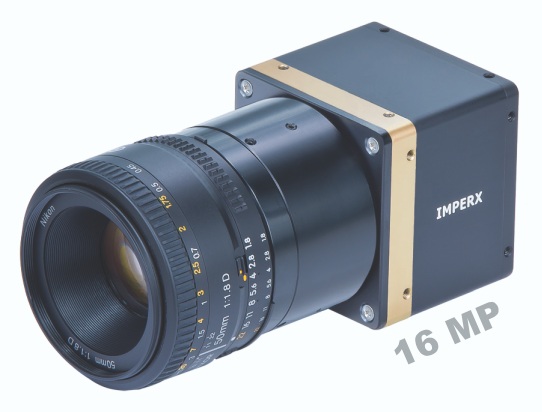
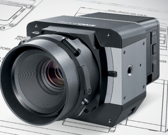
- Small and Medium Miniaturized Format Cameras: This class of cameras is similar to the cameras we own at home and use for recreational purposes, but with compacted size to be suitable for UAS use. Miniaturized cameras are the newest development in the field of digital cameras; they are developed mainly for small UASs. Examples of miniaturized cameras are the Imperx Bobcat 2 [6]camera (Figure 2.4), which has a 16 mega pixel array, weighs only 369 grams (13 ounces) and has a length of 53 mm (2 inches), and the iXA [7] camera system from Phase One Industrial (Figure 2.5). In their latest development, Phase One released their latest payload for UAS, the P3 DJI [8] which is based on mounting an iXA on DJI M300 using DJI mounting hardware and app. Here is additional information [9] about the Phase One suite of sensors for UAS.
- Large Format Cameras: These are mainly used on board manned aircraft and large UASs. They are very heavy for small and medium-sized UASs. Large format cameras are used to cover large areas, such as entire counties or states. Figure 2.3 illustrates a few of the most common aerial cameras used today.
- Infrared Sensors: An infrared sensor operates in the infrared range of the electromagnetic spectrum. Infrared sensors for remote sensing are designed to operate in two regions of the electromagnetic spectrum (EMS), those are:
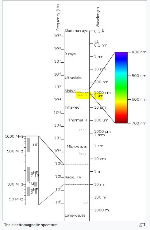
- The Near Infrared Region (NIR): NIR is barely outside the Red of the visible region of the EMS, see Figure 2.6. When the NIR band mixed with the red and green bands of the visible light, it forms a false colored infrared (CIR) image when it is displayed in the order of NIR, R, G instead of the usual R,G,B. False colored infrared imagery is effective in studying vegetation indices and vegetation health and conditions. Precision Hawks runs successful applications [12] for the precision Ag industry. Few sensors designed for UAS to provide multi-spectral imagery, including the NIR band. PARROT SEQUOIA+ [13] is one of those affordable sensors, Figure 2.7.

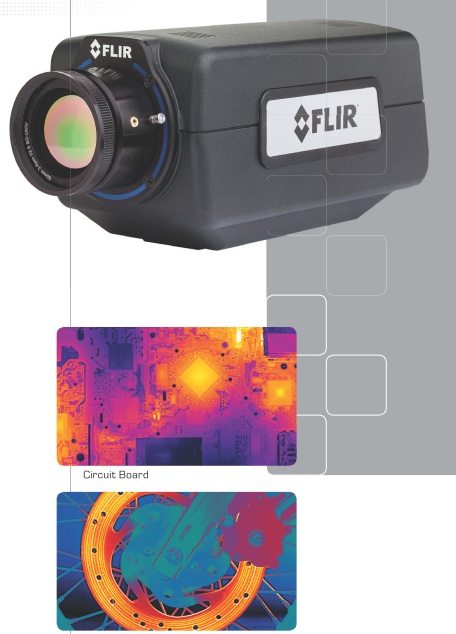
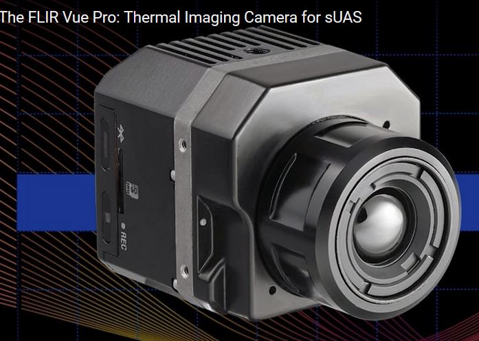
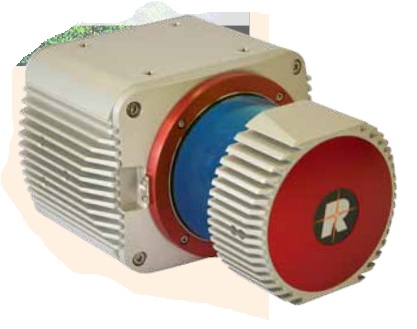
- Thermal Infrared Region (TIR): TIR sensor records the sensed heat and displays it as an image. There are two different technologies used in building such sensors. The uncooled sensor is usually less expensive and less sensitive when compared to heavyweight cooled sensors. Thermal Infrared sensors are widely used for survey and inventory of buried hot water and steam pipes and to inspect heat loss from these pipes. They are also employed for roof inspection, looking for water leaks and heat loss. An example of an infrared sensor is the FLIR A6700SC, [16] shown in Figure 2.8. Recently, FLIR offered a suite of smaller thermal infrared cameras suitable for small UAS such as the VUE PRO, Figure 2.9. In a teaming agreement with DJI, new payloads by DJI such as Zenmuse XT simultaneously carry an RGB camera and a FLIR thermal sensor.
- Laser Sensors: These sensors use laser light for range finding. In addition to the laser source, LiDAR systems use GPS and Inertial Measurement Units (IMU) for precise geolocation of point cloud or terrain mapping. Laser ranging, when combined with necessary auxiliary sensors such as GPS and IMU (see details below), makes a laser-based terrain mapping system called Light Detection and Ranging (LiDAR) [18]. LiDAR systems can map the terrain generating point cloud, which can be used to precisely model the terrain below the path of the UAS. Recently, miniaturized laser-based systems started their way into UAS payloads. An example of the compact size LiDAR that is suitable for UAS is the Riegl VUX-1 [19] (Figure 2.10) and Velodyne (Figure 2.11). T o learn more about a few different UAS-based lidar systems and how people are evaluating the quality of its products, I encourage you to watch this video [20] about UAS-based lidar systems evaluation.

- SAR Sensors: Synthetic Aperture Radars are usually employed by the military for reconnaissance purposes. They require large size UASs, as they are heavy. We should not expect a civilian UAS with a SAR system as part of the payload in the foreseeable future.
Auxiliary Sensors for the Unmanned Aerial System
Auxiliary sensors here mean the navigation sensors that are necessary to determine the location and the orientation of the UAS and its remote sensors that are mentioned earlier in this section. For the UAS and onboard sensor position determination, the Global Positioning System (GPS) is used, and for the attitudes or orientation of the UAS and the onboard sensors, the Inertial Measurement Unit (IMU) is used.
Global Positioning System (GPS)
The GPS does not need introduction, as everyone is familiar with its definition. It is the same GPS that you might use to drive around town. However, GPS that is used to determine a remote sensor position usually undergoes a post-processing to enhance the accuracy of the position.
UAS are offered with two grades of GPS accuracies. The most common one is the single frequency GPS receivers as it is cheaper, and it does not require post-processing or real-time correction service. Such receivers provide location accuracy of around 1 to 2-meter. For more accurate geospatial products generation, the more accurate dual frequency receiver and precise services are need needed. The latter receivers offer two modes of operations, both of which yield positional accuracy of 1 to 3 cm with little or no ground controls required for the project. UAS vendors are fielding systems with two operational modes, those are:
- The real-time kinematic GNSS (RTK) mode: This mode of operation allows the UAS to receive in real time GPS positions corrections from GPS correction services. This mode of operation has particular requirements:
- RTK requires a GNSS base station equipped with a transmitter with a reliable link to a fairly dynamic moving platform such as UAS.
- The rover (on the UAS) itself requires a dedicated receiver for the corrections.
- The post-processed kinematic (PPK) mode: This mode of operation does not require the real time GPS positions correction, as the acquired GPS data can be post-processed at a later date. RTK operations not only require a stationary base station during the UAS mission, but the location of such base station should be surveyed and located before the UAS flies the project, something may complicate the deployment of the mission in some circumstances. Although PPK requires a base station as well, the base station’s precise location can be determined later after leaving the project area.
In principle, both RTK and PPK promise positional accuracies at the 1-3cm level. The main purpose of RTK and PPK is to minimize or eliminate the need for ground control points, thereby reducing cost. For more details on GPS, please visit GPS Defined. [23]
Inertial Measurement Unit (IMU)
An inertial measurement unit, or IMU [24], is an electronic device that measures and reports on aerial vehicle velocity, orientation, and gravitational forces using accelerometers and gyroscopes. IMUs are typically used to control and maneuver manned aircraft, unmanned aerial vehicles (UAVs), and satellites. Another important use for the IMU is that it helps IMU-enabled GPS devices to maintain positioning information when GPS-signals are unavailable, such as in tunnels, inside buildings, or when electronic interference is present.
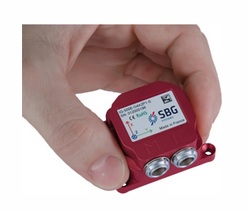
The IMU is the main component of inertial navigation systems (INS) used in aircraft, spacecraft, watercraft, and guided missiles in Geo-spatial mapping activities. The data collected from the IMUs sensors allows us to determine the orientation of the sensor, which is an important aspect in geolocating on the ground each pixel of the sensor. The IMU, like other components necessary for the operation of UASs, is miniaturized in weight and size to make it fit on small UASs. An example of these small IMUs, which are mainly designed for UASs, is the SBG 500E, [25] illustrated in Figure 2.12.
For more details on the IMU, you can visit the IMU Wikipedia page [24].
To Read
- Section 3.5 of Chapter 3 of Introduction to the Unmanned Aircraft Systems
- Chapter 10, 11, and 12 of Introduction to UAV Systems (Aerospace Series)
Launch and Recovery
The launch and recovery element is an area that requires the most human interaction. Some UASs require elaborate launching procedures, while others can be hand thrown toward the sky. Some large UASs require long runways and other field support equipment such as fuel trucks, ground power units, and ground tugs. Similarly, the requirements for recovery procedures vary widely. Most small UASs that are used for geospatial projects require simple procedures and can be hand held or launched with the use of a catapult.
Some UASs, such as target drones, are air-launched from fixed-wing aircraft. Usually, large UASs are equipped with wheels for takeoff and landing and do not need special equipment, while smaller UASs need a variety of launch and recovery strategies depending on the complexity of the system.
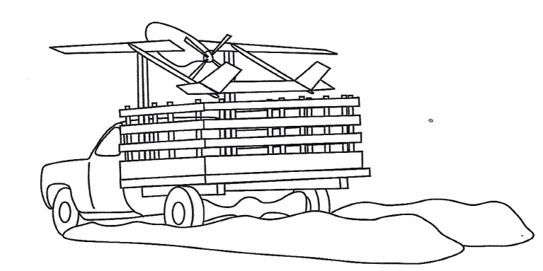
A truck driven at a speed of 60 mph can be used to launch a small UAS assuming that the launching site contains a smooth surface for the truck to use. In this type of launching method, the UAS is held in a cradle above the truck cab with its nose pointed high toward the launching path, Figure 2.13. Once speed is sufficient for takeoff, the UAS is released and lifts upward toward its takeoff path.
Many small and medium-sized UAS launch systems have a requirement to be mobile, or in other words, to be mounted on a truck or a trailer. Such mobile launchers fall within one of the following types:
- Rail Launchers: The UAS is held fast to a guide rail while it is accelerated to launch speed.
- Pneumatic Launchers: Compressed air or gas is used to provide the necessary force for launching the UAS.
- Hydraulic/Pneumatic Launchers: Compressed gaseous nitrogen is used as the power source for launch.
- Zero Length Rocket Assisted (RATO) Launching: There is no rail or track used in this mode of launching. The UAS rises directly from a holding mechanism, and it will be in free flight once the rocket is fired.
For more details on these launchers, refer to chapter 17 of the supplemental textbook Introduction to UAV Systems, 4th edition.
To Read
- Section 3.6 of Chapter 3 of Introduction to the Unmanned Aircraft Systems
- Chapter 17 of Introduction to UAV Systems (Aerospace Series)
The Human Element
Like any other technology that requires human intervention for the safety of operation, human involvement is considered to be the most important element for the successful and safe operation of the UAS. Even with autonomous flights using autopilot, the human role during launch and recovery is crucial to the operation of the UAS. As navigation technology develops further, the human role in operating a UAS will diminish dramatically.
The human element is key in almost all operational aspects of any UAS and plays a great role in the success and survival of its operation. Starting with mission planning, humans have to design and arrange a concept of operation in order to guarantee success. Equally important is the human role in the flight control process. Autopilot can do only so much without the guidance and intervention of the operator.
The role of the pilot and the observer cannot be underestimated, as without them the flight will not occur. This is true even with the most sophisticated drones, such as the Predator. Even the Predator, with sophistication and automation built in, needs a pilot to fly it. The human element is involved in all of the following aspects of operating a UAS:
- Mission planning and control: has to be performed by an operating team.
- Launch and recovery procedure: has to be performed by an operating team.
- Payload management and control: has to be managed by an operating team.
- Data links monitoring: has to be managed by an operating team.
- Ground support equipment coordination and management: has to be performed by an operating team.
Automation in operating a UAS results in less human intervention, but it will never eliminate the role of the human in such an operation. Imagine that an airline invites you to be on board an airplane flown solely by autopilot. There are no pilots on board. Would you accept such an invitation? I am certain your answer would be a big NO. Using the same analogy, could you imagine operating a UAS, which is less sophisticated than a jetliner, without a pilot and without an observer? That is how important the human role is in operating a UAS. That is at least true for the time being. Who knows what the future may bring to this field.
To Read
- Williams, K. Human Factors Implications of Unmanned Aircraft Accidents: Flight-Control Problems [4], FAA report, DOT/FAA/AM-06/8 Office of Aerospace Medicine Washington, DC 20591- April 2006
Summary and final tasks
Summary
Congratulations! You've finished most of the Lesson 2 material. What I hope you learned from this lesson is all you need to know about the different elements that form a UAS. The payload section is very valuable to individuals with background in geospatial mapping, as it goes through the different sensors utilized by the industry today. Understanding the functionality of each of the UAS elements will help you in the common lessons, where we are going to talk about Concepts of Operation (CONOP), risk assessment, and Certificate of Authorization (COA). Therefore, please make sure that you understand the different topics of this lesson and do not hesitate to ask questions.
Final Tasks
| Task | Description |
|---|---|
| 1 | Complete Lessons 1 & 2 Quizzes |
| 2 | Complete the discussion assignment on SWOT analysis in lesson 2 on CANVAS |
| 3 | Install Pix4D software. Pix4D is the data processing software you will use to process UAS imagery. Follow the instructions in Canvas. |