4.2 Introduction to CityEngine and its CGA Shape Grammar
4.2 Introduction to CityEngine and its CGA Shape Grammar
Introduction
In this section, we focus on an introduction to ESRI CityEngine as an instance of procedural (grammar-based) modeling software. Although this software won’t be used in this course, the result of its procedural modeling will be applied in lessons 5 to 7 that will introduce you to ArcGIS Pro. CityEngine is standalone desktop software. ‘The computer is given a code-based ‘procedure’ which represents a series of commands - in this context geometric modeling commands - which then will be executed. Instead of the "classical" intervention of the user, who manually interacts with the model and models 3d geometries, the task is described "abstractly", in a rule file’ (CityEngine [1]). The set of generic procedural rules can be used or modified when creating virtual cities. Moreover, new procedural rules can be defined, modified, or rewritten to create more detailed and specific designs.
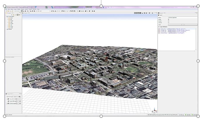
Please watch the video below to learn more about the user interface and navigation in CityEngine.
Video: CityEngine Essential Skills: Exploring the User Interface and Navigation Controls (15:47)
This tutorial will give you a quick overview of CityEngine's navigation tools and user interface. And for this project, we'll use the International City we created in the previous tutorial. If you're just joining the series, you can create this project through the City Wizard. To access the City Wizard, go to the File menu and click New. This will open a new dialog box and you can choose City Wizard in the CityEngine folder and then click Next. Give a name to your city. I'm gonna call this one International City. And for our purposes, we can just accept the defaults and scroll through the wizard. Once you're done, click finish. And for me, I've already created this city, so I'll click cancel. Now your city might take a little while to generate but pretty soon you'll have something that looks similar to what you can see here.
Now for this lesson, let's set up a scenario. So just imagine that you're an urban designer and you've been charged with creating a new residential development. To help you complete this task we'll build your understanding of the user interface and develop your skills using the navigation tools in CityEngine.
First, let's look at the main windows in CityEngine. The first is the scene editor. In our scene, we have the environment layers that control the scene's light and the scene's panorama. One of the functions of the scene light layer is that I can come in here and change the solar intensity values. I can decrease intensity to maybe 0.5 and we can see the light change in the scene. I'm going to set it back to 1 just to make the scene a little brighter.
Next, we have map layers and these contain images that make up the base map and the context for your scene. We also have something called the obstacle map layer and this constrains where the city will be generated. So if I go ahead and turn off the heightmap layer, and turn on the obstacle layer, you can see those areas in black represent areas of vegetation and water in the landscape. And CityEngine recognizes that it can't go ahead and build buildings in these areas. So this is a useful way for you to help constrain where your city will actually be generated.
Finally, we have graph layers. What we can see here is a street layer and it's made up of networks. And these are like our edges and nodes and blocks, and these are used for generating shapes and models dynamically using CGA rules.
Next, let's look at the Navigator window. The Navigator is used for project and scene management and consists of the folders you can see here. The first is the assets folder. The assets can be in different formats. For example, obj, and these are used by CGA rules to texture the models you see in the scene. Next is a data folder. I use this folder to store GIS data in a file geodatabase format. You can store things like colada files or other additional datasets here too. The images folder stores additional imagery like viewport snapshots, for example. The maps folder contains the images used by the map layers. So for example, we have the texture image that's creating the base map for this scene. And we also store the obstacle image here that we saw earlier. The models folder is where you can store 3D models exported from the CityEngine scene. The rules folder contains the CGA shape grammar rule files. And these rule files call on the assets that we saw earlier to create the textures for the 3D models. And next is the scenes folder. So the scenes folder is where we store all the scenes that we build in CityEngine. And finally, we have the scripts folder where you can store things like Python scripts.
If you ever need to add any additional data to any of these folders you can easily do that by dragging and dropping from your native file browser. You have the option here to configure the drag-and-drop setting, so I can link to files so if they're updated on my folder system they'll update directly in my navigator or my workspace as well. Or I can choose to copy the datasets into the workspace. Besides project management, this window lets us open a scene by right-clicking and we can also access the CGA rule editor window by double-clicking on one of the CGA rules in the rules folder. Once the CGA rule editor is open, we have the option to view and edit the rules either in a text view, which we can see here, or a visual view. And we'll cover CGA rule editing in more detail later. And I'll just switch it back to the textual view.
Now let's take a look at the inspector window. The inspector shows all the attributes and the parameters of the assigned CGA rules. To view rule parameters, first select some buildings by holding the left mouse button down and dragging from left to right. You see a blue rectangle on the screen and when you release it, you can see some buildings highlighted in blue. And then in the inspector window on the right, you can see under the street parameters, the different values available to change. So we have things like street width and sidewalk width and I can update these based on my design intent or maybe feedback from a client. And finally, we have the log window. And this window is useful for troubleshooting errors or if you're getting any strange behaviors. And it gives you good feedback ranging from informational messages to severe errors like out of memory for example.
Okay, now we have an overview of some of the windows in the user interface. Let's take a look at one of the main windows, which is a 3D viewport. And this is where we visualize and interact with the 3d scene and it's where I'll sketch out the new development. First, let's choose an area suited for new development. From looking at the scene, I think somewhere down by the waterfront would be good. To zoom to this area, hold the left mouse button down and drag from left to right to select some of the streets. Then click on the frame selection tool from the toolbar in the top right of the viewport. This quickly zooms me into the area. Another way to quickly navigate to this area is to create a bookmark. The bookmark menu is located in the top right of the viewport window and it has a small star icon. Click on this and then from the drop-down menu choose to create a new bookmark. I'll call this one project area and click OK.
So now that I've saved the extent of my project area, I can quickly zoom out. So if I press the A key, it will zoom me out to the extent of my whole project. And to zoom back again, I'll go up to the bookmark menu and choose project area. Depending on what you're doing in your project, you might like to have another viewport window open to give you a more complete view of your project or of your scene. So for my purpose. I think I would like to have the perspective scene as well as a plan view or a top-down view. To do this, I can open a new viewport window from under the window menu, and I can click and drag the viewport and drop it below my original viewport window. If I click on the camera views, you can see that this is in a top-down view. Now I chose this view for my specific purpose, but there are also a number of default views that you can use and they're designed for other tasks. So the first one is called the default view, handily enough, and this one is really good for an overview of your scene and for management tasks like import and export. The next one we'll take a look at is called the minimal layout. Now this one has a perspective view and some editors open, which makes it pretty good for presentations. The next two views are similar to the default views, but we get two views. So we have a perspective at the top here and a plan view at the bottom. And you can also have this in a vertical layout. And then finally to make rule editing more efficient, we have a couple of views here. Let's take a look at the standard rule editing view. This layout has one perspective view and leaves more area for the CGA editor, so it's especially suited for editing rules.
Okay, now I'm just going to return to the default layout because that's going to suit my purpose of sketching out the new development. Now before we get started with some of the navigation in the scene, I want to show you some of the view settings that you can adjust, so you can see the models better. So under the view settings menu, here I'm going to uncheck Wireframe on Shaded Textures. And now we can get a better view of what our models are going to look like. Now let's save this perspective view. So under the window menu, choose Layout and then Save Perspective As. Then all you have to do is give this a name. For me, I'll call this project view and choose okay. So now I have this perspective saved if I ever want to use it in a future project. Now I have a viewport layer, let's look at how to navigate. So I can use the navigation tools, tumble, track, or dolly. Or it's even easier to use the shortcut keys. So here we have alt and the left mouse button and to pan, alt and the middle mouse button and then to zoom in and out, I'm using the alt key and the right mouse button. A recommended navigation workflow is to select the features or the area that you want to work in and choose a frame selection tool. Once you're zoomed in closer, you can explore the selection using the tumble, track, and dolly shortcut keys. Also, if you ever want to deselect a selected feature, you can just hold down the ctrl, shift and A keys.
Now let's look at how we can interact with the models in the viewport using selections. Selecting features is also an essential skill for applying rules. So one way we can select features is using a rectangle. So here from left to right if I drag, I select all the features that fall inside the rectangle. But if I go from right to left, I get all the features that touch the borders of the rectangle, as well as fall inside. Another thing I can use is from the selection menu. So I can choose to subtract from the selected features, and we see the result there. I can also do things like invert the selected features, and we can see the results in the window here. And then to deselect the selection, you can do control, shift and A.
Now let's see how we can use selections to apply rules for their new development. In this step, we'll use some of the object edit & transform tools to create the new development. First I'll zoom back to the study area using the bookmark. And the tools that we're looking for are located here above the viewport. I'll select the polygon street creation tool and quickly sketch out some streets and blocks for the new development. I'm going to select some of these blocks, so I'll do the drag a rectangle selection technique. And if I right-click, I can choose select, and from the context menu, I'm going to choose select objects of the same group. Then under our block parameters in the inspector window, I'm going to change the type to recursive subdivision, and adjust some of the lot areas. Once I'm happy with the design, I'll go back in and select the blocks again, and right-click and choose select objects of the same group. And then I'm going to drag and drop this international city rule directly on to my selected features. And straightaway you can see we've generated a new urban development. So in the inspector window, you can see under the International City group we have some parameters available to change. So under type, we have different building types, high-rise, office, residential. I'm going to leave this as apartment.
And sometimes when you're working with a complex scene like this one, if you want to make an edit, it's useful to be able to select the building you want to interact with and then isolate it. So to do that, select a building with your selection tool and then press I on the keyboard to isolate the selection. And then you're able to come in and edit the specific building you're interested in. So here I'm changing the tree type to a random forest mix, and I'm changing the building type to an office building. So once you're happy with your edits, you can press I, and your models will come back. Now if we press the A key, we can zoom out to see the entire scene. I'll zoom in a little bit here. When you're finished with the visualization and you want to see perhaps more of your model, you can press the spacebar and this will maximize your screen real estate by hiding some of the other windows. Now we'll change some of the display settings so we can see the models a little bit better. So here I'm going to add some shadows. I think I'll also add the ambient occlusion as well. And then we'll turn off the grid that you can see there so we can better see the models. These kinds of view settings are really good if you want to take some high-quality screenshots of your CityEngine scene.
Okay, so now you know your way around CityEngine. You'll use your navigation skills and project management knowledge in the next tutorial, which shows you how to create your first CityEngine project.
Transforming 2D Data to 3D Assets
Transforming 2D Data to 3D Assets
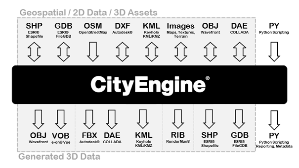
CityEngine is suitable for transforming 2D GIS data to 3D cities. GIS data such as points, lines and polygons can be used to create 3D models. The current version of CityEngine connects to ArcGIS through data exchange. However, it is not tightly integrated into the ArcGIS system yet. The created 3D models can be exported to other software for analysis or editing such as ArcGIS, Maya, 3ds Max, Google Earth, the Web (see Lesson 7) or Unity (as we’ll explore in Lessons 8 and 9) (CityEngine Frequently Asked Questions [3]). The following figure shows different data formats of input and output to and from CityEngine. CityEngine does not support automatic creation of 3D city models. The platforms that support automatic creation of 3D models in urban environments, use oblique imagery or LiDAR data to reconstruct volumes and building shapes based on point clouds and aerial imagery. However, the main strength of CityEngine is data creation, the use of other datasets such as geodatabases and export capabilities. A single procedural rule can be used to generate many 3D models. GIS data feature attributes can be used to add more accuracy to the model. Instances of such attributes are building height, number of floors, roof type, and roof materials.
Understanding CGA Shape Grammar
Understanding CGA Shape Grammar
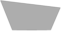
As mentioned, CityEngine uses a programming language called CGA shape grammar. Rules written with CGA are grouped into rule files that can be assigned to initial shapes in CityEngine. For instance, 2D building footprint polygons can be assigned a rule file containing the rules for interactively creating building models from the 2D polygons as illustrated in the figure below. One of the rules defined in the rule file needs to be declared as the starting rule, meaning that the generation of the building model will start with that rule.

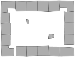
The initial shapes to start the iterative refinement process can be created either in CE or imported from another source. More precisely, there are three ways of creating shapes in CityEngine (see image below): (1) manually creating shapes, (2) deriving shapes from a graph (e.g., street segments and lots from road network), (3) importing shapes (e.g., 2D building footprints from a shapefile).
All CGA rules have the format Predecessor --> Successor
Where “Predecessor” always is the symbolic name of the shape that should be replaced by the “Successor” part on the right side of the arrow. The “Successor” part consists of a number of shape operations that determine how the new shape is derived from the input shape and symbolic names for the output shape(s) of the rule (which can then be further refined by providing rules where these shape symbols appear on the left side of the arrow). To give an example, the following two rules create a block separated into 4 floors from a 2D polygon:
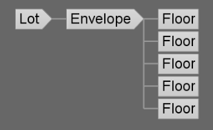
Lot  --> extrude(10) Envelope

Envelope --> split(y) { ~2.5: Floor }*
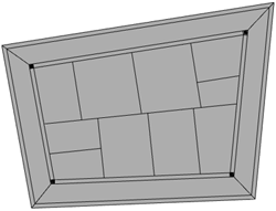
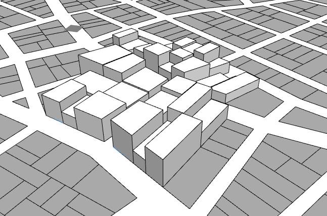
The first rule states that the initial 2D shape (“Lot”) should be replaced by 3D shapes called “Envelope” that are produced by extruding the initial 2D polygon by 10 units. The second rule says that each “Envelope” shape created by the first rule should be split along the vertical y-axis into “Floor” shapes of height 2.5, so four floors altogether. We could extend this simple example by adding rules for splitting each floor into the front, back, and side facades, applying different textures to these, inserting windows and doors, and so on. Application of a rule file to the initial shapes results in a shape tree of shapes created in the process. The leaves of the tree are the shapes that will actually make up the final model, while all inner nodes are intermediate shapes that have been replaced by applying one of the rules. The shape tree for the simple example would start with the “Lot” that is replaced by an “Envelope” shape, which in turn is replaced by the four “Floor” shapes making up the leaves (see figure below).
CGA defines a large number of shape operations (see CGA Shape Grammar Reference [5]). Shape operations can have parameters such as the extrude and split operations in the previous example. Rules can also be parameterized to provide additional flexibility (see Parameterized Rule [6]). Moreover, rules can be conditional (see Conditional Rule [7] or Stochastic Rule [8]), and rule files can contain attribute declarations (see [9]Attributes [10]), function definitions (see Functions [11]), and style definitions (see Styles [12]). If you want to learn more about writing CGA rules, tutorials 6 to 9 at Introduction to the CityEngine Tutorials [13] would be a good starting point.
Using CGA Rules
Using CGA Rules
To create building geometries through CGA rules, the following general workflow can be used:
- In CityEngine, the “Lots” serving as initial shapes for constructing buildings. Lots are either created in CityEngine (drawn or created based on a graph) or imported.
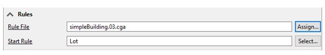
- To create 3D models, the user selects which Rule File (.cga) and Start Rule to apply to these initial shapes. The user can either assign one rule to all building lots or assign rule sets on a selection of buildings.
 Credit: CityEngine Help [4]
 - Then, the user can trigger the application of the rules to the selected shapes. Therefore, it is important that the Start Rule of the shape is present in the rule file. Otherwise, no rule can be invoked. Extrusion is the first step in generating a 3D mass from a 2D footprint. The operations provided in CGA such as “extrude” can be adapted to create a complex architectural design. A simple CGA rule for building extrusion can be written as follows:
Lot --> extrude (4) Building

Or:

attr height = 30

Lot -->extrude(height) Building
 Credit: CityEngine Help [4]
 -
In order to modify the resulting 3D models, different possibilities exist: (1) edit the rules by scripting, (2) overwrite the rule parameters of a rule set on a per-building basis, and (3) if stochastic rules are used (rules with random parameters), the random seed of all or single buildings can be altered. The last method is used in creating virtual cities that should have certain characteristics. These types of randomization are not a representation of reality.
The following figure shows how a rule can be overwritten (2nd method mentioned above). This window provides values to the parameters of a rule. To overwrite the rule, there are some options: (a) to use the rule-defined value, (b) manually add a user-defined value, (c) object attribute, (d) shape attribute, or (e) layer attribute. Layer attribute is to choose attributes based on shapefiles or geodatabases attribute table. For instance, if you have height value as a field in the building footprints’ attribute table, you can use it to automatically generate extrusions. Other instances of fields that can be used for buildings are roof types, roof materials, façade materials, etc.
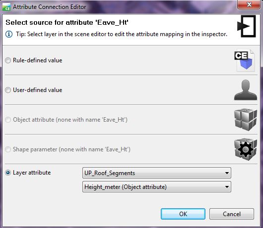 Credit: ChoroPhronesis Lab [2]
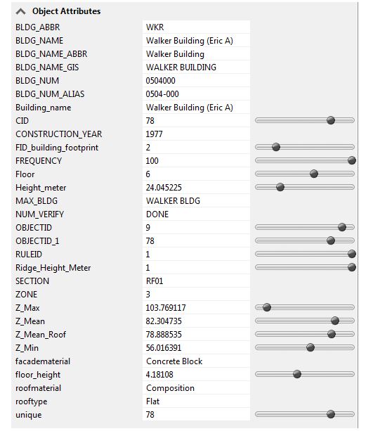 Credit: ChoroPhronesis Lab [2]
 - After the design is finalized, the user can export any selected shapes including buildings or streets to other platforms or publish the results online. (CityEngine [4])