4.3 Introduction to Procedural Modeling for UP Campus
4.3 Introduction to Procedural Modeling for UP Campus
Introduction
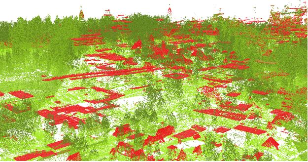
Airborne LiDAR data provides information on variable elevations. This elevation information is useful in both creating the DEM (digital elevation model) and estimating buildings’ height. The airborne LiDAR data collected for Penn State campus is in 25 cm intervals. You can see the Campus LiDAR point clouds of buildings and vegetation in the Figure below. All noises and irrelevant categories are removed for presentation purpose.
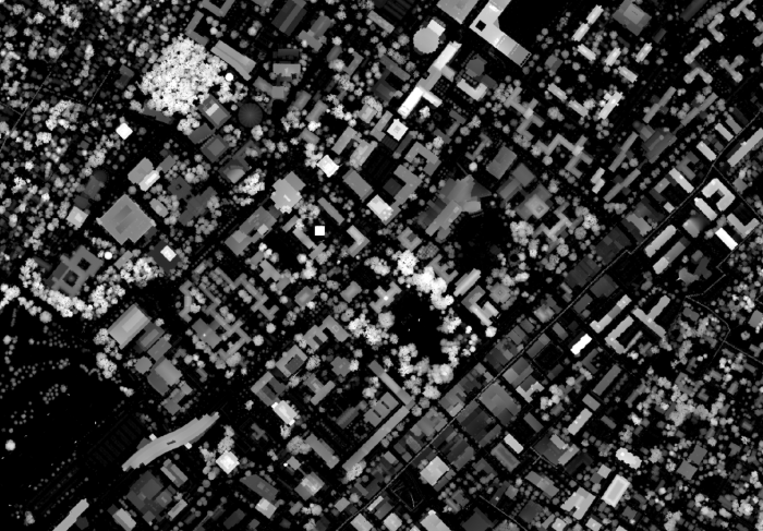
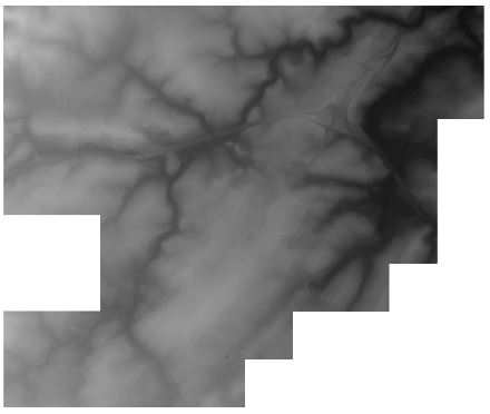
LiDAR returns information for two types of elevation models: (1) DSM or digital surface model (Figure below) which is a first return surface including anything above the ground such as buildings and canopy. (2) Topography: the ground or bare earth which is referred to as DEM (digital elevation model).
Building Footprints
Building Footprints
In CityEngine, for creating a 3D model of Penn State campus, the first step is to insert a DEM. Having a DEM defines the coordinate system and the ground elevation base for locating building footprints and streets. To estimate campus building heights, a digital surface model is created. Based on the normalized DSM layer, the minimum and maximum heights of every point are extracted. Extracting the roof shape and finding the mean of elevation of points within each roof section, the mean of elevation for every part of buildings is calculated (Figure below). All this preparation is done in ArcGIS Desktop to prepare the base shapefile to be imported to CityEngine.
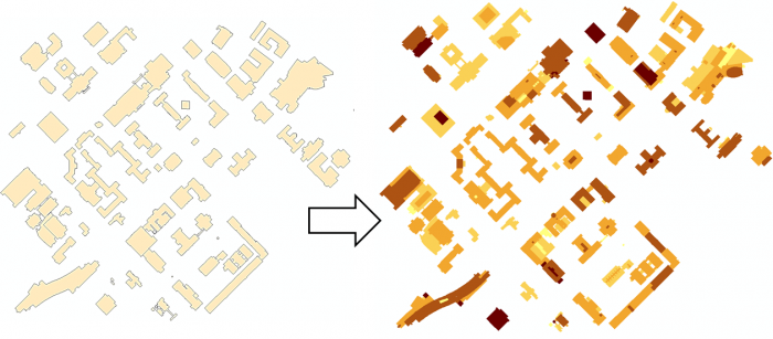
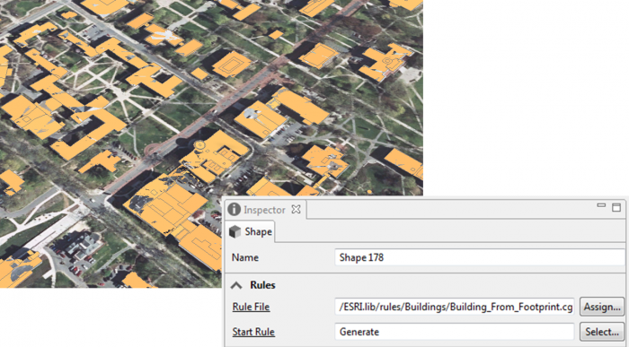
Every single object of the building footprints imported to CityEngine will be considered as one shape or Lot. By clicking on any part of the building footprints, a shape will be selected and you can see the shape number in the inspector menu in the following figure. Each shape has many attributes for each section of buildings such as the mean of height and roof types.
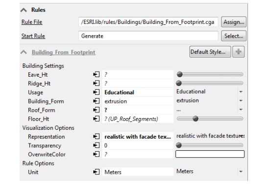
The figure below shows the extrusion rule assigned to the shapes based on the height values in the attribute table.
In the following figure, you can see rule parameters in the building settings that can be overwritten base on layer attributes.
Roof Shapes
Roof Shapes
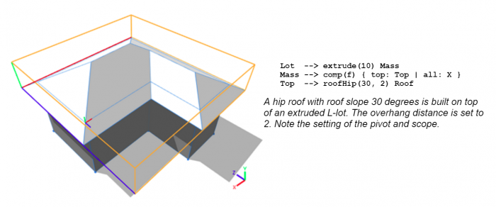
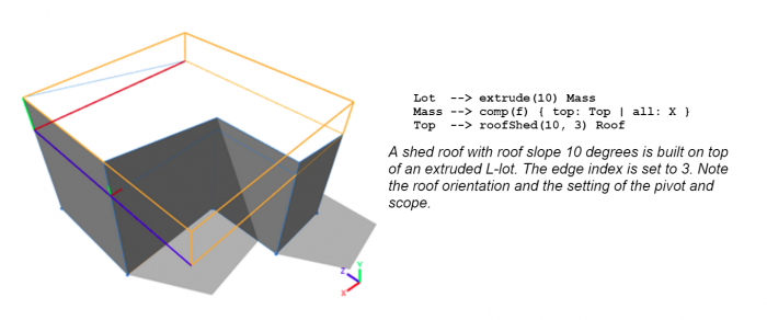
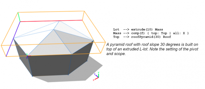
In the CityEngine CGA grammar rules, basic roof shapes such as flat, hip, gable, pyramid, and shed are defined. Examples of basic rules for different roof shapes are as shown in the figure below:
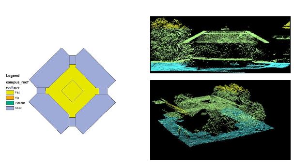
However, roof structures of campus buildings are complex. For more realistic and sophisticated roof types, new specific rules should be written for each complex building and this inverts the aim of procedural modeling which is facilitating the modeling process instead of hand modeling each building. Instead of writing complex rules or assigning one roof type for each building footprint, a combination of roof types is used for each building. In other words, each section of a building with a different height value has a roof type assigned to it. This has been possible by the use of LiDAR information. Each building is divided into different roof sections based on different heights and types. For instance, the following figure has a complex roof type. The middle parts are flat with various heights. The edges are shed and need a different rule to be applied.
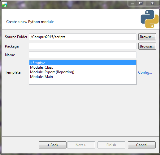
A ‘roof type’ attribute has been created for the building footprints shapefile based on Google Earth images. To select different shapes with similar roof types in CityEngine, a simple python scripting is written. The python editor is executed inside CityEngine and is convenient for writing scripts and executing. The figure below is the window for creating a python module and the next figure shows a sample python code for selecting roof types of the same value.
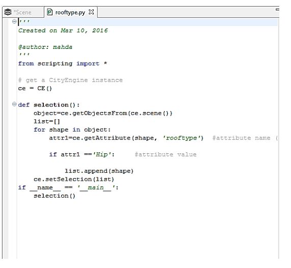
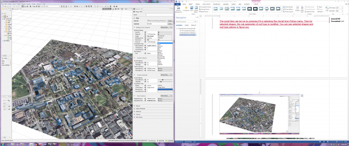
The script then can be run by pressing F9 or selecting Run Script from the Python menu. Then for selected shapes, the rule parameter of roof type is modified. You can see selected shapes and roof type options in the figure below.
Facade, Trees, Plants
Facade, Trees, Plants
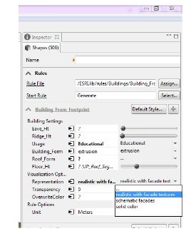
CityEngine rule file of ‘Building_From_Footprint.cga’ has three options for generating façade textures: (1) realistic, (2) Schematic, and (3) solid color. In the Figure below, you can see the three options for façade representation. You are going to explore these options in ArcGIS Pro. ESRI has a library of façade textures for different building types which we have used to texturize campus model. However, for a more realistic view of campus, images from building facades can be captured and used in this model.
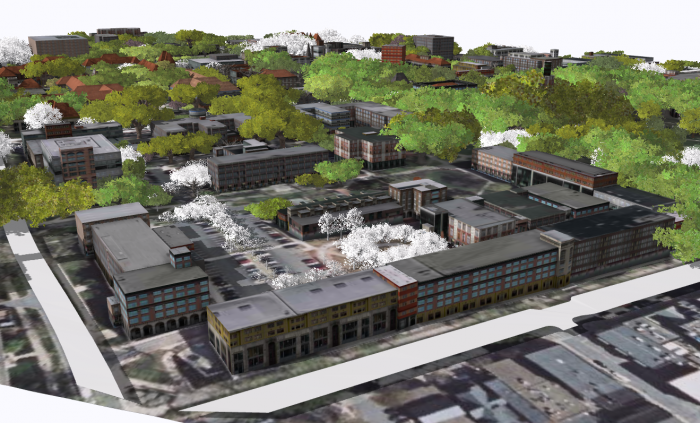
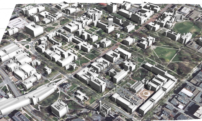
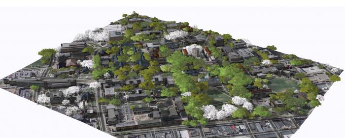
In the images above, you can see that trees have been generated for the campus model. These trees are based on a tree dataset in GIS which has been linked to tree models using “3D Vegetation with LumenRT Models”.This rule [3]covers a lot of common trees found in North America. the models can be previewed in this Link [4].
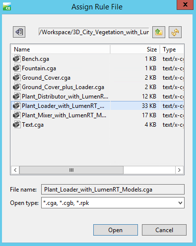
The first step in creating tree models is to Match LumenRT model names with your tree names. This rule file uses the common name of tree species as the identifier of each model. Therefore, it is very important to keep your tree name in accordance with the name in the rule file. You can achieve this by adding a field in ArcGIS and filled it with the corresponding LumenRT names using Python or create an excel file where you match LumenRT tree name with your own dataset, and then link this file with your original dataset in ArcGIS. The second step is to import the tree dataset to CityEngine and align shapes to the terrain.
Selecting the tree shapes, you can assign the rule file and generate the rule.
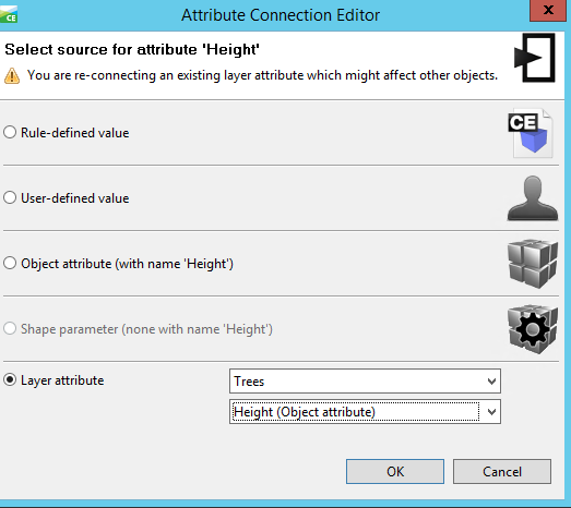
After generating the rule, you may find that the tree models generated are not right. In this step, you need to assign the attributes from the dataset to rule parameters. To do this, simply click on the Attribute Connection Editor near the Name, select layer attribute, and find the field you add to your tree dataset.
To use the created models, you have two options: (1) export it to other formats, and (2) share it. The model can be exported to different formats such as Autodesk FBX, Collada, KML, and OBJ. For sharing the model, one option is to share the whole scene in the CityEngine Web Viewer. Another option is to share the rules as a rule package that can be used locally on your machine. Having the rule package (RPK), you can share it with others using ArcGIS Pro or ArcGIS Online. In Lesson 5, you will learn how to apply a rule package exported from CityEngine as a symbol layer to your database.