Unity Interface and Basic Unity Concepts
Introduction
Unity Interface and Basic Unity Concepts
Introduction
A Unity project consists of one or more Scenes and each Scene is formed by a set of GameObjects located in the Scene. The name GameObject obviously is based in Unity’s main purpose as a game engine but these entities can be anything that we would want in a 3D application: 3D models of buildings, terrain, lighting sources, cameras, avatars, etc. They can also be non-physical things, in particular, abstract entities just serving as containers for scripts that perform some function such as realizing changes in the environment when the 3D application is executed. The main programming language used to write scripts in Unity is C#.
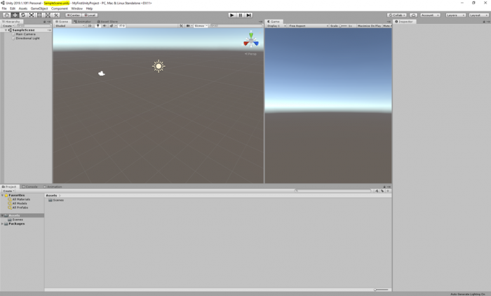
When editing a project in Unity as well as when executing a Unity project, only one Scene is active at any given moment. Each Scene has a name and you can see the name of the currently active Scene in the title bar: There are four parts separated by hyphens, the version of Unity, the name of the Scene, the name of the project, and the platform currently chosen to build the Unity project for. The Scene name part right now will be “SampleScene” as this is a default scene automatically create by Unity whenever a new project is created.
In a computer game built in Unity, each level would be a different Scene. In addition, things like cut scenes and menu screens would also be realized as individual Scenes. The game code will then have to implement the logic for switching between the Scenes. Similarly, in a non-game 3D application, you could also have several Scenes to switch between different environments, e.g. an outdoor model and several indoor models.
To give you an example of having more than one scene in a project, as well as how a scene can be populated with gameobjects, we have prepared for you a unity package that contains a scene called “Main”, populated with terrain, and a few classic buildings of the PSU campus in State College. Download this Unity Package [2]. Once the download is complete, simply double click on it, and an import window inside the Unity editor will pop up showing the folder structure inside the package. By default, all the folders should be selected. Click on import, and all the selected folders will be added to the “Assets” structure of your project. If you receive a warning saying that the package was exported using an earlier version of unity, simply click on "Continue".
This is a relatively large package (almost 200MB), and therefore it could take a while before the import is complete.
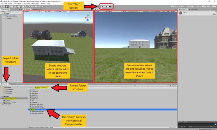
Once the import is finished, you may notice that a new folder called “Historic Campus” is added to your project folder structure under Assets (highlighted in the figure below). In addition, another folder with the title “Standard Assets” is also added, which is a collection of ready-to-use assets provided by Unity to speed up development time. The standard assets folder contains a “first-person controller” prefab that is used in the historical campus scene.
This folder structure is used to organize the resources of your project. It is good practice to organize your files into folders based on some meaningful structure and add a sensible title to the folders.
If you select the “Historic Campus” folder with your mouse, you can see that its contents are listed on the down-center part of the project panel in the editor. This is another way to view and navigate your project folder structure. There are several subfolders inside the Historic Campus folder that contain the 3D models, textures, and other resources used in the scene. To open the imported scene of the historical campus, simply double-click on the “main” scene. We will this scene to go over the basics of unity.
If you click on the small “Play” button on the top center of the editor (alternatively you can use the “Ctrl + P” shortcut), you can run the scene and see it in action. Currently, the scene has three buildings, a simple flat plane, and a first-person controller. Use your mouse to look around, and the WASD keys to navigate the environment. Once you are done experimenting, you can stop the scene from running by either clicking on the play button again or pressing “Ctrl + P”.
Overview on Main Windows in the Project Editor
Overview on Main Windows in the Project Editor
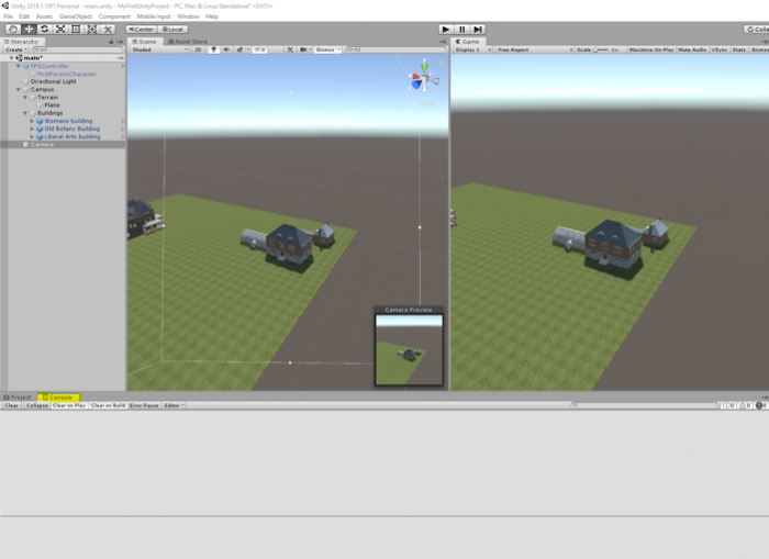
As you may have already noticed in the previous section, there are two main windows in the editor that show two different views of the scene. The window you will mostly look at when creating a Unity project is the Scene Window currently open in the left-center of the screen. It shows a 3D view of the Scene you are currently working on, in this case consisting of a few historic PSU campus buildings from the year 1922 and an underlying plane. The window on the right-center of the screen is called the game window and shows the output of the scene when the project is built. The game window allows you to have a feeling of how this scene of your virtual experience will look like from a user’s perspective, while you are developing. Evident from its title, and as you have already experienced, once you “play” your scene you experience it in this window.
You can alter the arrangement of all the panels and windows to your liking by simply dragging them around. For instance, if you prefer not to see the game window while you are editing your scene, you can drag its panel header and drag it next to the scene window and then drop it.
Video: Unity - Moving windows around (00:12) This video is not narrated.
If you click into the scene window to give it focus, you can then use the mouse to change the perspective from which you are looking at the scene. The details of how this goes are affected by a set of buttons at the top left. The seven buttons on the left are the main ones to control the interaction with the scene and the objects in it with the mouse. For now, make sure that the first button (i.e. Hand tool) is selected as in the screenshot below:

Now go ahead and try:
- Use the mouse wheel to zoom in and out
- Move the mouse with the left button pressed to pan
- Move the mouse with the right button pressed to look around
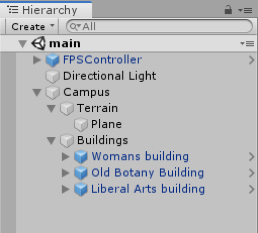
You will learn more details about how to interact with the Scene Window soon. Let us now turn our attention to the panel on the left, which is the Hierarchy panel. It lists the GameObjects in the Scene. Currently, these are the “FPS Controller”, a “Directional Light” and the “Campus” 3D model. The panel is called “Hierarchy” because GameObjects are organized in a hierarchy and the panel shows us the parent-child relationships. The “Campus” object is actually just a container for grouping the 3D objects of the individual buildings, and of the terrain together. By clicking on the small arrow on the left, you can expand that part of the hierarchy and will see the sub-entities of the “Campus” object, called “Terrain”, and “Buildings”. As you probably already noticed, these objects, in turn, are just containers. “Buildings” for instance contains the models of the individual buildings shown in the Scene.
You can double-click on any entity in the hierarchy to change the view in the Scene Window to focus on that particular object. Try this out by double-clicking on some of the buildings, e.g. starting with the “Woman’s building” object.
You may already have noticed that selecting an object in the Hierarchy Window, either by double-clicking it or by just doing a single click if you don’t want the view in the Scene Window to change, has an effect on what is displayed in the window on the right side of the Scene view. This is the Inspector Window, which has the purpose of displaying detailed information about the selected object(s) in our Scene as well as allowing us to modify the displayed properties and add new components to a GameObject that affect its appearance and behavior. If you select the “Liberal Arts” building and check out the Inspector Window you will see that there is a bunch of information grouped into sections, including so-called components attached to the object that will determine how the object will be rendered in the scene. Now compare this to what you see when you select the “FPS Controller” object or the “Directional Light”. Since these are special objects with particular purposes other than being displayed in the Scene, they have special properties related to that particular purpose, for instance, the FPS controller has a child called “FirstPersonCharacter”. This gameobject has a camera component attached to it (as the camera should move when the player character moves around the scene) with multiple parameters (e.g. Filed of view). As an experiment, change the value of the field of view parameter using the slider to see its effect.
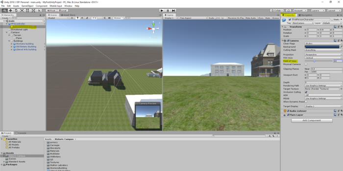
The “Directional Light” is one of several possible light sources that Unity provides. It essentially simulates the sunlight and will be used to render the Scene, resulting in shadows, etc. Instead of having a camera component attached to a child of the FPS controller object, we could have added a static “Main Camera” to the scene. The camera object determines what will be shown when the Unity project is being run, either inside the Unity editor or after we exported it as a stand-alone application. To see the difference, disable the FPS controller and add a main camera to the scene as shown in the video:
Video: Unity - Adding a camera and moving it around (01:06) This video is not narrated.
We first need to disable the FPS Controller by unchecking it in the inspector panel. Then, we need to add a static camera to our scene. To do this, we will click on the GameObject menu on top of the editor and select camera. Next, we need to adjust the rotation and position of our static camera so it captures the part of the scene we want to show. To do this, we will use the menu we have addressed previously to switch our mouse functionalities. In the video, you have seen the use of the Move and Rotate tool. Note that the same results could be achieved by manipulating the numerical transform values of the camera GameObject in the inspector menu. To try this, observe the numerical values while you use the mouse to move or rotate the object, or alternately, change the numerical values to see their effect.
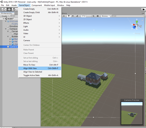
A very handy way to change the camera perspective (and also the position and orientation of other GameObjects) is by first changing the Scene view to the desired perspective and then telling Unity to use that same perspective for the camera object. This can be accomplished by using "GameObject -> Align With View" from the Gameobject menu bar, or by simply using the keyboard shortcut CTRL+SHIFT+F. To practice this, double-click the Old Botany building to have Scene view focus on this building. Now select the Camera object (single click!) and use Align With View. See how the camera perspective in the Camera Preview has changed to be identical with what you have in the Scene view? On a side note, the GameObject menu also has the function “Align View to Selected” which is the inverse direction of “Align With View”: it can, for instance, be used to change the Scene view to your current camera perspective.
The last panel we will cover in this section is the “Console”. This panel displays warning and error message when Unity experiences any problems with your project or prints messages that you log in your source code (e.g. for debugging purposes).
As was previously mentioned, the way the individual windows and panels are arranged here is the default layout of the Unity editor. But you can freely re-arrange the windows in pretty much any way you want, for instance by clicking on the project tab and dragging it to a different part of the screen. The Layout drop-down menu at the top right allows you to switch between predefined layouts as well as define your own layouts. If somehow the layout got messed up, you can select "Default" there and it should go back to the standard layout that we have been using here so far.
By now, you should be able to move and rotate GameObjects in the scene and play and stop the scene. With respect to the latter, there is an important and useful functionality to know about the Play Mode: While in Play Mode (either running or paused), you can still make changes to the objects in your scene, e.g. by changing parameters in the Inspector panel. However, in contrast to changes you make in Edit Mode, these changes will only be temporary; they will not be saved in your Scene. So when you stop play and go back to Edit Mode, these changes will be gone. This can still be very useful because it allows you to try out things while the project is running and immediately see the impacts.
Building a Project
Building a Project
The last thing we want to quickly mention here is how you actually build a stand-alone application from your Unity project, so basically how to create a stand-alone program for a platform of your choice that does the same thing that you get in the Unity editor when in Play Mode. This is done by going "File -> Build Settings…", which opens a new dialog:
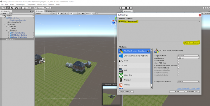
In the pane at the top, you can select the Scenes that should be included in the build. Click on the “Add Open Scenes” button to add the current scene to the build window. At the bottom left, you select the target platform for your build. It is possible to install extensions to build applications for other platforms than you currently see here. The one relevant for this course is “PC, Mac & Linux Standalone” and you then have to select “Windows” as the Target Platform on the right. With the “Player Settings” button at the bottom, you can set more parameters that affect your build. Pressing “Build” will start the process of compiling the stand-alone application, while “Build & Run” will in addition run the program after the compilation process has finished. When you have all parameters for your build already set, you can use “Build & Run” directly from the File menu. When you click "Build" you will be asked to choose a folder to save the project in. In the following save dialog, navigate to your “Documents” folder and use “Walkthrough” as the file name under which the application will be saved. Then click “Save”. Unity will show you the progress bar for building the application which can take a few minutes. If you have a Mac, the windows application would not be played on your computer. You need to create a Mac application.