Operating Procedure
SOP 1: Select Objective
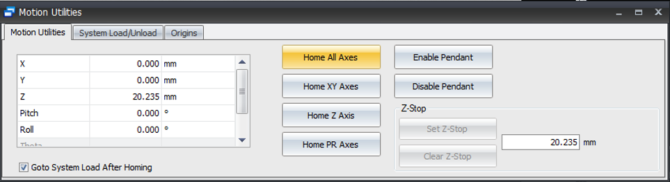
The system should have been left in the Home Position. Verify this before choosing objective.
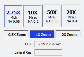
Select your working objective and internal magnification. If you are unsure, make your best guess where to start based on what you hope to learn about the sample.
The objectives selector
There are 4 objectives and 3 internal magnifications giving us 12 different combinations of FOV and Optical Resolution.
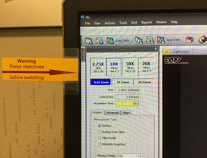
Changing the objective requires the user to raise the instrument up before selecting the new objective (which rotates the turret).
Failing to do so could cause significant damage to the lenses and scanner.
There is a warning reminder on the side of the monitor.
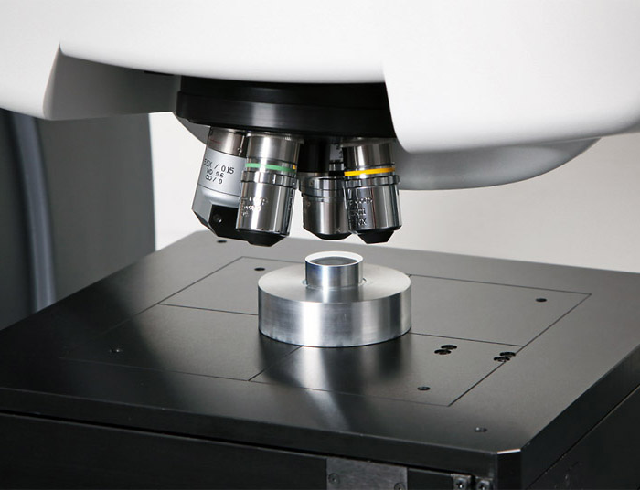
SOP 2: Load the Sample
It is very important when loading the sample to pay attention and not touch any of the objectives on the turret. Doing so can damage the instrument, and it most definitely will mess up the current calibration on the entire turret.
Feel free to navigate the X,Y of the stage to create more room for loading.
Never stick your fingers under the objectives to try and manipulate your sample; move the sample out, make your adjustments and then move it back under with the motors.
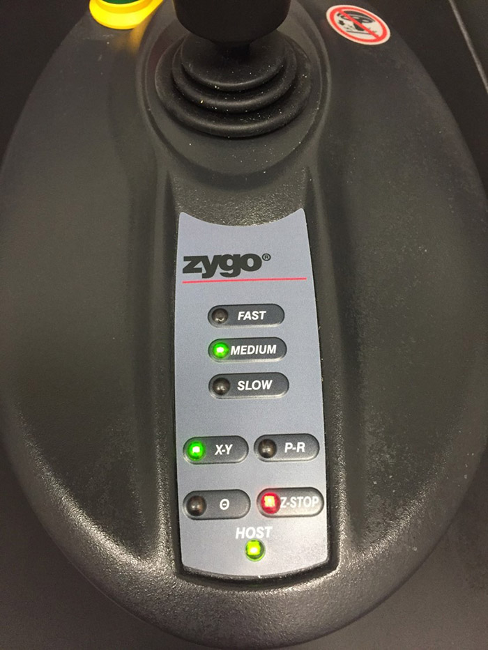
SOP 3: Set the Z-Stop (CRITICAL)
Setting the Z-Stop is broken up into three parts:
Part I. Fast approach.
The goal of this part is to take a good chunk of the Z travel out of the way. Set the Z motor speed to fast, press the Z-Stop button until it is blinking red, and come down until the objective/sample distance is about 1 inch (~25mm).
Part II. Medium approach.
The goal of this part is to SLOW DOWN and get the objective working distance below the surface of the sample being measured. Set the Z-motor speed to medium; leave the Z-stop blinking red.
Part III. Set the Z-Stop.
SOP 4: Move to Focus Position
The instrument is now protected from driving the stage down further than where the Z-stop has been set. The user and the software are prevented from moving below the Z-Stop.

Please watch the following Focus Aid video (:26).
- Move up in Z in MEDIUM speed until the bright spot is centered in the bull's-eye.
- Slow down (with the twist motor control) as you get close to center and attempt to get the fringes visible.
- The brightness of the spot is dependent on the sample. The rougher and more scattering the sample, the more dim this spot will be. It is possible not to have one. In that case, go back to normal view and attempt to focus on the sample surface by eye.
SOP 5: Adjust the Light Level
Please watch the following (:15) video: "Set the Light Level."
- Close the Focus Aid.
- Center the fringes in the view window, making sure the brightest fringe is in the center.

SOP 6: Null the Pitch and Roll
If there are clear fringes (as in this example) or if there is clear X/Y directional trends as the scanner is moved in Z, it is possible to null the pitch and roll.


SOP 7: Set Measurement Setup Parameters
Go to the Measurement Setup Section
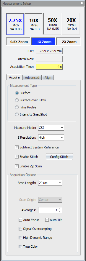
The objective is already chosen. If this needs to be changed, move up in Z, rotate to desired FoV, go back to SOP 1, and start over from the beginning.
Work through Measurement Type, Measure Mode, Z Resolution, Subtract System Reference, Scan Length, Scan Origin, Averages, Signal Oversampling, High Dynamic Range options to set up the scan.
If unsure on an option, pick one and look at the results.
SOP 8: Measure
Please watch the Measurement Setup and Scan video (:56).
After going through the Measurement Setup Parameters:

SOP 9: Adjust Scan Parameters as Needed
At the completion of the scan, check the result in the top right result window of the Measurement Tab.
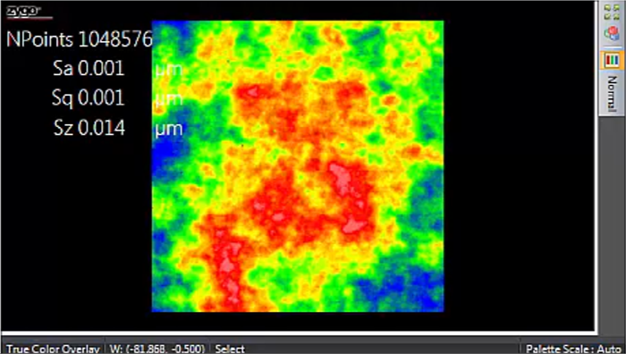
A good scan will have the most NPoints possible for that surface. The total possible NPoints would be every pixel of the camera getting a result which is 1024x1024, or 1,048,576. Not every surface is capable of getting full pixels for the image; the rougher the surface, the more dropped pixels. The only good reason for dropping pixels are near vertical surfaces (since this is a reflection based technique, it cannot collect data from a vertical feature).
If there is large areas of missing data, scan again to try and determine where the Measurement Setup Parameters could be improved.
SOP 10: Home the Instrument when Finished
Since this is a multiuser based instrument, we want to be respectful of all the users that come into the lab. Part of this would be leaving the area neat and tidy for the next user; each user is responsible for their mess. Part of this would be leaving the stage in a safe position while not in use. Every user is asked to leave the instrument the same way.
When finished, while your data is copying to your X-Drive or box.psu.edu drive, please Home the stage.