Pitch, roll, and null
The lateral/Y axis, or pitch axis is an imaginary line running horizontally across the sample through the center of gravity. A pitch motion is an up-or-down movement of the front or back of your sample as mounted on the stage.
The longitudinal/X axis, or roll axis is an imaginary line running horizontally though the length of the sample through its center of gravity. A roll motion is a side-to-side movement or tilting left or right of your sample as mounted on the stage.
To "null" the fringes is to adjust the pitch and roll of your sample so it is parallel to the plan of the interference fringes, which is perpendicular to the Z-scan axis.
Nulling the fringes predominantly helps you with minimizing the scan length needed to measure your surface.
An example for Smooth Flat Surfaces
To "null" the fringes is to adjust the pitch and roll of your sample so it is parallel to the plan of the interference fringes, which is perpendicular to the Z-scan axis.
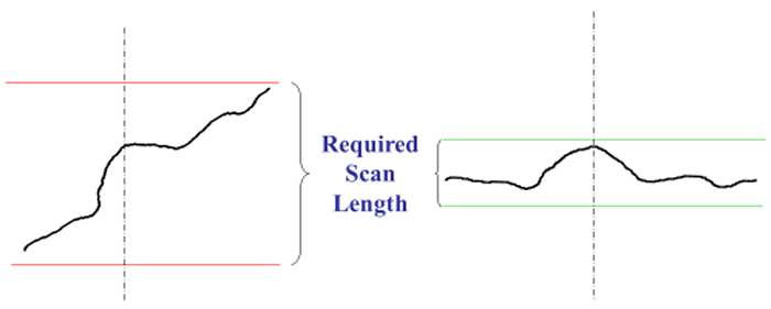
The cartoons to the right show the impact on scan length when a flat part is nulled properly (cartoon on the right with the small green scan length outlined is nulled properly). If the differences in scan length on in a few μm to tens of μm it likely doesn't matter much. If the differences are in the 100s of μm, it will greatly affect your collection time and care should be taken to null the surface as best you can.
For a Smooth Flat Part, adjust for high contrast and the least number of fringes. On very flat parts, it is possible to null the surface such that the fringes take up the entire field of view
Below is a video showing the actual field of view (right) and a cartoon (left) depicting what is happening on a tilted smooth flat part as the instrument is moved up in Z with the joystick. Notice how the fringes travel across the field of view from upper right to lower left. The fringes indicate that not only is the sample tilted, the direction of travel describes how it's tilted. The fringe travel indicates, in this example, that the front left corner of the stage is higher.
Nulling the stage for a smooth flat part gets the sample surface and the Z-travel perpendicular, which means the surface is parallel to the fringes now. As the instrument is moved up in Z now, the fringes can be seen individually as they flash by.
An example for Textured Surfaces
To "null" the fringes is to adjust the pitch and roll of your sample so it is parallel to the plan of the interference fringes, which is perpendicular to the Z-scan axis.
Textured surfaces are very similar to flat surfaces, though it can be harder to see the trend in the tilt of the sample. The goal is to null the overall sample tilt to minimize the scan length.
On Textured or Rough Flat Part the fringes are in smaller isolated areas. Center the fringes and adjust the focus between the high and low fringes. The distinct lines that were seen for smooth surface are broken up with the varying topography of a rough or textured surface. Nulling the fringes involves adjusting the fringes so they enter and leave the field of view without any discernible trend in X or Y tilt.
Below is a video showing the actual field of view (right) and a cartoon (left) depicting what is happening on a tilted textured or rough part as the instrument is moved up in Z with the joystick. Notice how the fringes travel across the field of view from lower right to upper left. The fringes indicate that not only is the sample tilted, the direction of travel describes how it's tilted. The fringe travel indicates, in this example, that the back left corner of the stage is higher.
Nulling the stage for a textured or rough part also gets the sample surface and the Z-travel perpendicular, which means the surface is parallel to the fringes now. As the instrument is moved up in Z now,fringes enter and leave the field of view without any discernible trend in X or Y tilt.
An example for Curved Surfaces
To "null" the fringes is to adjust the pitch and roll of your sample so it is parallel to the plan of the interference fringes, which is perpendicular to the Z-scan axis.
On a Spherical Part, adjust the stage and the focus to center the circular fringe pattern. This can be done by moving in X/Y or in P/R, depending on what you are trying to measure. Depending on the curvature of the sample, nulling a spherical sample can significantly reduce collection time.
Below is a video showing the actual field of view (right) and a cartoon (let) depicting what is happening on a curved part as the instrument is moved up in Z with the joystick. Notice how the fringes travel across the field of view from right to left. The fringes indicate that not only is the sample offset, the direction of travel describes how it's offset. The fringe travel indicates, in this example, that the back sample curvature continues to rise to the left. Either X/Y or P/R can be adjusted to center the circular pattern depending on the users specific needs.
Nulling the stage for a curved part minimizes the total sample height within the field of view. As the instrument is moved up in Z now, the fringes go through a circular, bullseye pattern centered in the field of view.