The Mx™ Measure tab
The Measure tab is where all data collection originates.
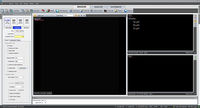
Top Control Bar

The Top Control Bar - Details
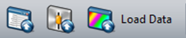
Load application, Load application settings, Load Data - only Load Data is useful to users.
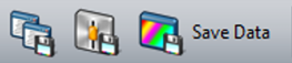
Save application, Save application settings, Save Data - only Save Data is useful to users.

Home - term given to the default screen for a particular instrument and application.
Masks - opens the mask editor.
Auto Sequence - opens the auto sequence editor.
Auto Focus - the instrument scans through a set Z range and attempts to locate the fringes.

Auto Tilt - the instrument scans through a set Z range and attempts to remove the sample tilt.
Auto Focus and Tilt - the instrument performs an auto focus followed by an auto tilt.

Focus Aid (F8) - opens the focus aid.

Auto LL (F9) - adjust the camera shutter and light level. Should be done with the center fringe in the video display.

Measure (F12) - take a measurement.
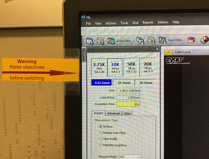
Objective Selection
The objectives selector
There are 4 objectives and 3 internal magnifications giving us 12 different combinations of FOV and Optical Resolution.
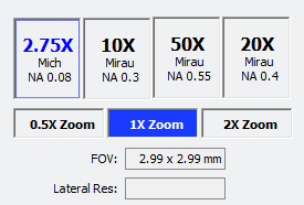
Changing the objective requires the user to raise the instrument up before selecting the new objective (which rotates the turret).
Failing to do so could cause significant damage to the lenses and scanner.
There is a warning reminder on the side of the monitor.
Measurement Type
Selects what characteristics of the test part are to be measured.
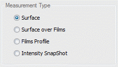
Surface - Use this mode when measuring surface topography on opaque parts.
Surface Over Film - Use this mode when measuring the top surface topography on a part with transparent films. This mode does not provide any information about the underlying film(s). Adds Films tab.
Films Profile - Use this mode when measuring the top surface topography and/or either the bottom surface topography or the film thickness. This mode only returns information about the top-most film when measuring parts with multi-layer film stacks. Adds Films tab.
Intensity SnapShot - Use this mode to measure a 2D intensity snapshot of the scene as represented in the Live Display. The mode may be useful for lateral metrology or feature alignment, but will not provide any information about the surface topography.
Measure Mode and Z Resolution
Measure Mode
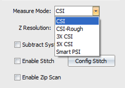
CSI - Coherence Scanning Interferometry -This is the default starting point and good for most parts.
CSI - Rough - This mode makes CSI measurements using a narrower bandwidth illumination spectrum to improve performance on rough parts and sometimes on parts with high slopes. It generally improves data coverage, but with a decrease in vertical resolution. The improvement is part-dependent and should be compared with CSI results.
3X CSI - This mode makes sub-Nyquist CSI measurements at 3X the nominal scan rate to provide higher throughput, but with a decrease in vertical resolution. 3X CSI measurements are compatible with PZT and extended scans.
5X CSI - This mode makes sub-Nyquist CSI measurements at 5X the nominal scan rate to provide even higher throughput, but with a further decrease in vertical resolution.
Smart PSI - Smart PSI combines a CSI scan to focus the instrument and determine the coherence profile of the surface with a series of rapid PSI (phase-shifting interferometry) measurements to determine the high-resolution phase profile of the surface. This mode is ideal for smooth parts with low departure (PV < few microns) and is the best option for super-smooth parts.
Z Resolution
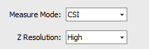
High - The phase and coherence profiles are combined to provide the final height map. Provides highest vertical resolution.
Normal - The coherence profile is taken to be the surface height. Provides most data on challenging parts, but at lower vertical resolution.
Subtract System Reference, Enable Stitch, and Enable Zip Scan options
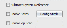
Subtract System Reference - Select check box to use a system reference file. This is used to improve instrument performance by minimizing noise. There must be a valid 3D reference calibration for this to function.
Enable Stitch - Select check box to measure using a configured stitch routine. Stitching is used to analyze areas larger than a single measurement; multiple measurements are combined together.
Enable Zip Scan - Select check box to activate a Zip Scan sequence. A Zip Scan is two or more groups of measurements separated by a vertical distance. A Zip Scan is useful for parts with isolated heights; it effectively extends the scanner range.
Acquisition Options
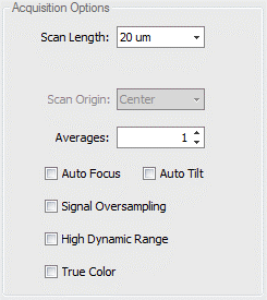
Acquisition Options controls things such as the scan length, scan origin (depending on which motor you are scanning on), averaging, signal over sampling HDR, and true color. The most common reason for dropped pixels in an image is incorrect scan length and/or scan origin. The following sections cover more detail.
7.1: Scan Length and Scan Origin
Scan Length - Selects the vertical scan length. The longer the scan, the greater the height measuring capability, and the longer the measurement time. It is recommended to set to the smallest value that encompasses the part details. When set to Extended, the user enters the length of the scan, which is longer than the selectable lengths. The value entered should be the vertical range of detail in the part plus 10%.
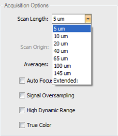
Scan Lengths have two options: It is very important to understand the difference between the two scan length options.
- Numerical scan length choices from 5um-145um (length options change depending on measure type and measure mode) are bi-polar scans which utilize the PZT scanner with only a center scan origin option.
- Extended scans use the Z-motor and you have options for setting the scan origin to top, center, or bottom.
Scan Origin - Selects the location of the part relative to the full scan range when the scan is initiated. Scan profiles for each control option are shown below.
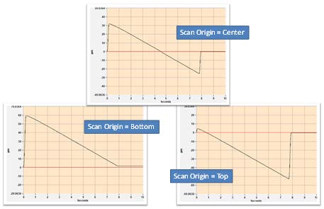
Important to note that the scanner only collects data on the downward part of the motion.
7.2: Averages, Auto Focus, and Auto Tilt
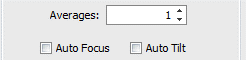
Averages - Specifies the number of measurements to average together to reduce random measurement noise. Averaging increases measurement time.
Auto Focus - Select the check box to perform auto focus before each measurement. The Auto Focus function is useful when the surface of the part being measured does not fall within the current scan range of the sensor. Auto focus will automatically scan at faster rate (depending on the controls) over a longer distance in Z (depending on the controls) to find the surface of the part, then move the sensor head so that the part surface is nominally centered in the middle of the sensor's scan range.
Auto Tilt - Select the check box to perform auto tilt before each measurement.
7.3: Signal oversampling, High Dynamic Range, and True Color
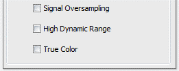
Signal Oversampling - expense of longer measurement time. Signal Oversampling is used to extract very weak signals from challenging surfaces such as those with large roughness or steep slopes. Signal Oversampling can be used in conjunction with CSI or Films measure modes and can be combined with other acquisition options such as Zip Scan, HDR, and True Color. When using oversampling and extended scan, be sure that the SureScan control is set to Off.
High Dynamic Range - Select the check box accommodate parts with a wide variation in reflectivity. This option causes the system to take sequential measurements at up to 3 discrete light levels to accommodate wide variations in part reflectivity. The two measurements are combined to maximize the amount of data and quality of the surface data produced. When the High Dynamic Range mode is checked, an HDR tab is added to the Measurement Setup panel for setting the various light levels.
True Color - Select the check box to enable the collection of a full color surface image for all data points in the topography map.
- Immediately following the metrology scan, a secondary acquisition is automatically executed to collect true color information about the surface at the point of best focus for each data point in the camera.
- Provides full color surface image for all data points in the topography map.
- To display color information in the 2D and 3D surface maps, select the True Color icon in the plot toolbar or context menu.
- Color information is stored with the .datx data file format.
Configure Stitch
The Configure Stitch Section
Stitching makes several measurements of the test part as it is moved by the motorized stage and then combines or stitches the multiple data sets into one. Effectively, it increases the field of view without compromising lateral or vertical resolution. The final graphics and results are based on the entire measured area.
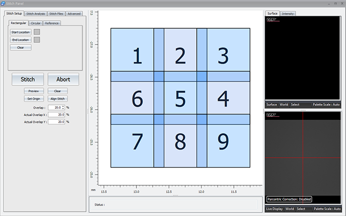
8.1: The Stitch Setup Tab
This section of the stitch panel allows the user to set up a stitch based on what they see in the live display.
The users sets the origin position (position 1). The user then sets the start and end locations. This allows the software to determine how many rows and columns are required to stitch the chosen area based on the current field of view (objective and internal magnification).
It also contains the Stitch button, controls for the size of the overlap region, and the ability to preview the area that will be scanned.
8.2: The Stitch Analysis Tab
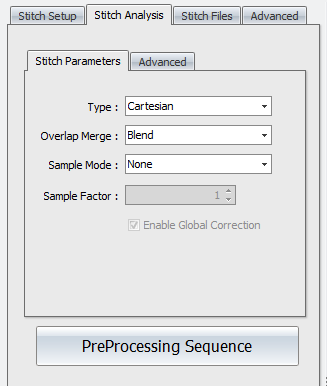
Stitch Analysis controls are used to specify how sites are aligned and how overlap areas are processed.
Stitch Analysis- Stitch Parameters
Type - Selects how sites are aligned. Options are Adjust XY, Cartesian, or Overlay. Adjust XY matches and aligns sites in x and y axes. Cartesian matches and aligns sites in x, y, z, pitch, and roll (5 axes). Overlay aligns sites based on stage coordinates.
Overlap Merge - Selects what happens in overlap regions. Options are Blend, Average, or No Merge. Blend does an interpolation (fitting) of the sites. Average averages the data in the overlap regions. No Merge does not merge overlapping areas.
Sample Mode - Selects how sites are sub sampled. This is typically used to increase throughput when stitch sequences are large (more than 100 sites). Options are None, Bin, or Skip. None means no sub sampling is performed. Bin uses a convolution of camera data and then downscales and averages data. Skip reduces the number of data points by using row and column data as determined by the Sample Factor control.
Sample Factor - Determines the functionality of the Sample Mode control. When Sample Mode is Bin, it is how many pixels get binned together. When Sample Mode is Skip, it determines the number of rows and columns of pixels to skip (or not use).
Enable Global Correction - When this check box is selected, a Cartesian algorithm is also applied after adjusting X,Y position using the Adjust XY algorithm. Only available when Type is Adjust XY.
Preprocessing Sequence - Opens a processing sequence window. This is used to specify data processing operations on the raw stitch data before it is all stitched together. See Data Processing for details on using this feature. For example, if the combined stitch area results in multiple tilted planes with nothing connecting between sites, use the remove form function in the Sequence tool.
Stitch Analysis- Advanced
Search Window - Specifies how much searching is attempted when aligning sites to each other. Too large of a search area increases processing time. Too small of an area may provide insufficient matching. The Automatic setting is determined internally and displayed. To override the Automatic setting, select the Manual radio button and enter a dimension.
Lateral Resolution - This attribute shows the lateral resolution of the current instrument configuration.
Search Window - This attribute shows the size of the search window in pixels.
8.3: The Stitch Files Tab
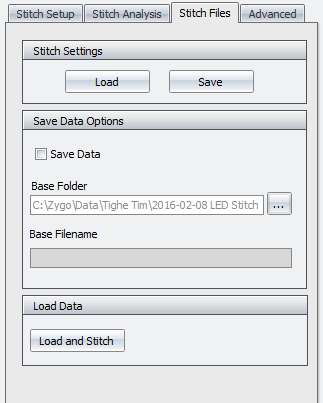
The Stitch Files tab allows the user to save the individual files of a stitch in case there is a problem during stitch. Scans which have had a problem will show up as red when completed (successful scans show up as green). If the user has saved the individual files, they can go back and just recollect the areas which had issues and then restitch the image with the software.
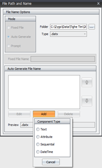
To use this feature, the user must check the Save Data option. Then click the ... button to the right of the base folder option. This will open up another dialog which allows the user to direct the software to the proper folder, add text for a filename, add sequential so you can keep track of which individual file is which, etc.
8.4: The Stitch Advanced Tab
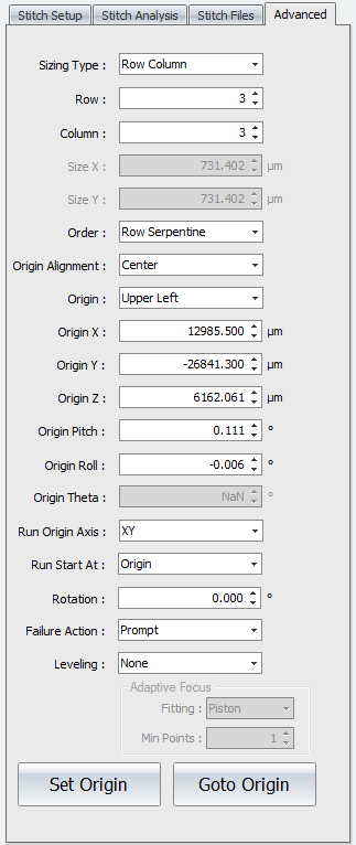
Stitch Panel Advanced Tab
Controls accessed under the Advanced tab are used to fine-tune stitch sequences.
Sizing Type - Selects how the size of the stitched area is defined. Options are Size or Row Column. Size requires lateral dimension entries in the Size X and Size Y controls. Row Column requires an entry in the corresponding Row and Column controls.
Row - Specifies the number of horizontal rows in the stitch sequence.
Column - Specifies the number of vertical columns in the stitch sequence.
Size X - Specifies the size of the overall stitched image in the x-axis.
Size Y - Specifies the size of the overall stitched image in the y-axis.
Order - Selects how to traverse the part rows and columns, in a serpentine or raster fashion. Options are Row Raster, Row Serpentine, Column Raster, or Column Serpentine. Raster order measures sites in one direction. At the end of a row or column, the stitch continues after traversing back to the beginning of the row or column. Serpentine order winds back and forth measuring sites as it goes.
Origin Alignment - Selects the site located at the origin; the field of view is aligned such that the origin stage position is either the Center or Corner.
Origin - Selects the corner where the stitch sequence begins. Options are Upper Left, Upper Right, Lower Left, or Lower Right.
Origin X - Specifies or displays the origin of the stitched image in the x-axis.
Origin Y - Specifies or displays the origin of the stitched image in the y-axis.
Origin Z - Specifies or displays the origin of the stitched image in the z-axis.
Origin Pitch - Specifies or displays the origin of the stitched image in the pitch axis.
Origin Roll - Specifies or displays the origin of the stitched image in the roll axis.
Origin Theta - Specifies or displays the origin of the stitched image in the theta axis (not applicable with PSU hardware).
Run Origin Axis - Determines the axes to move when the stitch or pattern runs and goes to the origin position. Options are XY (default) or All. XY moves only in x and y at the first site. All moves in x, y, z, pitch, and roll at the first site; all others sites only move in x, y, and z.
Run Start At - Determines where the stitch sequence or pattern is started. Options are Origin or Current Position. Origin goes to the origin and runs the stitch or pattern. Current Position sets the origin at the current site location and runs the stitch or pattern, effectively shifting the locations.
Rotation - Rotates the stitch grid. This useful when the part is skewed in reference to the instrument axes.
Failure Action - Selects the action to take if there is a measurement error during a stitch sequence. Options are Continue, Prompt, Retry, Retry After Completion. Continue ignores the error and goes to the next site. Prompt asks the user what they would like to do when a failure is encountered. Retry tries to measure the site again. Retry After Completion goes back to the sites with errors and tries again.
Leveling - Selects how to adjust in the z axis during the stitch sequence or pattern to compensate for general form in the part being measured. Options are None (default), Linear Manual Adjust, Linear Store, Tilt, Cylinder, or Adaptive Focus.