Configure Stitch
The Configure Stitch Section
Stitching makes several measurements of the test part as it is moved by the motorized stage and then combines or stitches the multiple data sets into one. Effectively, it increases the field of view without compromising lateral or vertical resolution. The final graphics and results are based on the entire measured area.
8.1: The Stitch Setup Tab
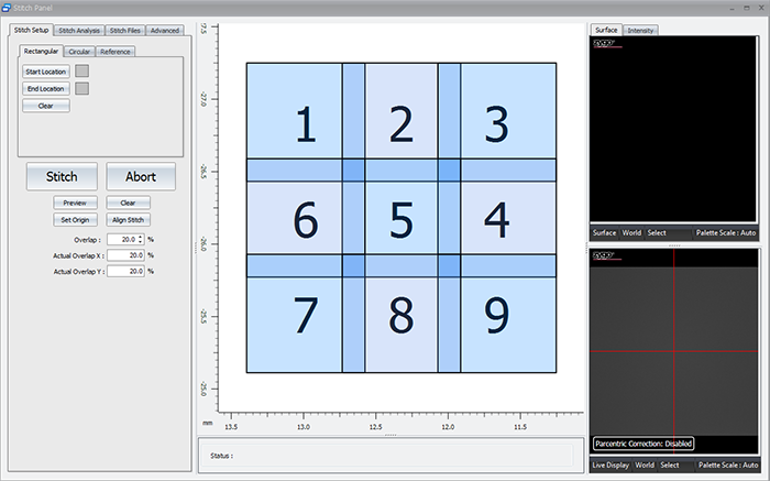
This section of the stitch panel allows the user to set up a stitch based on what they see in the live display.
The users sets the origin position (position 1). The user then sets the start and end locations. This allows the software to determine how many rows and columns are required to stitch the chosen area based on the current field of view (objective and internal magnification).
It also contains the Stitch button, controls for the size of the overlap region, and the ability to preview the area that will be scanned.
8.2: The Stitch Analysis Tab
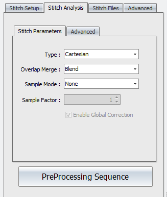
Stitch Analysis controls are used to specify how sites are aligned and how overlap areas are processed.
Stitch Analysis- Stitch Parameters
Type - Selects how sites are aligned. Options are Adjust XY, Cartesian, or Overlay. Adjust XY matches and aligns sites in x and y axes. Cartesian matches and aligns sites in x, y, z, pitch, and roll (5 axes). Overlay aligns sites based on stage coordinates.
Overlap Merge - Selects what happens in overlap regions. Options are Blend, Average, or No Merge. Blend does an interpolation (fitting) of the sites. Average averages the data in the overlap regions. No Merge does not merge overlapping areas.
Sample Mode - Selects how sites are sub sampled. This is typically used to increase throughput when stitch sequences are large (more than 100 sites). Options are None, Bin, or Skip. None means no sub sampling is performed. Bin uses a convolution of camera data and then downscales and averages data. Skip reduces the number of data points by using row and column data as determined by the Sample Factor control.
Sample Factor - Determines the functionality of the Sample Mode control. When Sample Mode is Bin, it is how many pixels get binned together. When Sample Mode is Skip, it determines the number of rows and columns of pixels to skip (or not use).
Enable Global Correction - When this check box is selected, a Cartesian algorithm is also applied after adjusting X,Y position using the Adjust XY algorithm. Only available when Type is Adjust XY.
Preprocessing Sequence - Opens a processing sequence window. This is used to specify data processing operations on the raw stitch data before it is all stitched together. See Data Processing for details on using this feature. For example, if the combined stitch area results in multiple tilted planes with nothing connecting between sites, use the remove form function in the Sequence tool.
Stitch Analysis- Advanced
Search Window - Specifies how much searching is attempted when aligning sites to each other. Too large of a search area increases processing time. Too small of an area may provide insufficient matching. The Automatic setting is determined internally and displayed. To override the Automatic setting, select the Manual radio button and enter a dimension.
Lateral Resolution - This attribute shows the lateral resolution of the current instrument configuration.
Search Window - This attribute shows the size of the search window in pixels.
8.3: The Stitch Files Tab
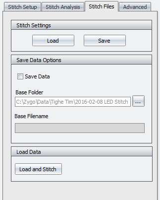
The Stitch Files tab allows the user to save the individual files of a stitch in case there is a problem during stitch. Scans which have had a problem will show up as red when completed (successful scans show up as green). If the user has saved the individual files, they can go back and just recollect the areas which had issues and then restitch the image with the software.
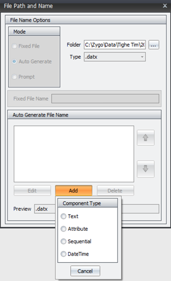
To use this feature, the user must check the Save Data option. Then click the ... button to the right of the base folder option. This will open up another dialog which allows the user to direct the software to the proper folder, add text for a filename, add sequential so you can keep track of which individual file is which, etc.
8.4: The Stitch Advanced Tab
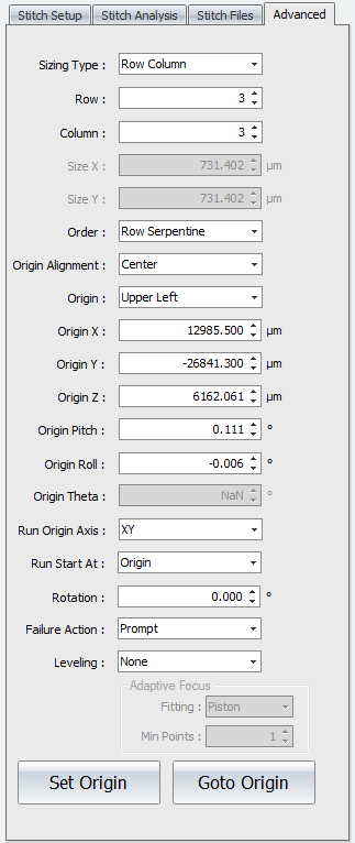
Stitch Panel Advanced Tab
Controls accessed under the Advanced tab are used to fine-tune stitch sequences.
Sizing Type - Selects how the size of the stitched area is defined. Options are Size or Row Column. Size requires lateral dimension entries in the Size X and Size Y controls. Row Column requires an entry in the corresponding Row and Column controls.
Row - Specifies the number of horizontal rows in the stitch sequence.
Column - Specifies the number of vertical columns in the stitch sequence.
Size X - Specifies the size of the overall stitched image in the x-axis.
Size Y - Specifies the size of the overall stitched image in the y-axis.
Order - Selects how to traverse the part rows and columns, in a serpentine or raster fashion. Options are Row Raster, Row Serpentine, Column Raster, or Column Serpentine. Raster order measures sites in one direction. At the end of a row or column, the stitch continues after traversing back to the beginning of the row or column. Serpentine order winds back and forth measuring sites as it goes.
Origin Alignment - Selects the site located at the origin; the field of view is aligned such that the origin stage position is either the Center or Corner.
Origin - Selects the corner where the stitch sequence begins. Options are Upper Left, Upper Right, Lower Left, or Lower Right.
Origin X - Specifies or displays the origin of the stitched image in the x-axis.
Origin Y - Specifies or displays the origin of the stitched image in the y-axis.
Origin Z - Specifies or displays the origin of the stitched image in the z-axis.
Origin Pitch - Specifies or displays the origin of the stitched image in the pitch axis.
Origin Roll - Specifies or displays the origin of the stitched image in the roll axis.
Origin Theta - Specifies or displays the origin of the stitched image in the theta axis (not applicable with PSU hardware).
Run Origin Axis - Determines the axes to move when the stitch or pattern runs and goes to the origin position. Options are XY (default) or All. XY moves only in x and y at the first site. All moves in x, y, z, pitch, and roll at the first site; all others sites only move in x, y, and z.
Run Start At - Determines where the stitch sequence or pattern is started. Options are Origin or Current Position. Origin goes to the origin and runs the stitch or pattern. Current Position sets the origin at the current site location and runs the stitch or pattern, effectively shifting the locations.
Rotation - Rotates the stitch grid. This useful when the part is skewed in reference to the instrument axes.
Failure Action - Selects the action to take if there is a measurement error during a stitch sequence. Options are Continue, Prompt, Retry, Retry After Completion. Continue ignores the error and goes to the next site. Prompt asks the user what they would like to do when a failure is encountered. Retry tries to measure the site again. Retry After Completion goes back to the sites with errors and tries again.
Leveling - Selects how to adjust in the z axis during the stitch sequence or pattern to compensate for general form in the part being measured. Options are None (default), Linear Manual Adjust, Linear Store, Tilt, Cylinder, or Adaptive Focus.