Kinematic positioning can deliver accuracies of 1 part in 100,000 to 1 part in 750,000 with relatively brief observations of only one to two minutes each. For applications that require accuracies of 1 part in 1,000,000 or higher, including control surveys and measurements of movements of the Earth's tectonic plates, static positioning is required (Van Sickle, 2001). In static GPS positioning, two or more receivers measure their positions from fixed locations over periods of 30 minutes to two hours. The receivers may be positioned up to 300 km apart. Only dual frequency, carrier phase differential receivers capable of measuring the differences in time of arrival of the civilian GPS signal (L1) and the encrypted military signal (L2) are suitable for such high-accuracy static positioning.
CORS and OPUS: The U.S. National Geodetic Survey (NGS) maintains an Online Positioning User Service (OPUS) that enables surveyors to differentially-correct static GPS measurements acquired with a single dual frequency carrier phase differential receiver after they return from the field. Users upload measurements in a standard Receiver INdependent EXchange format (RINEX) to NGS computers, which perform differential corrections by referring to three selected base stations selected from a network of continuously operating reference stations. NGS oversees two CORS networks; one consisting of its 600 base stations of its own, another a cooperative of public and private agencies that agree to share their base station data and to maintain base stations to NGS specifications.

The map above shows the distribution of the combined national and cooperative CORS networks. Notice that station symbols are colored to denote the sampling rate at which base station data are stored. After 30 days, all stations are required to store base station data only in 30-second increments. This policy limits the utility of OPUS corrections to static positioning (although the accuracy of longer kinematic observations can also be improved). Mindful of the fact that the demand for static GPS is steadily declining, NGS' future plans include streaming CORS base station data for real-time use in kinematic positioning.
Try This!
This optional activity (contributed by Chris Piburn of CompassData Inc.) will guide you through the process of differentially-correcting static GPS measurements using the NGS' Online Positioning User Service (OPUS), which refers to the Continuously Operating Reference Station network (CORS).
The context is a CompassData project that involved a carrier phase differential GPS survey in a remote study area in Alaska. The objective was to survey a set of nine ground control points (GCPs) that would later be used to orthorectify a client's satellite imagery. So remote is this area that no NGS control point was available at the time the project was carried out. The alternative was to establish a base station for the project and to fix its position precisely with reference to CORS stations in operation elsewhere in Alaska.
The project team flew by helicopter to a hilltop located centrally within the study area. With some difficulty they hammered an 18 inch #5 rebar into the rocky soil to serve as a control monument. After setting up a GPS base station receiver over the rebar, they flew off to begin data collection with their rover receiver. Thanks to favorable weather, Chris and his team collected the nine required photo-identifiable GCPs on the first day. The centrally-located base station allowed the team to minimize distances between the base and the rover, which meant they could minimize the time required to fix each GCP. At the end of the day, the team had produced five hours of GPS data at the base station and nine fifteen-minute occupations at the GCPs
As you might expect, the raw GPS data were not sufficiently accurate to meet project requirements. (The various sources of random and systematic errors that contribute to the uncertainty of GPS data are considered elsewhere in this chapter.) In particular, the monument hammered into the hilltop was unsuitable for use as a control point because the uncertainty associated with its position was too great. The project team's first step in removing positioning errors was to post-process the data using baseline processing software, which adjusts computed baseline distances (between the base station and the nine GCPs) by comparing the phase of the GPS carrier wave as it arrived simultaneously at both the base station and the rover. The next step was to fix the position of the base station precisely in relation to CORS stations operating elsewhere in Alaska.
The following steps will guide you through the process of submitting the five hours of dual frequency base station data to the U.S. National Geodetic Survey's Online Positioning User Service (OPUS), and interpreting the results. (For information about OPUS, go here)
1. Download the GPS data file. The compressed RINEX format file is approximately 6 Mb in size and will take about 1 minute to download via high-speed DSL or cable, or about 15 minutes via 56 Kbps modem. If you can't download this file, contact me right away so we can help you resolve the problem.
- WILD282u.zip (5.8 Mb)
2. Examine the RINEX file.
- Extract the RINEX file "WILD282u.05O" from its ZIP archive.
- Open "WILD282u.05O" with Microsoft Notepad or WordPad. (WordPad does a better job of preserving columns of text in this case. Set the word wrap to off.) Or, use another text editor. (In any open text editor window, in the File > Open dialog, make sure "Files of type:" is set to "All files" so that the target file is listed.)
The RINEX Observation file contains all the information about the signals that CompassData's base station receiver tracked during the Alaska survey. Explaining all the contents of the file is well beyond the scope of this activity. For now, note the lines that disclose the antenna type, approximate position of the antenna, and antenna height. You'll report these parameters to OPUS in the next step.
3. Submit GPS data to OPUS.
- Point your browser to the OPUS home page, and enter the information needed in order to "Upload your data file."
- (OPUS step 1) Click the Browse button to call up a File Upload window. Navigate to and upload the RINEX file you downloaded earlier. To streamline your submission, choose the compressed archive "WILD282u.zip".
- (OPUS step 2) Select the antenna type. Refer to the line labeled "ANT # / TYPE" in the RINEX file you opened in your text editor. You should find the antenna type "TPSHIPER_PLUS". Choose this type from the pull-down list.
- (OPUS step 3) Enter the height of the antenna above the monument. Refer to the line labeled "ANTENNA: DELTA H/E/N" in the RINEX file you opened in your text editor. The first value on that line, "1.0854", is H, in meters. (See the OPUS website for more information about antenna height.)
- (OPUS step 4) Enter the email address to which you wish your results to be returned.
- (OPUS step 5) Options. OPUS allows users to specify a State Plane Coordinate system zone, to select or exclude particular CORS reference stations, to request standard or extended output, and to establish a user profile for use with future jobs. For this activity, no changes to the default settings are needed.
- (OPUS step 6) Click the "Upload to STATIC" button to submit the data for differential correction in relation to three CORS reference stations. Depending on how many requests are in NGS' queue, results may be returned in minutes or hours. When this activity was tested, the queue included only one request (see window below, which appears after requests successfully submitted) and results were returned in just a few minutes, but in the past, it has taken up to 10 minutes.
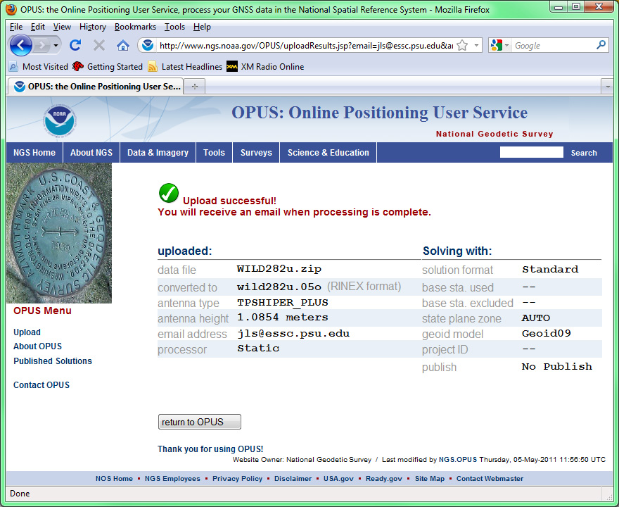 Figure 5.25.2 Upload results report.Credit: Online Positioning User Service, U.S. National Geodetic Survey.
When you receive your OPUS solution by return email, you will want to discover the magnitude of differential correction that OPUS calculated. To do this, you'll need to determine (a) the uncorrected position originally calculated by the base station, (b) the corrected position calculated by OPUS, and (c) the mark-to-mark distance between the original and corrected positions. In addition to the original RINEX file you downloaded earlier, you'll need the OPUS solution and two free software utilities provided by NGS. Links to these utilities are listed below.
4. Determine the position of the base station receiver prior to differential correction.
- Refer to the RINEX file "WILD282u.05O" you opened in your text editor. The ninth line of the RINEX file lists the position of the base station receiver in Earth-Centered Earth-Fixed X, Y, Z coordinates. This is a three-dimensional Cartesian coordinate system whose origin is the Earth's center of mass (like the NAD 83 datum).
-2389892.2740 -1608765.8567 5672855.7386 APPROX POSITION XYZ
NGS provides a conversion utility to transform these X, Y, Z values to more familiar latitude and longitude coordinates and ellipsoidal heights. - Go to NGS' XYZ to GEODETIC conversion.
- Enter the X, Y, Z coordinates found in the RINEX file. Your result should be:
- Latitude = 63°13'53.74280" N
- Longitude = 146°03'12.12710" W
- Height = 1349.2248 m
5. Determine the corrected position of the base station receiver. The OPUS solution you receive by email reports corrected coordinates in Earth-Centered Earth-Fixed X, Y, Z as geographic coordinates, and as UTM and State Plane coordinates. Look for the latitude and longitude coordinates and ellipsoidal height that are specified relative to the NAD 83 datum. They should be very close to:
- Latitude = 63°13'53.73892" N
- Longitude = 146°03'11.98942" W
- Height = 1348.756 m
6. Calculate the difference between the original and corrected base station positions. NGS provides another software utility to calculate the three-dimensional distance between two positions. Unlike the previous XYZ to GEODETIC converter, however, the "invers3d.exe" is a program you download to your computer.
- Download "invers3d.exe"
- Double-click on the file name to run the program, and choose the geodetic coordinates option.
- Paying close attention to the required formats, enter the uncorrected latitude, longitude, and ellipsoidal heights you calculated in step 4 above.
- Next, choose the geodetic coordinates option again and enter the corrected coordinates and height you calculated in step 5.
- Among the results, look for the calculated "mark-to-mark distance." This is the magnitude of the OPUS correction.