Lesson 9: Drilling Engineering: Drilling Rig Systems and the Drilling Process
9.0: Lesson Overview
In this lesson, we will continue discussing the drilling of oil and gas wells. In particular, we will discusst the major systems and sub-systems of modern rotary drilling rigs including their roles in the drilling process.
Learning Objectives
By the end of this lesson, you should be able to:
- describe and discuss the five major systems of a drilling rig:
- the Power System,
- the Hoisting System,
- the Circulation System,
- the Rotary System, and
- the Well Control System (Blowout Prevention System);
- discuss the role of these systems in the drilling of oil and gas wells;
- list the sub-systems that comprise these five major systems;
- describe the important sub-systems on the drilling rig;
- discuss the drilling process and how rig activities and systems interact during this process
Lesson 9 Checklist
| To Read | Read the Lesson 9 online material | Click the Introduction link below to continue reading the Lesson 9 material |
|---|---|---|
| To Do | Lesson 9 Quiz | Take the Lesson 9 Quiz in Canvas |
Please refer to the Calendar in Canvas for specific time frames and due dates.
Questions?
If you have questions, please feel free to post them to the Course Q&A Discussion Board in Canvas. While you are there, feel free to post your own responses if you, too, are able to help a classmate.
9.1: Introduction
In the last lesson, we learned about Rig Contracts, the Rig Crew, and Different Drilling Rigs. In this lesson, we will continue our discussions of the drilling rig and start a discussion on the drilling process. In Lesson 8, we saw that there are different onshore and offshore drilling rigs. While these rigs have different applications and there are pros and cons for each, there are many similarities. We will continue our discussion on drilling rigs with these similarities.
9.2: Major Systems on a Drilling Rig
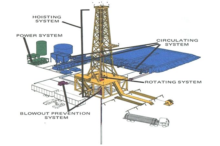
While there are different types of drilling rigs, these rigs obviously share many similarities since the tasks that they perform are identical. In particular, all modern hydrocarbon rotary rigs contain five main systems. These systems are:
- the Power System
- the Hoisting System
- the Rotary System
- the Circulation System
- the Well Control System (Blowout Prevention System)
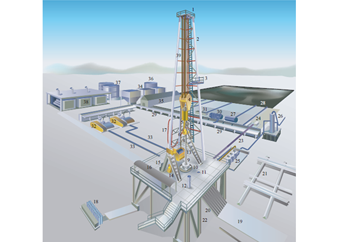
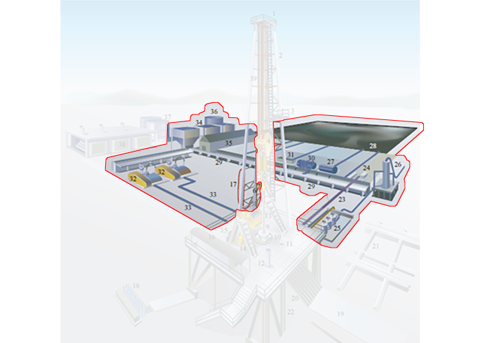
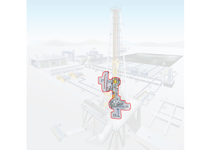
These systems are shown in Figure 9.01. In addition, Figure 9.02 shows a more detailed schematic diagram of a rotary table, land rig.
 |
||
|
|
|
| Source: Serintel: Oil and Gas Portal - Drilling Technologies [1] | ||
9.2.1: The Power System
The power system on a drilling rig provides the power for the other main systems on the rig and other ancillary systems, such as electrical systems, pumps, etc. The system typically consists of a prime mover (the component of the power system that generates the raw power) and a means to transmit the raw power to the end-use components on the rig.
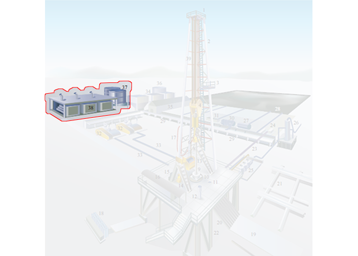
In the detailed rig schematic (Figure 9.02a), the power system is comprised of:
- the Fuel Storage (Item 37)
- the Engines and Generators (Item 38)
Historically, coal was used to generate the power for drilling rigs; however, modern drilling rigs use other sources of fuel. Typically, modern rigs are now run using an internal combustion engine with diesel or lease fuel. Diesel oil is a petroleum-based fuel that is a product of the distillation process. If the rig is running in a developed field, then the field may have a small on-site refinery that is used to distill the diesel fuel. If the rig is drilling an exploration, appraisal, or delineation well, then the fuel will need to be delivered from an external source and stored on-site.
Lease fuel is typically produced natural gas. As we have learned, natural gas is always produced along with crude oil. Again, if the rig is drilling wells in a developed field, then the field may use the natural gas or Natural Gas Liquids (NGL) to fuel the prime mover. This natural gas may be processed to remove NGLs if a gas plant is available on site; may need to burn these hydrocarbon liquids (possible sales product) if a gas plant is unavailable; or may burn the processed NGLs (butane).
The transmission of the power can be:
- mechanical
- direct current (DC) electrical generator
- alternating current (AC) electrical generator with silicon-controlled rectifier (SCR) to direct current (DC)
In the mechanical transmission, power is generated with the prime mover and is transmitted to the end-use components by the application of chains and sprockets (similar to a bicycle), drive belts, drive shafts, etc. In a direct current (DC) electrical system, an internal combustion engine operates an electrical generator (in this case a DC generator) and the electrical energy is transmitted to the motors, electrical actuators, etc. Finally, in an alternating current (AC) electrical system, an internal combustion engine operates an electrical generator (in this case an AC generator) which is converted to DC with a silicon-controlled rectifier (SCR). AC-SCR power systems are the most widely used power systems on modern drilling rigs.
9.2.2: The Hoisting System
The hoisting system on a drilling rig does the heavy lifting on the rig. It is used to raise, lower, and suspend the drill string and lift casing and tubing for installation into the well.
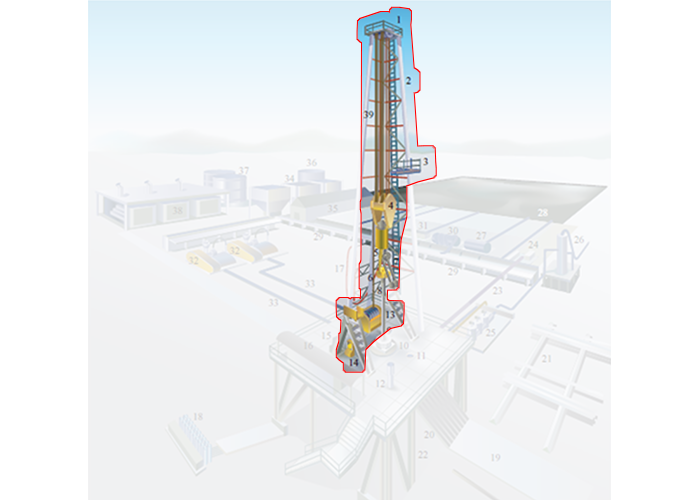
In the detailed rig schematic (Figure 9.02b) the hoisting system is comprised of:
- the Crown Block (Item 1)
- the Mast/Derrick (Item 2)
- the Monkey Board (Item 3)
- the Traveling Block (Item 4)
- the Hook (Item 5)
- the Swivel (Item 6)
- the Drawworks (Item 13)
- the Weight Indicator (Item 14)
- the Drilling Line (Item 39)
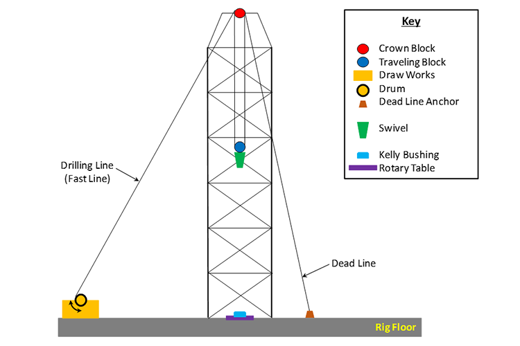
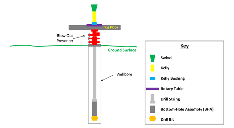
A schematic of the hoisting system is shown in Figure 9.03 for a kelly drive rig. In this figure, the derrick (or mast) provides the structural support for the hoist system. It must be capable of supporting the entire load on the system including the weight of the drill string (accounting for buoyancy effects) and any frictional forces.
The crown block and the traveling block form a Block and Tackle System on the rig. The drill line can be strung as pairs of 2 through 12 lines (six pairs). The greater the number of lines (and pulleys) in the block and tackle system, the greater its lifting power but at the expense of slower upward and downward movement of the system.
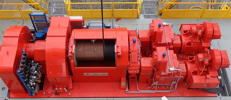
The drawworks of the hoisting system is a winch that reels the drilling line in or out causing the traveling block to move up or down. The drawworks is the component of the hoisting system that consumes energy from the power system. The drum on the drawworks is grooved to accommodate a specific size drilling line. Figure 9.04 shows a photo of an actual drawworks used on a drilling rig .
Not shown on the schematic or the photo is the braking system on the drawworks. Modern rigs use both a mechanical brake and an electromagnetic brake. The braking system is an integral part of the drilling process because it is used to control the Weight-on-Bit (WOB) during drilling. The two most important drilling parameters within the Driller‘s control to maximize the Rate of Penetration (ROP) are the weight-on-bit and the rotational speed of the rotary system in Revolutions per Minute (RPM).
The weight-on-bit is achieved with the weight of the drill pipe and Drill Collars, however the optimum weight-on-bit is often less than the total weight of the drill string. The brake is used to take up some of the weight of the drill string, so that the weight-on-bit is only a fraction of the total weight.
Also shown in Figure 9.03 is the Swivel. The swivel is the link that connects the hoisting system to the rotary system and to the circulation system. The function of the swivel is to:
- hold the weight of the drill string on the hoisting system (the hoisting system does not rotate);
- allow rotation of the drill string below it (the drill string, Bottom-Hole Assembly (BHA), and drill bit all rotate);
- allow passage of the drilling fluid from the circulation system (non-rotating) to the drill string, Bottom-Hole Assembly (BHA), and drill bit of the rotary system.
9.2.3: The Circulation System
The circulation system on the rig is the system that allows for circulation of the Drilling Fluid or Mud down through the hollow drill string and up through the annular space between the drill string and wellbore. It is a continuous system of pumps, distribution lines, storage tanks, storage pits, and cleansing units that allows the drilling fluid to fulfill its primary objectives (these will be discussed later in this lesson). The mud pumps of the circulation system and the drawworks of the hoisting systems are the two largest draws on the power from the power system
In the detailed rig schematic (Figure 9.02c), the circulation system is comprised of:
- the Swivel (Item 6)
- the Rotary Hose (Item 17)
- the Mud Return Line (Item 23)
- the Shale Shaker (Item 24)
- the Choke Manifold (Item 25)
- the Mud Gas Separator (Item 26)
- the Degasser (Item 27)
- the Reserve Pit (Item 28)
- the Mud Pits (Item 29)
- the Desander (Item 30)
- the Desilter (Item 31)
- the Mud Pumps (Item 32)
- the Mud Discharge Line (Item 33)
- the Bulk Mud Components Storage (Item 34)
- the Mud House (Item 35)
- the Water Tank (Item 36)
Drilling fluid is mixed in the mud pits and pumped by the mud pumps through the swivel, through the blow out preventer (not part of the circulation system) down the hollow drill pipe, through holes (Jet Nozzles) in the bit, up the annular space between drill pipe and wellbore (where it lifts the rock cuttings), to the surface, through the Solids Control Equipment (Shale Shaker, Desander, and Desilter), and back to the mud pits. A schematic of the circulation system is shown in Figure 9.05.
In this figure, fresh water-based drilling fluid (mud) is mixed with water from the Water Tank (not shown in Figure 9.05) and components from the Bulk Mud Components Storage (not shown in Figure 9.05) in the Mud Pit. The Mud Pumps then pump the mud through the swivel, kelly, kelly bushing, and rotary table down to the drill string.
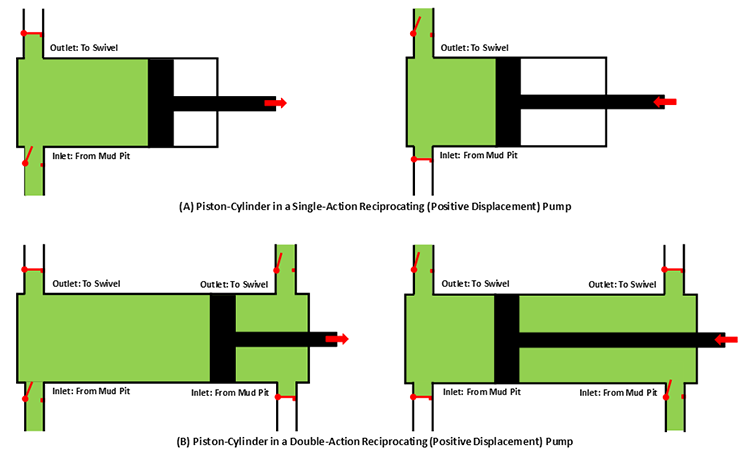
The mud pumps on a typical drilling rig are either single-action or double-action Reciprocating (Positive Displacement) Pumps which may contain two pistons-cylinders (duplex pump) or three pistons-cylinders (triplex pump). Figure 9.06 shows schematics of a single piston-cylinder in (A) a single-action and (B) a double-action reciprocating pump.
In these pumps, the positive pressure and negative pressure (suction) in the cylinder cause the valves to open and close (note: the valves in the schematic are simple representations of the actual valves). Due to the high viscosity of the drilling fluid, the inlet side of the pump may require a Charge Pump to keep fluids moving into the cylinders at high pressures and to prevent Cavitation in the pump.
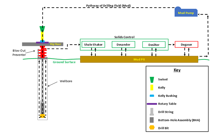
From the mud pumps, the drilling fluid goes to the swivel, through the blow out preventer, and down the hollow drill string and bottom-hole assembly. The drilling fluid then goes through jet nozzles in the drill bit; at which point, it begins its return to the surface. The drilling fluid travels up the annular space between the drill pipe and the wellbore, picking up and carrying the drill cuttings up the hole.
Once the drilling fluid reaches the surface, it goes through the mud return line to the gas-mud separator and the solids control equipment. The shale shaker is where the large cuttings from the returning drilling fluid are removed. The shale shaker is a set of vibrating mesh screens that allow the mud to pass through while filtering out cuttings of different size at screen screen mesh sizes. A Mudlogger or a Well-Site Geologist may be stationed at the shale shaker to analyze the cuttings to determine the lithology of the rock and the depth within the Stratigraphic Column at which the well is currently being drilled.
The drilling fluid then passes through the Desander and Desilter. These are hydrocyclones which use centrifugal forces to separate the smaller solids from the drilling fluid. The desander typically removes solids with a diameter in the range of 45 – 74 μm, while the desilter removes solids with a diameter in the range of 15 – 44 μm.
The drilling fluid is then sent through a degasser to remove any gas bubbles that have been picked up during the circulation. These gasses may include natural gas from the subsurface or air acquired during the solids control. Typically, the degasser is a piece of equipment that subjects the drilling fluid to slight vacuum to cause the gas to expand for extraction. The drilling fluid is then returned to the mud pit to start the circulation process over again.
We have discussed the mechanics of how the drilling fluid is circulated during the drilling process, but we have not discussed the role of the drilling fluid. The term “mud” is often used in oil and gas well drilling because historically the most common water-based drilling fluids were mixtures of water and finely ground, bentonite clays which, in fact, are muds.
There are many objectives for using a drilling fluid. These include:
- lift drill cuttings from the bottom of the wellbore to the surface;
- suspend cuttings to prevent them from falling downhole if circulation is temporarily ceased;
- release the cuttings when they are brought to the surface;
- stabilize the borehole during drilling operations (exert hydrostatic or hydrodynamic pressure on the borehole to prevent rock caving into the wellbore);
- control formation pore pressures to assure desired well control (apply hydrostatic and hydrodynamic pressures in excess of the formation pore pressures to prevent fluids from entering the wellbore);
- deposit an impermeable filter cake onto the wellbore walls to further prevent fluids from permeable formations from entering the wellbore;
- minimize reservoir damage (assure low skin values) when drilling through the reservoir section of the well;
- cool the drill bit during drilling operations;
- lubricate the drill bit during drilling operations;
- allow for pressure signals from Logging While Drilling (LWD) or Measurement While Drilling (MWD) tools to be transmitted to the surface (LWD and MWD data are transmitted to the surface using pressure pulses in the drilling fluid);
- allow for pressure signals to be sent to the bottom of the well to pressure actuate certain downhole equipment;
- minimize environmental impact on subsurface natural aquifers.
As I stated earlier, historically drilling fluids were mixtures of bentonite clay, water, and certain additives to manipulate the properties of the mud (density, viscosity, fluid loss properties, gelling qualities, etc.). Today, there are several different options available for drilling fluids. These include:
- water-based muds (WBM)
- oil-based muds (OBM)
- foams
- air
Of the listed drilling fluids, the water-based muds and the oil-based muds are the most common; foam drilling and air drilling can only be used under specialized conditions. Of the two liquid based mud systems (water-based muds and oil-based muds), water-based muds are the most common mud system. They are more environmentally friendly and are used almost exclusively to drill the shallow portions of the well where fresh water aquifers exist to minimize any contamination to those aquifers. As this implies, drilling fluids can be – and often are – switched during the course of drilling operations in single well.
In addition, water-based muds are cheaper than oil-based muds, so they are used to reduce drilling costs and commonly represent the “default” selection for a drilling fluid. In other words, water-based muds are often used unless there is a specific reason to switch to an oil-based mud.
Oil-based muds are formulated with diesel oil, mineral oil, or synthetic oils as a continuous phase and water as a dispersed phase in an emulsion. In addition, additives such as emulsifiers and gelling agents are also used. They were specifically developed to address certain drilling problems encountered with water-based muds. The reasons for using an oil-based mud include:
- drilling through shales that are susceptible to swelling (in particular, highly smectite-rich shales). Shales contain a large amount of clay material and when these clays come in contact with the water in a water-based mud system, the clays may swell causing the shales to collapse into the hole. Smectite-rich shale formations are often referred to as “Gumbo” or “Gumbo Clays” in the drilling industry;
- reducing torque and drag problems in deviated wells. Since oil, a lubricant, is the continuous phase in the mud system, the torque and drag between the drill pipe and the wellbore is reduced with oil-based muds;
- achieving greater thermal stability at greater depths. Oil-based muds have been found to retain their stability (retain their desired properties) at greater down hole temperatures;
- achieving greater resistance to chemical contamination. Many substances found down-hole (salt, CO2, H2S, etc.) are soluble in water. The introduction of these substances into the water-based mud system may have a deleterious impact on different mud properties (density, viscosity, fluid loss properties, gelling properties, etc.). These substances are not soluble in oil and, therefore, have will not impact oil-based mud properties.
The first three bullet points in this list are becoming more common problems in the oil and gas industry. The shale boom in the U.S. has made long horizontal sections in shale reservoirs targets for drilling. In addition, deviated wells and deeper wells are also becoming more common. For these reasons, the use of oil-based muds is also becoming more common.
There are also several disadvantages with oil-based muds. These include:
- high initial costs. Often in an active drilling campaign, if certain depth intervals require an oil-based mud, the mud is stored and reused in different wells;
- slow rates of penetration. Historically, the rate of penetration has been statistically slower for oil-based muds than it is for water-based muds. The rate of penetration is the speed at which the drilling process progresses (depth versus time) and is a function of many factors other than mud type, including: weight on bit, RPM, lithologies being drilled through, bit type, bit wear, etc.;
- environmental concerns:
- oil contamination of subsurface fresh water aquifers,
- cleaning and disposal of oil contaminated rock cuttings;
- kick detection. If gas enters the wellbore (a Kick), it may go into solution in the oil in deeper, higher pressure sections of the well and come out of solution closer to the surface;
- formation evaluation. Some readings from well logs or core analysis may be sensitive to oil entering the formation of interest (for example, if oil from the oil-based mud enters the reservoir in the near-well vicinity, then tools used to detect oil saturation may read artificially high).
Other drilling fluids currently in use that were listed earlier are foams and air. In the context of drilling fluids, foams have the consistency of shaving cream. Both foam and air drilling are used in hard rock regions, such as in the Rocky Mountains, where drill bits render the drill cuttings to dust. Thus, the foam or air only needs to lift this dust to the surface. Air drilling is always an environmentally friendly option if it is applicable because environmental contamination by air is never an issue.
9.2.4: The Rotary System
The rotary system on a drilling rig is the system that causes the drill bit rotate at the bottom of wellbore. We have discussed some components of the rotary system when we discussed rotary table and top-drive rigs, but we have not yet discussed the entire system.
In the detailed rig schematic (Figure 9.02d), the rotary system is comprised of:
- the Swivel (Item 6)
- the Kelly (Item 8) – the functionality on a top-drive rig is handled by the top-drive
- the Kelly Bushing (Item 9) – the functionality on a top-drive rig is handled by the top-drive
- the Master Bushing (Item 10) – the functionality on a top-drive rig is handled by the top-drive
- the Rotary Table (not shown in Figure 9.02d) – the functionality on a top-drive rig is handled by the top-drive
- the Mousehole (Item 11) – used to connect single joints on a top-drive or rotary table rig
- the Rat Hole (Item 12)
- the Rotary Hose (Item 17)
- the Drill String (not shown in Figure 9.02d)
- the Bottom-Hole Assembly (not shown in Figure 9.02d)
- the Drill Bit (not shown in Figure 9.02d)
A schematic of the rotary system is shown in Figure 9.07. As we can see in Figure 9.07, the rotary system shares many components with the circulation system. This is because in the rotary system, these components rotate in support of causing the bit to rotate, while in the circulation system, these components act as conduits for the drilling fluid.
In Lesson 8, we saw that the rotary table imparted the torque for the drill string in a conventional rotary table rig, while the top-drive imparted this torque on a top-drive rig. We also saw that drill pipe was added to the drill string one joint at a time on a rotatory table rig, while a top-drive could add multiple joints of drill pipe during one connection operation.
The Bottom-Hole Assembly is comprised of any bottom hole equipment required to drill the current section of the well. A bottom-hole assembly may be as simple as a Drilling Collar. Drill collars are sections of heavy, thick walled pipe used to add weight-on-bit to the drill string. More complicated bottom-hole assemblies may include Jars, downhole directional steering and positioning equipment, logging-while-drilling, and measure-while-drilling equipment.
Jars are mechanical devices that deliver a transfer of kinetic energy to another piece of downhole equipment as the result of an impact. They are typically used to loosen a piece of downhole equipment with an impact (jarring action). You can think of a jar as comparable to a hammer used to loosen two boards that are nailed together by hitting one of the boards in the direction opposite of the head of the nail.
At the end of the drill string and bottom-hole assembly is the drill bit. There are many types of drill bits, but we will focus on two types of drilling bits, the Tri-Cone (or Roller Cone) Bit and Fixed-Cutter Bit. In addition, we will be discussing two variants of the tri-cone bit: the milled-tooth bit and the insert bit. All of these bits can be classified as in the following bullet list:
- tri-cone bits
- milled-tooth bits
- insert bits
- fixed-cutter bits
Tri-cone bits are the most common drilling bits and, historically, have been the workhorse of the drilling industry. As the name implies, tri-cone bits contain three cones, each of which contain cutting teeth.
The two-cone bit (an early version of the tri-cone bit) was invented by Howard Hughes Jr.’s father (Howard Sr.). The tri-cone bit and the formation of the Hughes Tool Co. (now part of Baker-Hughes, a subsidiary of the General Electric Corporation) was the source of the Hughes family wealth. In case you do not know who Howard Hughes Jr. was, he was an award winning pilot in the 1920s and 1930s (holder of several aerial speed records and subject of the movie “The Aviator”), a filmmaker (had controlling interest of RKO Studios and actively produced several notable silent and early “talkie” films), airplane designer (owner of Hughes Aircraft – contractor for the world’s largest wooden airplane, “The Spruce Goose,” with Howard as its only pilot in 1947), and a billionaire by the 1970s and 1980s (back when a billion dollars had some value).
In a milled-tooth bit, the teeth of the bit are machine-milled along with the rest of the cone. The cones of the tri-cone bit, including the teeth, are formed from a single, solid piece of steel. An example of a milled-tooth bit is shown in Figure 9.08.
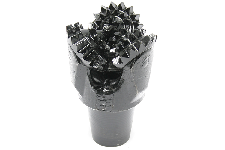
In this figure, we can see that the teeth of the bit are intrinsic parts of the cones; they are milled from the same piece of steel. These bits, as do all tri-cone bits, drill through the rock by exerting the full weight-on-bit on only a few contact points (the sharpened teeth) between the bit and the rock. This exerts extremely high levels of stress at the contact points causing the rock to fail catastrophically (almost explosively). We will see this in a YouTube video later in the lesson.
One design feature of the tri-cone bit is the interaction of the teeth on the different cones helping to remove any small cuttings or sticky shales/clays (Gumbo Shales) that may get lodged between the teeth and reduce the efficiency of the bit. This phenomenon of cuttings and clays getting lodged between bit teeth is referred to as Bit Balling and results in slower Rates-of-Penetration (ROP) of the drilling process. The self-cleaning action of the teeth in a tri-cone bit is designed to reduce the bit balling.
Milled-tooth tri-cone bits are mainly used for drilling through soft rock formations. This is because, no matter how strong the steel used in the construction of the cone, hard rock can cause excessive wear and degradation of the teeth.
Insert drill bits, on the other hand, are bits in which the teeth are made from materials stronger than the steel used in the cone and are inserted into cone. Example of insert tri-cone bits are shown in Figure 9.09.
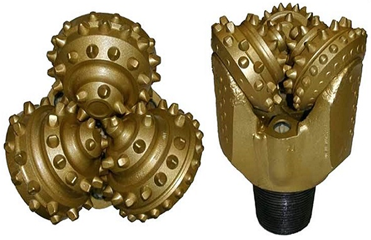
While the insert bit shown in Figure 9.09 may superficially look like the milled-tooth bit; careful inspection reveals that the teeth in the insert bit are not milled but are inserted into the cone. Typically, the teeth in an insert bit are made from tungsten-carbide steel (Tungsten Carbide Insert bit or TCI bit) which is a much stronger alloy of steel than the alloys used for the cones. Other design features included on insert bits include the length and the shape of the teeth (short, round-shaped teeth for hard rock formations or long, chisel-shaped teeth soft formations). These designs allow for a range of lithologies for these bits to be used: in hard rock formations that would be inappropriate for milled-tooth bits or in soft rock formations for extended bit-life.
While the insert bit helps to alleviate the issues with tooth-wear, there is an additional source of wear that can shorten the life of a drilling bit. Due to the moving parts associated with a tri-cone (or roller) bit, the bit requires a bearing where the moving parts meet and move past one another. Thus, the wear on the bearings may also shorten the life of the bit.
Fixed cutter bits are bits that do not contain any moving parts. These bits are designed to drill by shearing and scraping the rock formations as opposed to the gouging action used by a tri-cone bit. These bits typically use industrially made diamonds for the teeth and are also known as Polycrystalline Diamond Compact (PDC) bits. Figure 9.10 shows an example of a PDC bit.
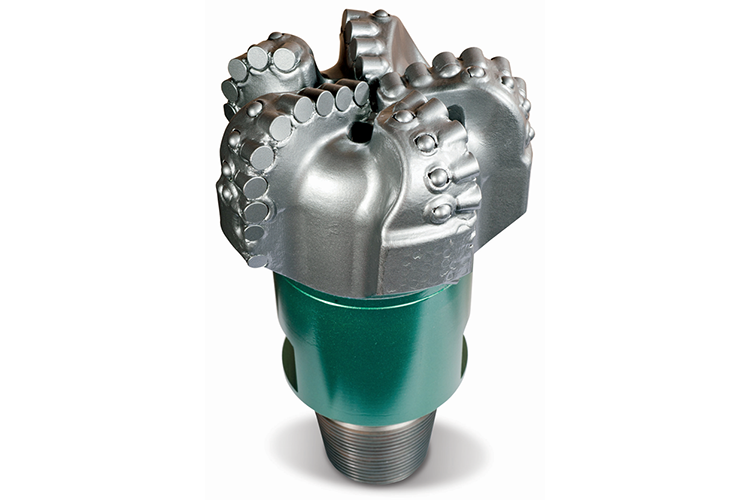
The PDC bits are used to drill through very hard rock formations or for extended bit-life drilling. These bits have a large initial cost but because of the hard teeth and lack of any moving parts have a longer bit-life. One recent innovation for PDC bits in geologic basins with many shallow (short-footage) drill sites is the ability to rent the drill bit from the drilling company rather than to purchase it from a tool company. This innovation allows for an operating company to rent the bit and to use it for the footage that they require before relinquishing it to another operating company.
We have discussed that the tri-cone bits and the fixed cutter bits have different drilling actions. Here is a YouTube video, "Drill Bits - Oil and Gas Drilling: From Planning to Production" (3:26), that demonstrates the differences of the explosive, gouging, and crushing action of the tri-cone bit and the scraping action of the fixed cutter bits:
While we're out of the hole the operator also wants to switch to a track hone bit. This style of bid is less aggressive than a PDC and will drill a little slower. Bit selection is very important part of drilling a well so let's go review that now.
While we're out of the hole the operator also wants to switch to a track hone bit. This style of bid is less aggressive than a PDC and will drill a little slower. Bit selection is very important part of drilling a well so let's go review that now.
There are two basic categories of drill bits roller cone bits and fixed cutter bits.
Roller cone bits have cones that roll is the bit turns and projections in the cones gouge, scrape, and crush rock as they roll. Most roller cone bits have three cones and are called tri cone bits.
There are two basic types of roller cone bits millled tooth bits and tungsten carbide insert bits. Milled tooth bits also called steel toothed bits use steel teeth to gouge through rock. Milled toothed bits are best in softer formations and are generally less expensive than other types of bits.
Tungsten carbide insert, or TCI bits, have tungsten carbide treated inserts that gouge, chip, and crush rock. Tungsten carbide is one of the hardest materials known and TCI bits are capable of drilling some of the hardest and most abrasive formations. Tungsten carbide inserts come in a variety of shapes and because of their appearance TCI bits are often called button bits.
Fixed cutter bits do not have moving parts and they work primarily by shearing and scraping through rock. Fixed cutter bits include polycrystalline diamond compact bits, natural diamond bits, and impregnated bits.
Polycrystalline diamond compact, or PDC bits, have tungsten carbide cutters topped with hard caps of diamond composite material. The cutters are angled and arranged to shear channels in the rock. The diamond caps are made by heating and compressing artificial diamond grit with tungsten carbide and other metallic binders. PDC bits come in a variety of designs that can be used for an extensive range of drilling requirements. PDC bits are much more expensive than roller cone bits but can generally penetrate faster and last longer than roller cone bits which saves drilling costs.
Natural diamond bits have industrial grade diamonds set in the bit surface to create an abrasive cutting face. They are primarily used in hard or highly abrasive formations that would be more damaging to other bit types. They are not as effective in softer formations because of their smoother surface profile.
Diamond impregnated bits have PDC cutters protruding straight out of the bit body whereas regular PDC bits have cutters bonded to the outside at an angle to the cutting face. The impregnated design increases cutter stability and the lateral cutting angle keeps cutters sharp as they wear. Diamond impregnated bits are good informations with intermittent layers of soft and hard rock because they can effectively cut through both.
There are many other types of specialty bits including bits for coring, sidetracking, reaming, and other applications.
9.2.5: The Well Control System (Blowout Prevention System)
The Well Control System or the Blowout Prevention System on a drilling rig is the system that prevents the uncontrolled, catastrophic release of high-pressure fluids (oil, gas, or salt water) from subsurface formations. These uncontrolled releases of formation fluids are referred to as Blowouts. Due to the explosive nature of oil and gas, any spark on the surface can result in the ignition of the fluids and an explosion on the rig. An explosive blowout and the failure of the Well Control System were the causes of the Mocondo Well disaster that killed eleven of the rig crew on the Deep Water Horizon Rig on April 20, 2010 and resulted in 35,000 to 60,000 bbl/day of crude oil to spill into the Gulf of Mexico. We will discuss this later in the lesson.
In the detailed rig schematic (Figure 9.02e), the well control system is comprised of:
- the Accumulator (Item 18)
- the Blowout Preventer (not shown in Figure 9.02e)
A picture of a Blowout Preventer (BOP), pronounced “B-O-P” not “bop”, is shown in Figure 9.11.
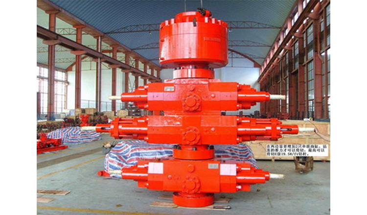
The blowout preventers are the principal piece of equipment in the well control system and are operated hydraulically; pressurized fluids are used to operate pistons and cylinders to open or close the valves on the BOP. The Accumulators (Item 18 in Figure 9.02) are used to store pressurized, non-explosive gas and pressurized hydraulic fluid to run the hydraulics systems on the rig. The accumulators store enough compressed energy to operate the blowout preventers even if the Power System of the rig is not operating.
The blowout preventer is a large system of valves each of which is capable of isolating the subsurface of the well from the rig to provide control over the well. These valves are typically stacked as shown in the Figure 9.11 and sit below the rig floor on land wells or some offshore wells; or they may sit on the seabed on other offshore wells.
A schematic diagram of a blowout preventer is shown in Figure 9.12.
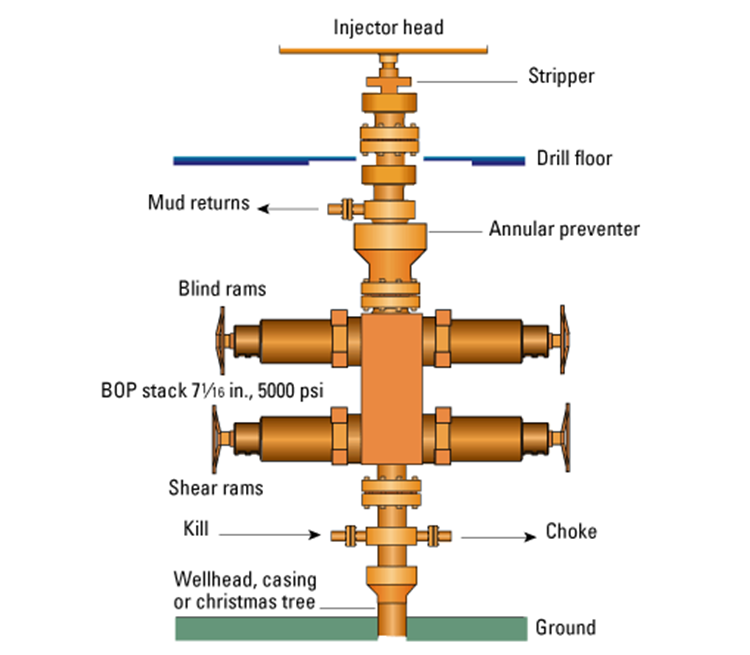
Figure 9.12 shows three type of valves (there are others) – an Annular Preventer, Blind Rams, and Shear Rams. The Annular preventer is the ring-shaped piece of equipment on the top of the BOP in Figure 9.11. As the name implies, the annular preventer is used to prevent flow through the annular space between the drill string or casing and the annular preventer. The annular preventer can also be used for non-cylindrical pipe, such as the kelly, or open hole. The annular preventer consists of a doughnut shaped bladder that when in the open position allows the drill pipe to rotate but in the closed position seals the annulus. Figure 9.13 provides a schematic of the annular preventer.
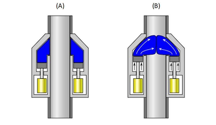
In Figure 9.13, the blue area represents the doughnut-shaped bladder. As mentioned earlier, in the open position, (A), the drill pipe can be rotated or can be run up or down; while in the closed position, (B), the bladder pushes out, closing off the drill pipe, kelly, or open hole. The bladder based sealing element is not as effective as the ram type sealing elements; however, almost all blowout preventer stacks include at least one annular preventer.
Schematics of the ram-type preventers: the blind rams, the shear rams, and the pipe rams (pipe rams are not shown in Figure 9.12) are shown in Figure 9.14.
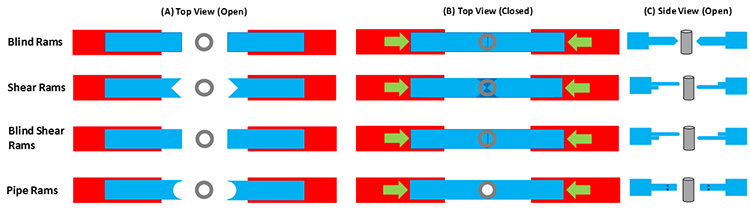
This figure shows that:
- blind rams isolate both the pipe and the annular space by crushing the pipe and it pinching-off when closed;
- shear rams isolate both the pipe and the annular space by shearing-off the pipe when closed;
- blind shear rams isolate both the pipe and the annular space by shearing-off and crushing the pipe when closed;
- pipe rams isolate the annular space by wrapping around the pipe when closed.
A blowout begins as a Kick (entry of subsurface formation fluids into the wellbore). What distinguishes a kick from a blowout is that a kick can be controlled while a blowout is uncontrollable. We have already discussed two of the defenses against kicks when we discussed drilling fluids when we listed the objectives of the drilling fluid:
- control formation pore pressures to assure desired well control (apply hydrostatic and hydrodynamic pressures in excess of the formation pore pressures to prevent fluids from entering the wellbore);
- deposit an impermeable filter cake onto the wellbore walls to further prevent fluids from permeable formations from entering the wellbore.
In the first objective re-quoted above, if we can keep the pressure exerted by the drilling mud greater than the pore pressure, then we know that fluids will flow in the direction of the mud to the formation. This cannot always be achieved. For example, if we drill through a natural fracture or if our mud density is too great and we inadvertently fracture one formation, then we may lose large quantities of the drilling fluid into the fracture (Lost Circulation). In this situation, instead of having the full weight of the mud column exerting pressure on a second (porous and permeable) formation, we may only have a fraction of the oil column height exerting a lower pressure on that second formation.
In the second objective re-quoted above, if we deposit an impermeable Drill Cake (filter cake) across an otherwise porous and permeable formation, then for a slightly Underbalanced Pressure (drilling fluid pressure lower than the formation pressure) we have created a seal between the wellbore and the formation. Again, this is not a Failsafe System because at greater underbalanced pressures, the higher formation pressures may be able to displace the drill cake.
The two previously discussed methods are used to help prevent a kick from occurring, but as mentioned they are not always successful, and kicks may still occur. The causes of a kick include:
- insufficient mud weight (density): the hydrostatic pressure exerted by the mud column is not greater than the formation pore pressure;
- improper mud replacement during tripping: while tripping out of the hole mud volumes must be pumped into the wellbore at high enough rates to replace drill pipe being removed from the wellbore;
- swabbing: removing drill pipe from the wellbore can create a negative pressure (suction) if the drill pipe is removed too quickly;
- cut mud: if gas is entering the wellbore, then it may effectively reduce the wellbore pressure gradient;
- lost circulation: as discussed earlier if large volumes of drilling fluid enter the subsurface in (1) high permeability formations, natural fractures, or drilling-induced fractures, then the effect is a shortened height and weight of the mud column.
The following are Indicators/Warning Signs of a kick:
- increase in the rate of flow of the drilling fluid returns at constant pump rates (primary indicator of a kick): The increased rate is caused by formation fluids entering the wellbore and is a strong indication of a kick. In addition, if it is a gas kick, due to the compressible nature of gas, as the gas bubble travels up-hole and hydrostatic pressures decrease, the volume of the bubble will increase due to expansion.
- volume of mud in the mud pit increases when no additional drilling fluids are added to the mud system (primary indicator of a kick): For the same reasons as mentioned above, if the volume of mud in the mud pits increases when no additional fluids have intentionally added, then the increased volume is caused by formation fluids entering the wellbore and is a strong indication of a kick.
- drilling fluids returns continue to flow when the mud pumps are turned off (primary indicator of a kick): Drilling fluid returns when the mud pumps are shut-off indicate that formation fluids are entering the wellbore and displacing the mud.
- improper wellbore fill-up/volume-balance on trips (primary indicator of a kick): If the drill pipe is removed from the wellbore, then the change in volume in the mud pits should equal the volume of the drill pipe removed from the hole. An improper volume balance is a strong indicator of a kick.
- pump pressure decrease and pump stroke increase (secondary indicator of a kick): If low density fluids are displacing heavier drilling fluid in the annulus, then this will cause the pump pressure to decrease (the annular side of the u-tube is lighter than the drill pipe side of the u-tube which contains the mud pump pressure gauge). The imbalance in the u-tube, just described, will cause the heavier drilling fluid in the drill pipe to fall due to gravity, causing the mud pump to increase the number of strokes to keep up with the pressure imbalance.
- change in the apparent weight-on-bit (secondary indicator of a kick): If the weight-on-bit indicator in the rig’s Dog House shows a change in the weight-on-bit that is not explainable by the current drilling operations, then this may be an indication of a kick. The apparent weight-on-bit is affected by the buoyance caused by the wellbore fluid, which in turn, is affected by the density of the wellbore fluid. If a lighter formation fluid begins to replace the heavier, more dense drilling fluid, then an apparent increase in the weight-on-bit will occur.
- occurrence of a Drill Break or Bit Drop (secondary indicator of a kick): A Drill Break (sudden change in the rate-of-penetration) or Bit Drop (sudden increase in the drill bit depth) typically occur at a change in the lithology of the formation being drilled. In particular, a large bit drop may be an indication of drilling through a natural facture system. Both drill breaks and bit drops are normally recorded in the drilling records. When working on naturally fracture reservoirs, these drilling records may be useful for mapping natural fractures. I personally worked in a field where we had a 12 meter (~ 36 ft) bit drop in one well in the reservoir – think about it, you are drilling away at a certain rate-of-penetration and, all of a sudden, the bit drops 36 feet for no apparent reason. This was caused by drilling through a solution enhanced fracture which over geologic time formed a cavern in the reservoir (this occurred several years prior to my arrival, but it was in the drilling records).
- reduction in the mud weight (secondary indicator of a kick): The Mud Man may observe a reduction or Cut in the mud density at the rig-site mud laboratory. This again may be an indication of a kick.
When a kick occurs, the Operating Company and Drilling Company always have well-specific plans in-place for all wells to ensure that any controllable kick does not turn into an uncontrollable blowout. I cannot go into the details of a well-specific procedures, but they will include some of the following features if a kick occurs during drilling operations:
- Stop drill pipe rotation.
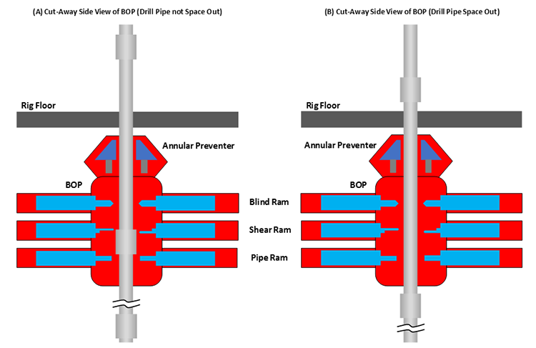
- Pick the drill bit off-bottom and Space Out (Spacing out refers to pulling the drill pipe out the hole so that the top connection – the thickest part of the drill string containing the threads and joints – is several feet above the rig floor. Spacing out ensures that the smaller diameter section of the drill string is inside the BOP, so that pipe rams can close and seat properly or blind rams or shear rams are opposite the smallest diameter section of steel. See Figure 9.15B)
- Stop the mud pumps and check for continued Mud Returns (flow of mud from the well).
- If mud returns continue:
- Shut-in the well with the annular preventer or pipe rams:
- Hard shut-in (choke in Figure 9.12 is closed)
- Soft shut-in (choke in Figure 9.12 is opened)
- If a hard shut-in was used, open the choke
- Weight Up (add the mud weighting additives) to the desired density – this is the Kill Fluid used to Kill the Well
- Circulate the kill fluid through the kill line, down the wellbore, and out of the choke (see Figure 9.12) using an industry standard method:
- The Driller’s Method
- The Weight and Wait Method
- Shut-in the well with the annular preventer or pipe rams:
Other procedures will be used if the kick occurs while tripping into or out of the well. The details of some aspects of this procedure such as hard or soft shut-ins and the circulation methods, The Driller’s Method and The Weight and Wait Method, will be discussed in detail in your later drilling classes. More importantly, for every well that you are involved with, there will always be Daily Safety Meetings that discuss the current status of the well and the important safety aspects of all drilling activities related to that day’s operations.
So, we have discussed the role of drilling fluid to exert pressure on porous and permeable formations and to coat them with an impermeable filter cake to help prevent kicks from occurring. We have also discussed the role of the blowout preventer and company procedures to control a kick once one occurs. So, how do blowouts happen?
Perhaps you remember the Macondo Blowout (Deep Water Horizon Rig) disaster. The name Macondo was the Prospect name (remember, we discussed prospects and well proposals in a previous lesson) while the Deep Water Horizon was the name of the rig. This was the largest oil spill in the Gulf of Mexico. When the disaster occurred, eleven members of the rig crew were killed by the explosion when the natural gas ignited.
The following YouTube video, "Deepwater Horizon Blowout Animation" (11:22), describes the Deep Water Horizon disaster and what its root causes were:
After learning about offshore drilling rigs, drilling crews, components of the drilling rig, kicks, and blowouts, I would highly recommend watching the movie “Deep Water Horizon” and use your knowledge about oil and gas well drilling to identify some of the technical aspects of the film. Ask yourselves some technical questions:
- What type of offshore drilling rig was the Deep Water Horizon?
- What type of well was being drilled (exploration, appraisal/delineation, or development well)?
- What part of the rig crew were the main characters (both the “good guys” and the “bad guys”)?
- What companies (operating companies, drilling companies, or service companies) did these characters work for?
- What were the root causes of the disaster?
- Why were running Cement Bond Logs (CBL) – well logs showing the quality of the cement job –and pressure-testing the cement so important to averting this disaster?
- What is “real” and what is “Hollywood”?
9.3: The Drilling Process
We have discussed the components of the drilling rig, now let’s discuss the drilling process itself. An oil or gas well is drilled in a very ordered sequence. The steps in this sequence are almost universally applied to the drilling of all wells.
- Plan the Well: As we have discussed, exploration well prospects are generated by exploration geologists; while development wells locations and objectives are generated by development geologists. Once the surface locations and well objectives are known, the geologists work with the drilling engineers to develop the detail drilling proposals. In addition, all permits (environmental, safety, regulatory, etc.) are acquired during the final stages of the planning process when a solid well proposal is developed.
- Perform Shallow Gas Survey: To ensure there are no shallow gas hazards which may result in a kick or blow out, a shallow gas survey is performed to identify the locations and depths of any potential shallow gas hazards. Preliminary surface locations and well trajectories may be altered from the original well proposal to avoid these shallow gas hazards.
- Prepare the Wellsite: The site preparation involves building clearing land for use by the rig, building access roads to the well site or well pad, construct infrastructure for water, water disposal, and electricity, dig and line all mud pits to prevent ground water or water table contamination, dig reserve pits for cutting storage (for eventual disposal), and drill the holes which will eventually become the rat hole and the mousehole. The site preparation may involve multiple contractors and companies to perform all of the required work. As we discussed in earlier lessons, a lot of site-preparation time and the environmental footprint can be minimized if multi-well pads are used in the field development.
- Set the Conductor Casing: Prior to the arrival of the drilling rig, an Auger Unit (in hard rock regions) will drill a large diameter hole capable of accommodating 18 in. to 36 in. conductor casing (see Figure 9.16). In soft rock regions or at offshore locations, a diesel hammer may be used to hammer the conductor casing into place. The conduct casing may go to depths of 40 to 300 ft depending on the location. The conductor casing is typically set through the top soil and loose rocks to the bed rock. The objective of the conductor casing is to isolate the wellbore from the top soil to ensure that loose debris does not enter the well during early drilling operations. The conductor casing is then cemented into place.
- Move-In and Rig Up (MIRU): Once the wellsite is prepared and the conductor casing is in-place, the rig is brought on location. Most land rigs, particularly those in North America, are transported on multiple trucks. Once on the well site or well pad, the rigging-up process begins. Rigging up the well consists of taking the rig modules from the trucks and assembling the rig. Included in the rigging up process is setting-up all of the rig systems and testing these systems. Here is a YouTube video, "Rigging up Land Drilling Rig" (3:35), showing the Rigging Up process of the derrick:
Pioneer Drilling 60 Series Rig-up Animation | Drilling Animation | Land Rig Animation | Oil & Gas. This video contains only background music with no words.Source: Industrial3D Inc | I3D [10].
Transporting and assembling the rig may take 50-75 workers (two crews), 35 – 40 vehicles, and take up to four days. If a multi-well pad is used, once the rig is rigged-up for the first well, then the rig can simply be skidded over to the next location without having to dig-down. - Spud the Well: After the rig has been inspected and all of the systems tested the well can be Spudded. Spudding a Well refers to starting the rotary drilling operations for that well.
- Drill Down to the Surface Casing Depth: The first section of the well to be drilled is the section that goes down to the pre-determined surface casing depth (Casing Point). Obviously, for this section of the wellbore, the drill bit diameter must be smaller than the ID (inner diameter) of the conductor casing. In this shallow section of the wellbore, fresh water aquifers (both for personal and municipal use) exist. As discussed earlier, shallow gas hazards may also exit. The objectives of drilling this first section of the well is to allow the setting and cementing of the surface casing to:
- protect the fresh water aquifers by placing a steel and concrete barrier to isolate the water table from the well;
- protect the well from the aquifer (cutting of the drilling fluids with fresh water);
- protect the well from shallow gas hazards.
- Run and Cement the Surface Casing: Once the surface casing point is reached, the surface casing is run into the wellbore and cemented into place. This process is performed by:
- Pulling Out of Hole (POOH): Tripping out of the hole with the drill pipe to remove it from the wellbore during cementing operations;
- running the surface casing;
- pumping a cement slurry down the interior of the casing;
- chasing the cement with drilling fluid to displace the cement up into the annular space between the casing string and the wellbore (rock);
- allowing time for the cement to Cure (harden).
The BOP is then installed on the surface casing string. - Continue this Process to Drill to the Next Casing Point: This drilling process is continued to the next pre-determined casing point. The selection of these intermediate-string casing points is beyond the scope of the class, but the criteria are based on the mud weight, the Fracture Pressure of the formations to be drilled (the pressure that causes the formation to fracture), the locations of any Lost Circulation Zones, and the locations of any High Pressure Zones. As we discussed earlier, any of these situations may result in a kick and a potential blowout. The objectives of the intermediate casing strings are:
- isolate unstable hole sections behind pipe;
- isolate lost circulation zones behind pipe;
- isolate under-pressured zones behind pipe (prevent lost circulation);
- isolate over-pressured zones behind pipe (prevent a kick);
- isolate multiple producing zones
- Continue this Process to Drill to each Casing Point: This process is repeated for each of the planned casing points. Obviously, as successive casing strings are run and cemented into place, smaller diameter tools and drill bits must be used for continued drilling operations. As we discussed earlier, the two most important drilling parameters within the Driller’s control to maximize the Rate of Penetration (ROP) of the drill bit are the weight-on-bit and the rotational speed of the rotary system in Revolutions per Minute (RPM).
- Continue this Process to Drill to Total Depth (TD): Once the final intermediate casing string is run and cemented, the drilling process is continued until the well reaches the TD (Total Depth) of the well. At this point, the well is said to be TD’ed.
- Log the Well with Open-Hole Logs: At this point, the sand face is exposed to the well and Open-Hole Logging Tools can be run in the well. Open-hole logs are used to measure certain properties of the subsurface formation that are of interest to the geologists and engineers working on the well and the reservoir.
- Run and Cement the Production Casing String or Liner: If a production casing string or production liner is to be used in the completion, then they are run and cemented at this time.
- Compete the Well: Install the well completion as discussed in earlier lessons:
- tubing
- gravel packs
- packers
- sliding sleeves
- stimulation
- acidize the well
- hydraulically fracture the well
- artificial lift
- Rig Down and Move Out
Finally, here is a YouTube video, "Drilling Animation" (5:58), showing the entire drilling process. This animation is from Chesapeake Energy, and it discusses the drilling process for a Marcellus Shale well:
9.4: Key Learnings
- There are five major systems on a modern rotary drilling rig:
- the Power System
- the Hoisting System
- the Circulation System
- the Rotary System
- the Well Control System (Blowout Prevention System)
- The power system is the system is the system that provides all power to the rig. On a modern rotary rig, this power is generated with the Prime Mover which is an electrical generator that is fueled with either diesel fuel or lease fuel. The electrical power is transmitted to the other systems and sub-systems on the rig by mechanical means (older rigs), direct current (DC), or alternating current (AC).
- The hoisting system is the system that does the heavy lifting on the rig. It is responsible for lifting drill pipe during tripping operations; and lifting and suspending the drill pipe during drilling operations, and lifting and installing the casing, tubing strings, and completion equipment into the well. In addition, the braking system on the hoisting system controls the weight-on-bit by taking up some of the load of the drill pipe.
- The circulation system of the drilling rig is responsible for circulating the drilling fluid from the mud pit to the drill bit and back. It is a continuous system of pumps, distribution lines, storage tanks, storage pits, and cleansing units that allows the drilling fluid to fulfill its primary objectives (these will be discussed later in this lesson). The main sub-systems of the circulation system are:
- the mud pit
- the mud pump
- the swivel
- the drill string
- the solids control system:
- the shale shaker
- the desander
- the desilter
- the degaser
- The drilling fluid itself is most often called mud. The drilling fluids discussed in these lesson notes are:
- water-based muds (WBM): mixtures of water, bentonite clay, and additives;
- oil-based muds (OBM): mixtures of with diesel oil, mineral oil, or synthetic oils as a continuous phase and water as a dispersed phase in an emulsion. In addition, additives such as emulsifiers and gelling agents are also used;
- foams: comparable to shaving cream; and
- air.
- Drilling fluids are critical in modern drilling operations. There are many objectives for using a drilling fluid. These include:
- lift drill cuttings from the bottom of the wellbore to the surface;
- suspend cuttings to prevent them from falling downhole if circulation is temporarily ceased;
- release the cuttings when they are brought to the surface;
- stabilize the borehole during drilling operations (exert hydrostatic or hydrodynamic pressure on the borehole to prevent rock caving into the wellbore);
- control formation pore pressures to assure desired well control (apply hydrostatic and hydrodynamic pressures in excess of the formation pore pressures to prevent fluids from entering the wellbore);
- deposit an impermeable filter cake onto the wellbore walls to further prevent fluids from permeable formations from entering the wellbore;
- minimize reservoir damage (assure low skin values) when drilling through the reservoir section of the well;
- cool the drill bit during drilling operations;
- lubricate the drill bit during drilling operations;
- allow for pressure signals from Logging While Drilling (LWD) or Measurement While Drilling (MWD) tools to be transmitted to the surface (LWD and MWD data are transmitted to the surface using pressure pulses in the drilling fluid);
- allow for pressure signals to be sent to the bottom of the well to pressure actuate certain downhole equipment;
- minimize environmental impact on subsurface natural aquifers.
- The rotary system of the drilling rig provides the torque for the drilling process. This torque is provided by the rotary table on a conventional rotatory rig or the top-drive unit on a top-drive rotary rig. This torque is conveyed through the drill pipe and the bottom-hole assembly to the drill bit.
- The lesson notes discussed three types of drill bits used on the drilling industry:
- milled-tooth tri-cone bit
- insert tri-cone bit
- fixed-cutter bit
- The drilling action of the tri-cone bits is due to an explosive gouging, crushing action; while the drilling action of the fixed-cutter bits are due to a scraping action.
- In a milled-tooth tri-cone bit, the teeth of the bit are milled from the same steel as the cone. Due to the grade of the steel used in the cones, the milled-tooth bits are typically used to drill through soft rock formations.
- In an insert tri-cone bit, the teeth inserts are made from stronger grades of steel than the cone. Typically, tungsten-carbide steel is used to create the teeth in an insert bit. The insert bits are used to drill through moderately hard formations or to extend the bit-life through soft formations.
- Fixed-cutter bits are bits that contain no moving parts. The cutters on fixed-cutter bits are typically polycrystalline (synthetic) diamonds which are used to form polycrystalline diamonds compact (PDC) bits. PDC bits are used to drill through hard rock formations.
- The Well Control System or the Blowout Prevention System is the system on a drilling rig that prevents the uncontrolled, catastrophic release of high-pressure fluids (oil, gas, or salt water) from subsurface formations. The well control system is comprised of:
- the Accumulator: stores compressed gas and compressed hydraulic fluids for the rig’s hydraulic systems;
- the Blowout Preventer: large stacked system of high-pressure valves that can be closed around or through drill pipe to isolate the subsurface formations from the rig.
- The well control system provides well control by:
- mud system: helps prevent kicks by exerting high hydrostatic and hydrodynamic pressures on the formations and depositing an impermeable mud cake across permeable formations;
- blowout preventer (BOP): helps to control a kick if one occurs.
- A kick is an unwanted but controllable entry of subsurface fluids into the wellbore; while a blowout is a catastrophic (usually) and uncontrollable entry of subsurface fluids into the wellbore. Blowouts can be catastrophic because of the combustible nature of hydrocarbons.
- The causes of a kick include:
- insufficient mud weight (density): the hydrostatic or hydrodynamic pressure exerted by the mud column is less than the formation pore pressure (the pressure is underbalanced);
- improper mud replacement during tripping: while tripping out of the hole mud volumes must be pumped into the wellbore at high enough rates to replace drill pipe being removed from the wellbore;
- swabbing: removing drill pipe from the wellbore can create a negative pressure (suction) if the drill pipe is removed too quickly;
- cut mud: if gas is entering the wellbore, then it may effectively reduce the wellbore pressure gradient;
- lost circulation: as discussed earlier if large volumes of drilling fluid enter the subsurface in (1) high permeability formations, natural fractures, or drilling-induced fractures, then the effect is a shortened height and weight of the mud column.
- The indicators/warning signs of a kick include:
- increase in the rate of flow of the drilling fluid returns at constant pump rates (primary indicator of a kick);
- volume of mud in the mud pit increases when no additional drilling fluids are added to the mud system (primary indicator of a kick);
- drilling fluids returns continue to flow when the mud pumps are turned off (primary indicator of a kick);
- improper wellbore fill-up/volume-balance on trips (primary indicator of a kick);
- pump pressure decrease and pump stroke increase (secondary indicator of a kick);
- change in the apparent weight-on-bit (secondary indicator of a kick);
- occurrence of a Drill Break or Bit Drop (secondary indicator of a kick);
- reduction in the mud weight (secondary indicator of a kick).
- The drilling company and operating company will always have a detailed, well-specific procedure in place in the advent of a kick.
- All wells are drilled with a set sequence of operations.
9.5: Summary and Final Tasks
Summary
We began this lesson by discussing the five major systems on a modern rotary drilling rig. These are:
- the Power System
- the Hoisting System
- the Circulation System
- the Rotary System
- the Well Control System (Blowout Prevention System)
We discussed each of these systems along with the more important sub-systems that comprise these systems.
The power system on a drilling rig provides the for the other main systems on the rig and other ancillary systems, such as electrical systems, pumps, etc. The system typically consists of a prime mover (the component of the power system that generates the raw power) and a means to transmit the raw power to the end-use components on the rig. The sub-systems of the power system that were discussed in detail or listed and shown in Figure 9.02 include:
- the Fuel Storage
- the Engines and Generators
- means of power transmission
- mechanical
- direct current
- alternating current
The hoisting system on a drilling rig does the heavy lifting on the rig. It is used to raise, lower, and suspend the drill string and lift casing and tubing for installation into the well. The sub-systems of the hoisting system that were discussed in detail or listed and shown in Figure 9.02 include:
- the Crown Block
- the Mast/Derrick
- the Monkey Board
- the Traveling Block
- the Hook
- the Swivel
- the Drawworks
- the Weight Indicator
- the Drilling Line
The circulation system on a drilling rig allows for circulation of the Drilling Fluid or Mud down through the hollow drill string and up through the annular space between the drill string and wellbore. It is a continuous system of pumps, distribution lines, storage tanks, storage pits, and cleansing units that allows the drilling fluid to fulfill its primary objectives. The sub-systems of the circulation system that were discussed in detail or listed and shown in Figure 9.02 include:
- the Swivel
- the Rotary Hose
- the Mud Return Line
- the Shale Shaker
- the Choke Manifold
- the Mud Gas Separator
- the Degasser
- the Reserve Pit
- the Mud Pits
- the Desander
- the Desilter
- the Mud Pumps
- the Mud Discharge Line
- the Bulk Mud Components Storage
- the Mud House
- the Water Tank
The drilling fluid (mud) is a critical part of the drilling process. Muds can be water-based fluids, oil-based fluids, foam, or air. The objectives/functions of the mud are:
- lift drill cuttings from the bottom of the wellbore to the surface;
- suspend cuttings to prevent them from falling downhole if circulation is temporarily ceased;
- release the cuttings when they are brought to the surface;
- stabilize the borehole during drilling operations (exert hydrostatic or hydrodynamic pressure on the borehole to prevent rock caving into the wellbore);
- control formation pore pressures to assure desired well control (apply hydrostatic and hydrodynamic pressures in excess of the formation pore pressures to prevent fluids from entering the wellbore);
- deposit an impermeable filter cake onto the wellbore walls to further prevent fluids from permeable formations from entering the wellbore;
- minimize reservoir damage (assure low skin values) when drilling through the reservoir section of the well;
- cool the drill bit during drilling operations;
- lubricate the drill bit during drilling operations;
- allow for pressure signals from Logging While Drilling (LWD) or Measurement While Drilling (MWD) tools to be transmitted to the surface (LWD and MWD data are transmitted to the surface using pressure pulses in the drilling fluid);
- allow for pressure signals to be sent to the bottom of the well to pressure actuate certain downhole equipment;
- minimize environmental impact on subsurface natural aquifers.
The rotary system on a drilling rig is the system that causes the drill bit rotate at the bottom of wellbore. We have discussed some components of the rotary system when we discussed rotary table and top-drive rigs, but we have not yet discussed the entire system. The sub-systems of the rotary system that were discussed in detail or listed and shown in Figure 9.02 include:
- the Swivel
- the Kelly or (Top-Drive Unit on a top-drive rig)
- the Kelly Bushing or (Top-Drive Unit on a top-drive rig)
- the Master Bushing or (Top-Drive Unit on a top-drive rig)
- the Rotary Table or (Top-Drive Unit on a top-drive rig)
- the Mousehole
- the Rat Hole
- the Rotary Hose
- the Drill String
- the Bottom-Hole Assembly
- the Drill Bit
Drill bits come in different shapes and sizes. The choice of the appropriate bit depends on the formations to be drilled. The drill bits that we discussed in this lesson include:
- milled-tooth tri-cone bit (for drilling through soft rock formations)
- insert tri-cone bit (for drilling through medium to hard rock formations)
- fixed-cutter bit (for drilling through hard rock formations)
The well control system or the blowout prevention system on a drilling rig prevents the uncontrolled, catastrophic release of high-pressure fluids (oil, gas, or salt water) from subsurface formations. The sub-systems of the well control system that were discussed in detail or listed and shown in Figure 9.02 include:
- the Accumulator
- the Blowout Preventer
A kick is an unwanted but controllable entry of subsurface fluids into the wellbore; while a blowout is a catastrophic (usually) and uncontrollable entry of subsurface fluids into the wellbore. Blowouts can be catastrophic because of the volatile, combustible nature of hydrocarbons.
The causes of a kick include:
- insufficient mud weight (density): the hydrostatic or hydrodynamic pressure exerted by the mud column is less than the formation pore pressure (the pressure is underbalanced);
- improper mud replacement during tripping: while tripping out of the hole mud volumes must be pumped into the wellbore at high enough rates to replace drill pipe being removed from the wellbore;
- swabbing: removing drill pipe from the wellbore can create a negative pressure (suction) if the drill pipe is removed too quickly;
- cut mud: if gas is entering the wellbore, then it may effectively reduce the wellbore pressure gradient;
- lost circulation: as discussed earlier, if large volumes of drilling fluid enter the subsurface in (1) high permeability formations, natural fractures, or drilling-induced fractures, then the effect is a shortened height and weight of the mud column.
The indicators/warning signs of a kick include:
- increase in the rate of flow of the drilling fluid returns at constant pump rates (primary indicator of a kick);
- volume of mud in the mud pit increases when no additional drilling fluids are added to the mud system (primary indicator of a kick);
- drilling fluids returns continue to flow when the mud pumps are turned off (primary indicator of a kick);
- improper wellbore fill-up/volume-balance on trips (primary indicator of a kick);
- pump pressure decrease and pump stroke increase (secondary indicator of a kick);
- change in the apparent weight-on-bit (secondary indicator of a kick);
- occurrence of a Drill Break or Bit Drop (secondary indicator of a kick);
- reduction in the mud weight (secondary indicator of a kick).
Safety is of the utmost importance in the oil and gas industry, and detailed well procedures are developed for each well. In addition, daily safety meetings discussing the status of the well, the day’s operations, and the safety concerns for that day’s operations are typically performed by all responsible drilling companies and operating companies.
Finally, we discussed the steps in the drilling procedure (Making Hole). An oil or gas well is drilled in a very ordered sequence. The steps in this sequence are almost universally applied to the drilling of all wells. These include:
- plan the Well
- perform Shallow Gas Survey
- prepare the Wellsite
- Set the Conductor Casing
- Move-In and Rig Up
- Spud the Well
- Drill Down to the Surface Casing Depth
- Run and Cement the Surface Casing
- Continue this Process to Drill to the Next Casing Point
- Continue this Process to Drill to each Casing Point
- Continue this Process to Drill to Total Depth (TD)
- Log the Well with Open-Hole Logs
- Run and Cement the Production Casing String or Liner (if part of the completion design)
- Compete the Well – install the well completion:
- Tubing
- Gravel packs
- Packers
- Sliding sleeves
- Stimulation
- Acidize the well
- Hydraulically fracture the well
- Artificial lift
- Rig Down and Move Out
Final Tasks
Complete all of the Lesson 9 tasks!
You have reached the end of Lesson 9! Double-check the to-do list on the Lesson 9 Overview page [11] to make sure you have completed all of the activities listed there before you begin the Final Exam Review week.