The principle of Corresponding States (PCS) was stated by van der Waals and reads: “Substances behave alike at the same reduced states. Substances at same reduced states are at corresponding states.” That is,
“Substances at corresponding states behave alike.”
Reduced properties are used to define corresponding states. Reduced properties provide a measure of the “departure” of the conditions of the substance from its own critical conditions and are defined as follows:
(8.1a)
(8.1b)
(8.1c)
If Pr = Tr = vr = 1, the substance is at its critical condition. If we are beyond critical conditions, Tr > 1, Pr > 1 and vr > 1. By the same token, if all the conditions are subcritical, Tr < 1, Pr < 1 and vr < 1. Critical conditions become the scaling factor by which substances can be compared among each other in terms of their “departure from criticality” or reduced properties.
The PCS says that all gases behave alike at the same reduced conditions. That is, if two gases have the same “relative departure” from criticality (i.e., they are at the same reduced conditions), the corresponding state principle demands that they behave alike. In this case, the two conditions “correspond” to one another, and we are to expect those gases to have the same properties.
The Corresponding State Principle can be derived from vdW EOS. If we recall,
(8.2a)
where:
(8.2b)
(8.2c)
We defined the reduced conditions as:
(8.3)
If we substitute all this into vdW EOS,
(8.4)
Simplifying the expression, and employing the expressions:
(8.5a)
(8.5b)
We get:
(8.6)
Equation (8.6) is the reduced form of vdW EOS. See how this equation is “universal”. It does not care about which fluids we are talking about. Just give it the reduced conditions “Pr, Tr” and it will give you back vr — regardless of the fluid. Hence, if you compute vr for a certain fluid by entering Pr and Tr for that fluid into vdW reduced EOS (equation 8.6), you will compute the same vr, for any other fluid at the same conditions of Pr and Tr. There is no other possibility. Strictly speaking, van der Waals’ Corresponding States Principle reads: “fluids at the same reduced pressures and temperatures have the same reduced volume.” This is how van der Waals discovered the Principle of Corresponding States. As long as two gases are at corresponding states (same reduced conditions), it does not matter what components you are talking about, or what is the nature of the substances you are talking about; they will behave alike.
The critical point provides the perfect scaling for the application of the corresponding state principle because of the existence of the criticality conditions. In fact, equation (7.13) [Module 7] makes the application of corresponding states possible for equations of state.
(7.13)
Indeed, for us to arrive at equation (8.6), we needed to use equations (8.2) — which in turn were the outcome of the application of the criticality conditions to van der Waals’ equation of state. As a result, gases that have the same relative departure from their own critical condition have the same properties.
What is the use of this principle? Basically, it is used for thermodynamic correlations — its most powerful application. Most thermodynamic correlations have been made viable and general because of the application of the principle of corresponding states. An excellent example is the popular Z-chart of Standing and Katz, shown in Figure 8.1. In fact, most of the correlations that we use in thermodynamics are based on this principle. This explains why “Pr” and “Tr” so often appear in thermodynamic correlations. The main reason for using “Pr” and “Tr” is to obtain the most generalized correlation possible, so that it is suitable for use with most substances.
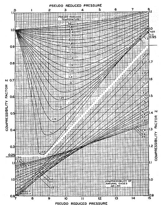
(Reference: Standing and Katz, Trans. AIME, 1942)