Station diagrams, observation logs, and to-reach descriptions that would rarely be necessary in real-time GPS/GNSS surveying. However, some components of static GPS/GNSS control methods are useful. One such technique is offsetting points to avoid multipath and signal attenuation.
Point Offsets
The need to offset points is prevalent in real-time GPS/GNSS. For example, an offset point must often be established far enough from the original position to avoid an obstructed signal, but close enough to prevent unacceptable positioning error. While the calculation of the allowable vertical and horizontal measurement errors can be done trigonometrically, the measurements themselves will be different than those for an offset point in a static survey. DGPS/GNSS and RTK surveying generally have lower accuracy requirements than does static control, and therefore, the establishment of the tie between an offset and the originally desired position need not be so stringent. For example, rather than the total station point and an azimuth point used in static work, a magnetic fluxgate digital compass and laser may be used to measure the tie from the offset point to the original point might be used in real-time work. It is worth noting that magnetic declination must be accommodated, and metal objects avoided when using a magnetically determined direction. Such internal compasses should be carefully checked before they are relied upon. The length of the tie may be measured by an external laser, a laser cabled directly into the GPS/GNSS receiver, or even a tape and clinometer. Lasers are much more convenient since they can be used to measure longer distances more reliably, and taping requires extra field crew members. Rather than recording the bearing and distance in a field book for postprocessing, the tie is usually stored directly in the data collector. In fact, often the receiver’s real-time processor can combine the measured distance and the direction of the sideshot with the receiver’s position and calculate the coordinate of the originally desired position.
Dynamic Lines
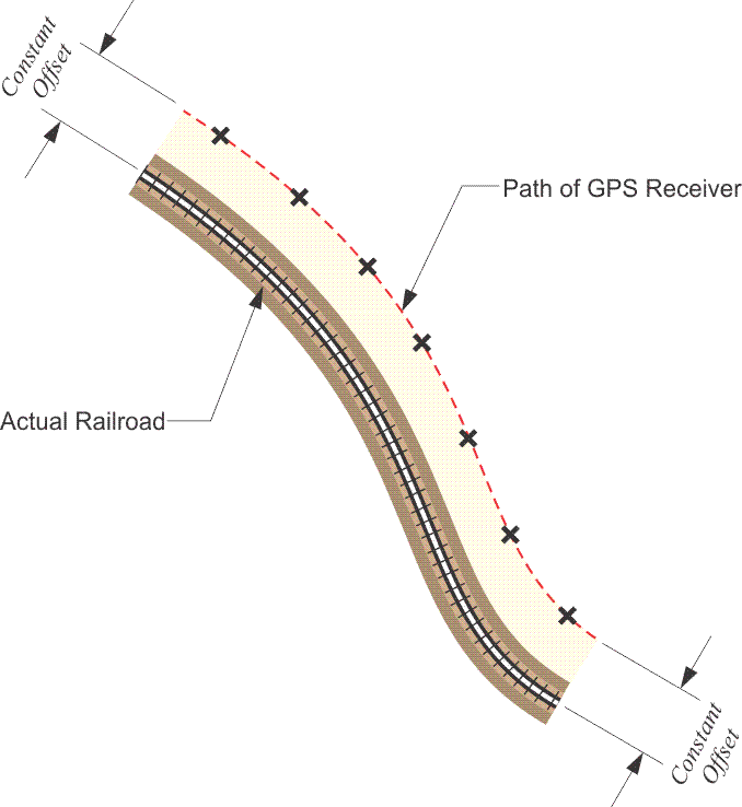
A technique unique to RTK and DGPS/GNSS and used especially in mobile GPS/GNSS application is the creation of dynamic lines. The GPS/GNSS receiver typically moves along a route to be mapped, logging positions at pre-determined intervals of time or distance. These points can then be joined together to create a continuous line. Obstructions along the route present a clear difficulty for this procedure. Points may be in error, or lost completely, due to multipath or signal attenuation. Also, in choosing the epoch interval, the capacity of the receiver’s memory must be considered, especially when long lines are collected. If the interval chosen is too short, the receiver’s storage capacity may be overwhelmed. If the interval is too long, important deflections along the way may be missed. Where it is impossible or unsafe to travel along the line to be collected in the field, the dynamic line may be collected with a consistent offset. This technique is especially useful in the collection of roads and railroads, where it is possible to estimate the offset with some certainty due to the constant width of the feature. It is also possible, of course, to collect routes with individual discrete points with short occupations where that approach recommends itself.