Module 6: Explosives and Blasting
Module 6 Overview
Module 6 Overview
We looked at unit operations in the last module, and learned that in a conventional cycle we have a drill-blast-load-haul sequence of operations; but we did not discuss the unit operation of blasting. We’ll do that in this module.
We use millions of pounds of explosives every week in mining to loosen overburden so that it is easier to dig, to break rock so that it can be freed from the rock face and loaded, and to create openings in underground mines, among dozens of other uses. Moreover, we do this with no injuries or fatalities and a minimum number of complaints from the mines’ neighbors. It is not an accident that we have achieved these positive outcomes; rather, it is good engineering.
In this module we’ll learn: about the blasting agents commonly used in the mining industry; how to design a blast round; how to initiate a blast; and how to avoid poor blasting outcomes.
Learning Outcomes
At the successful completion of this module, you should be able to:
- demonstrate knowledge of the basic properties of explosives, including oxygen balance, the basic concepts of fragmentation, the blasting agents, and the initiation technologies commonly used in mining;
- demonstrate knowledge of the design parameters for a blast:
- burden, spacing, and free face,
- hole diameter, length, stemming, decking,
- powder factor,
- fragmentation and throw,
- ground vibration and air blast;
- demonstrate knowledge of typical blasting practices for:
- bench blasting rounds for surface and underground mines,
- stoping or drifting rounds;
- calculate:
- powder factor for a given blast round,
- burden, spacing, and stemming distance given a blast hole diameter or given a typical powder factor,
- maximum charge weight/delay, given a vibration limit;
- demonstrate a knowledge of the factors that can adversely affect the outcome of a blast, or the relationship of poor engineering, drilling or explosives blending/loading practices on the outcome of the blast;
- identify potential safety and health issues, and proactive measures to prevent adverse outcomes, related to the following:
- storage and handling,
- flyrock,
- fume and dust exposure,
- air blast and vibration.
Lesson 6.1: The Big Bang
Lesson 6.1: The Big Bang
The mining industry is a major consumer of explosives, and the ore winning process is heavily dependent on blasting. The purchase and use of explosives is a significant cost, but a potentially greater cost is the effect of the blast on the overall cost of the product. An improperly designed or executed blast can increase loading time and cost, create future ground control problems, i.e., delays and costs, increase crushing costs, cause excessive fines that may be unsalable, and so on. Paying close attention to the results of each blast, and taking appropriate corrective action, can yield immediate benefits. Of course, you have to know what to look for, and how to achieve a desired result. So, let’s start at the beginning, and answer two fundamental questions! Why do we blast, and how do we blast?
6.1.1: Why do We Blast?
6.1.1: Why do We Blast?
Yes, we blast to break the rock, but we have specific goals beyond simply achieving fragmentation of the rock! The desired outcome of a blast is broken material:
- fragmented to a specified size distribution,
- thrown a certain distance, and
- distributed in a pile that is placed to facilitate loading.
The size distribution is important for several reasons, and these reasons vary with different commodities.
Generally, the blasted material must be handled in some fashion, e.g., to load it into a haul truck or to cast it onto a spoil pile. The size of the blasted material must be consistent with the capabilities of the equipment that will be used to move it.
Oversize rock, i.e., rock that is larger than can be handled, can’t be loaded or if it can be loaded, it is too large to fit into the crusher. This creates multiple problems. It introduces delays in production, it is time-consuming, costly, and sometimes dangerous to practice what is known as secondary breakage.
The production of fines, i.e., very small particles, in the blast can be desirable in certain cases where an ore is to be beneficiated. In other cases, excess production of fines is undesirable. In the crushed stone market, for example, fines are excluded from many products, and it is expensive to re-handle and dispose of an unsaleable product.
The throw distance and the pile placement are closely related.
Pile placement
Pile placement is the distribution of the blasted material. Is the pile of blasted rock 30’ wide, 10’ long, and 10’ deep, or is 30’ wide, 80’ long, and 15” deep, or somewhere in between? There will be an optimum depth for loading. If the pile is too deep, the loader will waste time digging to load the bucket. If the pile is too dispersed, time will be wasted maneuvering over a large area to load the material.
Throw distance
This is how far the blasted material is moved. There are examples in surface mining where the blast is used to move material to a previously mined strip, rather than using a dragline or shovel. This is known as cast blasting, and obviously the distance that the blasted material is moved is a critical performance parameter. Throw is also important to ensure that the blasted material can be loaded or dug. Without adequate throw, the fragmented material will sit back down, and be extremely difficult to access. This can be a problem when advancing a face in an underground mine and, accordingly, we design the blasting pattern to ensure that the fragmented rock is lifted and thrown away from the virgin rock.
6.1.2: How do We Blast?
6.1.2: How do We Blast?
Very carefully! Actually, I am serious!!! There’s a difference between civil and military blasting. In the latter, their goal is usually to “blow things up.” In civil projects, such as mining, our goals are to use as little explosive as possible, as safely as possible, and to have no collateral damage, while achieving the design outcome for the blast. This is not easily accomplished and requires both good engineering and faithful implementation of the blast design by the drillers and blasters. The short answer to the question of “how do we blast” is as follows.
- We create a cavity, typically a drilled hole, to accept an explosive. The diameter of the hole will depend on the amount of explosive energy that we want in the hole.
- We will drill multiple holes, and the distances among the holes will be an engineered parameter.
- We fill the cavity, partially, with a blasting agent, i.e., an explosive. The type and formulation of explosives is an engineering decision.
- We place initiators, primers, and sometimes boosters in the hole with the blasting agent.
- The initiators trigger the process. They can be nonelectric or electric, and some are commonly known as blasting caps. These initiators may include a time delay, which allows us to design a specific sequence for the initiation of the blast.
- The primer is a small explosive charge that is set off by the initiator, and which has sufficient energy to set off the blasting agent. Explosives commonly used today are not cap-sensitive, meaning that the initiators do not have enough energy to set off the blasting agent. For this reason, we need to insert the initiator into the primer before dropping it into the hole.
- Boosters are used to ensure that the explosion propagates through the entire column of explosive. This is a concern in longer holes and holes of smaller diameter.
- We connect the initiators in each hole together using nonelectric tube/cord or electric wires, and these terminate at the point where the blast will be fired, i.e., the blaster will “push the plunger” or “throw the switch.”
The placement of the holes and the timing sequence of when the holes are “fired” constitute the blasting pattern.
Collateral Damage
I said that one of the goals of blasting is to avoid collateral damage, which we do through proper design and execution of the blast. But, what do we mean by collateral damage? Here are the primary ones that we constantly have to assess.
Overbreak
This is when fractures from the blast propagate beyond the intended region. Imagine that you want to drill and blast a tunnel opening through a mountain, and you are designing for an opening that is 30’ wide and 15’ high. However, due to improper design or execution, cracks have propagated to 18’ high. Over time, it is likely that pieces of rock will begin to fall out of the tunnel roof, creating a safety hazard as well as delays in using the tunnel.
Flyrock
Flyrock is a large chunk of rock that is propelled well beyond the throw region for the blast. These chunks can weigh hundreds of pounds or even more than a ton, and travel distances of several hundred feet. Over the years, flyrock has caused numerous fatalities and millions of dollars of property and equipment damage. Proper design and execution are necessary to prevent flyrock.
Gas production
Gas production is an intended action during a blast, but the production of excess quantities of toxic gases, notably CO and NOx, is to be avoided. Improper on-site formulation of the blasting agent and problems with loading are often responsible for this problem. It should be noted that this is a hazard in both surface and underground mines.
Ground vibration
Like gas production, ground vibration is an intended consequence of blasting. However, excessive ground vibration can damage structures, and the level of vibration at the boundary of the mine’s property is regulated. Careful design of the blasting pattern, and especially the timing of the holes, is required to keep the ground vibration within prescribed limits.
Air blast
This occurs when excess energy from the blast creates a shock wave in the air. Certain weather conditions will cause the air blast to be bounced back to the surface but at some distance from the blast. There is little danger of personal or structural damage from an air blast, but it can precipitate a barrage of angry complaints from people who live in proximity to a surface mine. Nothing good ever comes from irritating the locals! Air blast can be reduced through proper design the blasting pattern and the choice of detonators used to link the holes together.
Misfires
These are not really “collateral damage” per se, but they are an unintended consequence. A misfire occurs when some of the blasting agent in a hole, or multiple holes, remain undetonated after the blast. This explosive could go off at a later time, such as during loading, and cause serious personal injury or death. Misfires can be avoided through careful attention to the execution, as well as the design, of the blast.
Good Engineering and Execution
Throughout this discussion, I have emphasized the proper design and execution of the blast. By execution, I mean the drilling and loading of the holes. Poor drilling or loading procedures will compromise the best design, and similarly, proper drilling and loading cannot compensate for a poorly engineered blast round.
It starts with good engineering, and specifically:
Design of the blasting round is concerned with:
- the choice of the blasting agent;
- the choice of detonators, primers, and boosters;
- the use of free faces. A free face is an unconfined surface, through which the blasted material is free to move unimpeded;
- the distance between holes, known as the spacing, and the distance between a hole the nearest free face, known as the burden;
- the number of holes;
- the diameter of the hole;
- the depth or length of the hole;
- the use of decking, when needed, and stemming. Decking is an inert material used at certain locations within the column of explosive when it would be undesirable to have explosive at that part of the drill hole. Stemming is an inert material placed in the top or front of the hole. It is necessary to help provide proper confinement for the blast, ensure safety, and reduce airblast;
- the timing of when each hole is detonated;
- the overall positioning or arrangement of the holes, including the use of unloaded holes;
and ends with good execution by the drillers and the blasters. Specifically for the driller:
- accurate positioning of the collar, i.e., drilling the hole exactly at the specified location;
- control the drilling angle, i.e., drilling the hole at exactly the specified angle;
- control the depth or length of the hole;
- accurate logging of the holes during drilling (applicable primarily to surface mining applications);
specifically for the blaster:
- correct mixing of the blasting agent at the hole (if batch loaded);
- proper loading procedures if there is water in the hole;
- correct loading rate;
- correct placement of decking, boosters, and primers;
- proper placement of stemming and stemming to the design depth.
6.1.3: Dance of the Detonators
6.1.3: Dance of the Detonators
I want to conclude this introduction to explosives and blasting with a short video clip (4:04) showing multiple controlled explosions. There is no narration for the video, but the blasts are accompanied with a musical soundtrack.
Look for the following:
- The relative timing of the holes, as indicated by when they detonate.
- The initiation of the blast in the holes prior to the detonation of the explosive, as indicated by the flashes of light moving from hole-to-hole, as well as the small dust clouds at the collar of each hole.
- The movement of the blasted material at the free faces (not always apparent).
- The couple of blasts that are done underwater.
Direct link to video [1] if not showing below
I hope that you enjoyed this video. It is entertaining! It also represents good blasting practice, which you will come to better understand as you learn more about explosives and blasting practice.
Lesson 6.2: Explosives
Lesson 6.2: Explosives
We took a “bird's-eye view” of explosives and blasting in the last lesson. Now, we need to zoom in and look at many of these concepts in greater detail and with more rigor. First, a definition:
An explosive is an agent, compound, or mixture that undergoes very rapid decomposition when initiated by heat, impact, friction, or shock.
- This decomposition is a high-velocity, exothermic reaction, accompanied by the liberation of vast amounts of energy and hot gases at tremendously high pressure.
- High explosives produce shock, which fragments rock, and force, in the form of expanding gases, which displace and throw the rock.
The detonation velocity (DV) is the speed at which the detonation front propagates through a column of explosive.
- The explosive is said to detonate if the DV is supersonic, DV>3000fpm
- The explosive is said to deflagrate if the DV is subsonic, DV<3000fpm
In everyday conversation, some use the word detonate to mean either detonation or deflagration. From this point forward, we should be more precise in our use of the words.
The Three Common Components of Industrial Explosives:
Oxidizers
This group contributes oxygen, and includes nitrated salts such as ammonium, calcium, and sodium nitrate.
Fuels
Fuels produce heat, and include fuel oil, carbon, granular aluminum, TNT, black powder, and other carbonaceous material. Some of these materials are referred to as sensitizers, which increase the energy output, e.g., granular aluminum. We are not going to talk about the use of black powder because it is illegal for use in underground coal mines, and that was its only application to mining. TNT or dynamite is rarely used in mining applications due to the challenges of using it safely. Virtually all explosives used in the mining industry are based on ammonium nitrate and fuel oil (ANFO), and we will confine our discussion to those ANFO-based formulations.

_explosive.jpg)
Stabilizers
These impart properties to improve the handling of the explosive and include flame retardants, gelatins, densifiers, emulsifying agents, and thickeners.
6.2.1: Mixing ANFO and the Oxygen Balance
6.2.1: Mixing ANFO and the Oxygen Balance
The proportion of oxidizers and fuels in the mix is critical to the performance of the explosive, and we say that the explosive must be oxygen balanced.
Oxygen Balance
It is important to achieve an oxygen balance within the explosive. This means there is exactly enough oxygen present to completely oxidize the contained fuel, but none left over to react with the contained nitrogen. We can calculate the proportion of ammonium nitrate and fuel oil to achieve an oxygen-balanced reaction. The decomposition of an oxygen-balanced ANFO is:
We can find the atomic weights for each of the elements from the periodic table.:
N = 14.006
H = 1.0078
N = 14.006
C = 12.009
And then, we can calculate the molecular weight of the ammonium nitrate and the fuel oil.
: molecular weight = 80.05 g/mol
: molecular weight = 14.03 g/mol
The ideal mixture, i.e., the oxygen-balanced mixture, consists of 3 moles of ammonium nitrate and one mole of fuel oil.
Next, we should find the weight ratio of ammonium nitrate to fuel oil.
For 3 moles of : 3*80.05 = 240.15 g
For 1 mole of : 1*14.03 = 14.03 g
The molecular weight of ANFO is, therefore: 240.15 + 14.03 = 254.18 g
The percent by weight is:
: (240.15 / 254.18) *100 = 94.5% by weight
: (14.03 / 254.18) * 100 = 5.5% by weight
So, now we know that when we mix the ammonium nitrate with the fuel oil, we need to do it in this proportion if we want an oxygen balanced reaction.
We can calculate the density of ANFO mixed to this ratio. Why we would we want to do that? If we know the weight per unit volume of the correct mix, then we can tell the blasters who make the mixture in the field to weigh one cup of the mixture to ensure the weight matches the specification weight. Note, I used “cup” as the volume measurement where one cup equals eight fluid ounces. You can use any unit, as long as you are consistent.
Let’s look at an example.
We will assume that the industrial-grade ammonium nitrate and fuel oil have the following densities: 53 lb/ft3 for the ammonium nitrate and 8.0 lb/gal for the fuel oil. How much ammonium nitrate will be required for each gallon of fuel oil to make an oxygen-balanced batch of ANFO? We will need to mix 2.6 ft3 of ammonium nitrate with that gallon of fuel oil. You should verify this result.
Continuing with this example: we know that the blasters will have a scale on the mixing truck and they will have a “cup”, which they will use to do a “cup density” check. In other words, they will fill the cup with their batch of mixed ANFO and weigh it. They will compare that weight to the weight that they have been given as the specified weight. If the blaster is using an 8-ounce container for the cup density check, what weight should be displayed on the scale?
You don’t have sufficient information to answer this question. What is the calculation that you need to do to answer the question, and what are you missing?
Although you know the weight of each ingredient in the mix, you don’t know the density of the mix. The manufacturer of the ammonium nitrate would be able to give you that information, or you could do a simple experiment in the lab to determine the density of that mix. For our purposes here, let’s assume that the density of this mix is 6.68 lb/gal. Therefore, the number that you need to give to your blaster is 0.42 lb.
The mixing equipment on the truck requires regular calibration, and even if calibrated, sometimes it can malfunction. Thus, it is recommended that blasters perform a cup-density check frequently, e.g., every 5 or so holes in a surface mine application.
We’ve looked at the ideal, i.e., oxygen-balanced mixture. Let’s look at two other cases in which we have too little or too much ammonium nitrate for the amount of fuel oil that has been added. We’ll choose a 92: 8 ratio for the first case and a 96.6: 3.4 ratio for the second case I’ve picked these ratios so that we have an integer number of moles in our formula.
Thus, for the first case with a 92:8 ratio, we have:
And for the second case, with a 96.6 : 3.4 ratio, we have:
Let’s look at the right-hand side of the equations. In the case of ideal mix, the products of the reaction, in addition to the energy that is not shown, are water vapor, carbon dioxide and nitrogen. In the first case of too little oxidizer, i.e., the ammonium nitrate, we produce carbon monoxide, a deadly gas. In the second case of too much oxidizer, we produce NO. The gas, NO, changes to NO2 when exposed to the atmosphere. NO2 is a toxic, but unlike CO, which is colorless, NO2 produces a bright yellow-orange cloud.
We are not going to calculate the volume of toxic gas produced, but be aware that it is significant. In addition to the production of toxic gas, the energy release is reduced.
The oxygen balance can be lost for varied reasons. The most common include:
- poor quality control at the batch mixing truck;
- incorrect formulation, for example by adding a sensitizer like aluminum, but not accounting for it in the addition of the fuel oil;
- water in the hole;
- lack of confinement;
- improper stemming;
- improper timing of adjacent holes, allowing the explosive to become unconfined by the time it detonates;
- open-air blasting;
- explosives at the collar of the hole (increases fume production, not fragmentation).
6.2.2: Fumes
6.2.2: Fumes
The whole point of ensuring an oxygen balance is to achieve the maximum energy from the reaction and to prevent the generation of toxic gases. Remember, however, that the production of large quantities of gas is key to the efficacy of the explosive to fragment rock. On average 700 - 1000 l of gases/kg of explosive are produced, and these are mostly benign – N, CO2, and water. It is impractical to achieve a perfect mix in the field, shot after shot, and consequently, a small (<4%) toxic component of about 3% CO and 1% NO2, depending on the oxygen balance, is not unusual. The percentage of toxic gases will increase significantly as the oxygen balance deteriorates.
Due to the possibility of a toxic component in a well-designed blast, certain precautions must be taken. The ventilation system in underground mines must be designed to dilute and carry away the gases from the blast, and no one should be allowed back into that part of the mine until sufficient time has passed to eliminate any gases from the blast. Some mines, and particularly smaller ones, make it a practice of blasting after the crew from the last shift of the day has exited the mine and the next shift won’t return until the following day. Other mines don’t have that luxury, and must ensure that a properly designed ventilation system is in place.
Fumes are normally less of a concern in a surface mine. However, it is important to note that fumes can be trapped in a pile of blasted rock only to be liberated when the pile is loaded out. There have been a few fatalities from this, so this possibility is not to be ignored. The precaution of watering down the pile prior to loading is practiced both underground and in some surface applications. In addition to addressing a potential fume issue, the wetting action suppresses respirable dust.
A significant hazard can develop at surface mines if there is an excess production of NO2 or CO. In the late 1990s, I was part of a team investigating a problem in the Powder River Basin, in which the large blasts were producing thick yellow clouds of NOx – clouds that covered acres, and would drift for miles before dispersing! Fortunately, there were no reported ill effects and no fatalities, and that was lucky. My agency became involved when such clouds from a mine settled in a nearby town, near an elementary school filled with children. In the Basin, the problem was found to be water in the hole primarily, and loss of confinement as a secondary cause.
There was another illustrative problem that we investigated involving CO. These were trench-blasting applications, and there were a few fatalities due to CO poisoning. CO from the blast was trapped in the ground, but over a day or so, the gas migrated along a pipeline and entered a structure (basement), creating a toxic environment in the basement.
Fumes are an expected consequence when explosives are used. Proper procedures can help ensure an oxygen-balanced explosion, but will not guarantee a blast completely free of toxic fumes. Precautions, such as those mentioned here, must be implemented.
6.2.3: Classification of Common Industrial Explosives
6.2.3: Classification of Common Industrial Explosives
The U.S. Bureau of Alcohol, Tobacco, and Firearms (ATF) regulates different aspects of explosives manufacture and use. They classify explosives according to the following definitions:
High Explosive (HE): an explosive material that can be caused to detonate with a No. 8 blasting cap when unconfined; and
Blasting Agent (BA): a mixture consisting of a fuel and oxidizer, intended for blasting but otherwise not an explosive (cannot be detonated with a No. 8 blasting cap).
HE’s that can be detonated directly with a No. 8 cap are called cap-sensitive.
BA’s that cannot be detonated directly with a No. 8 cap are called cap-insensitive or non-cap-sensitive.
Low Explosive (LE): an explosive material that can be caused to deflagrate (burn) when unconfined.
These definitions are important, as the terms and the underlying concepts are in everyday use. However, don’t worry about "what is a #8 blasting cap…" just know what it means to be cap sensitive or cap insensitive.
Examples of products in these classes are:
- High Explosives
- Dynamites
- Gelatins
- Semi-gelatins
- Water gels & slurries and Emulsions
- Blasting Agents
- Water gels & slurries and Emulsions
- ANFO
- Blends
- Low Explosives
- Black powder
Dynamites are rarely used industrially today because of safety concerns. For that matter, there is little use for the gelatins, semi-gelatins, and binaries per se in mining applications. Water gels, slurries, emulsions and ANFO blends are the predominate explosives in use. Note, however, that water gels, slurries, and emulsions can be formulated to be cap sensitive. This is why I have shown them under high explosives and blasting agents.
The use of black powder in underground coal mines was outlawed decades ago in this country because it will ignite coal dust and methane mixtures, making it an explosion hazard in these mines. Unfortunately, you will find it in use in the mines of some lesser-developed countries. The safe alternative to black powder is a permissible explosive, although there is little demand for low explosives in modern mining operations. We’ll talk a little more about this near the end of this lesson.
The blasting agents are often categorized as dry and wet blasting agents.
Dry Blasting Agents
The dry blasting agents are the ANFO blends, and are not cap sensitive. ANFO has the following characteristics:
- the ratio of industrial-grade AN to No. 2 fuel oil is 94.5 : 5.5 % by weight;
- aluminum particles can be added, up to 6 % , by weight, to increase the energy (heat) output;
- it is available in bulk (most common) or packaged;
- it has poor water resistance;
- the critical diameter is approximately 4";
- the specific gravity is over the range of 0.75 - 0.95;
- the detonation velocity is approximately 15,000 fps.
The industrial-grade AN is normally provided as prills, which are uniform beads of a few millimeters in diameter. We haven’t defined some of these characteristics, such as critical diameter, but will do so shortly.
The poor water resistance of the ANFO blends is a serious drawback because water is present more often than not. Sometimes, several feet of water will accumulate quickly in a vertical hole, and other times, a small amount of water will seep into the hole after loading. Regardless, this creates a significant problem. Wet blasting agents were developed to have better water resistance, and contain more than 5% water by weight. Another important characteristic of the wet-blasting agents is their higher density, which translates into being able to load more energy in the hole.
Wet Blasting Agents
There are two major types of wet blasting agents: water gels & slurries and emulsions. Water gels and slurries are technically different, but in common usage, the two terms are used interchangeably.
- Water gels consist of an inorganic oxidizer such as ammonium nitrate with a gelling agent along with additional suspended oxidizers, fuel, stabilizers, and so on. They are a colloidal suspension of solid AN particles suspended in a liquid AN solution that is gelled using cross-linking agents (think Jell-O), containing up to 20% water. The explosive becomes slurry with the addition of suspended solids and, in fact, slurries are more common. However, in everyday usage, the words are used interchangeably and we will do so here as well. Other key features of slurries include:
- they can be made cap sensitive, for example, adding up to 18% Al;
- they are available in bulk or packaged;
- they have good water resistance;
- the critical diameter is < 1";
- they have poor low-temperature performance;
- their specific gravity ranges from 1.15 - 1.45;
- the detonation velocity ranges from 14,500 fps - 18,500 fps.
- Emulsions consist of a two-liquid phase containing microscopic droplets of aqueous nitrates of salts (chiefly AN) dispersed in fuel oil, wax, or paraffin using an emulsifying agent (think Mayonnaise). Stabilizers, and so on are added to round out the mixture. Other key features of emulsions include:
- emulsions are more efficient than slurries;
- they are available in bulk or packaged;
- they have excellent water resistance;
- the critical diameter is < 1";
- they have poor low-temperature performance;
- their specific gravity ranges from 1.1 - 1.3;
- the detonation velocity ranges from 14,500 fps - 18,500 fps.
Blends are a mix of dry ANFO and emulsion, and this mix is often known as heavy ANFO. ANFO is inexpensive and emulsions are expensive. The blend is designed to capture the advantages of an emulsion, but at a lower cost. Specifically, the addition of the emulsion will improve the water resistance of straight ANFO, and it increases the density of the explosive, which means that more energy can be loaded into the hole. The ratio of ANFO is emulsion will range from 80:20 to 20:80. As the percentage of emulsion increases, the desirable characteristics of water resistance and density increase, but then, so does the cost. In practice, you would work with application engineers from the manufacturer to achieve the balance that best matched your unique needs. Other key features of blends include:
- emulsions are more efficient than slurries;
- they are available in bulk or packaged;
- they have improved water resistance;
- the critical diameter varies (<4” but greater than 1”);
- they have poor low temperature performance;
- their specific gravity ranges from 1.15 - 1.3;
- the detonation velocity ranges from 16,500 fps - 17,500 fps.
6.2.4: Permissible Explosives
6.2.4: Permissible Explosives
The term Permissible Explosive can be traced back to early in the 20th century when thousands of miners were being killed each year in the underground coal mines. Mine explosions caused many of those fatalities, and the mine explosions were set off by improper blasting practices. The U.S. Bureau of Mines conducted research to develop explosives that would not set off the mixtures of coal dust and methane that were typically found in the mines. Over the years, permissible came to mean two very important things: first, the explosive had been tested and certified by the USBM to meet the criteria; and second, the permissible explosive would be used according to a set of required practices. Without the latter, it is still possible to set off a mine explosion even though a certified-permissible explosive is used. Eventually, by the mid-20th century, mining laws mandated the use of permissible explosives and practices.
The migration from conventional to continuous mining practices in the coal mines has dramatically reduced the demand for permissible explosives in this country. Recently, around 900 metric tons of permissible explosives were sold in the U.S., whereas, in the mid-twentieth century, that number was closer to 60,000 metric tons! Nonetheless, it is commercially available and has application when it is necessary to blast in mines where methane could be present. Such applications would include: shooting the overlying strata for construction purposes in underground coal mines, e.g., for ventilation overcasts or increased headroom for belt drives/transfer points; and shooting large roof falls so that the rock can be loaded out and removed.
The permissible explosive must be used in accordance with the permissible practices. The key practices are as follows:
- qualified or certified persons, i.e., individuals meeting the requirements specified by the mining regulations, must conduct the blast.
- black powder, aluminum-cased detonators and safety fuses are prohibited;
- noncombustible stemming must be used;
- the minimum borehole spacing is 24” in coal and 18” in rock;
- no more than 20 boreholes are permitted to be fired in a round;
- no more than 3 lb of explosives can be loaded into the hole;
- the total delay period must be 1000 ms or less;
- the interval between delays must be at least 50 ms, but no more than 100 ms;
- the air must be tested for methane immediately before shots are fired, and the shot can be fired only if the concentration is less than 1.0 %;
- unconfined shooting is prohibited;
- all of the blasting circuits must be checked for continuity and resistance before the shot, using approved blasting galvanometer or blasting multi-meter.
6.2.5: Key Properties Affecting Choice of Explosives
6.2.5: Key Properties Affecting Choice of Explosives
There are many properties that define an explosive. Some are of most value to the engineers and scientists that formulate and test explosive products. Others are useful to mining engineers designing blast rounds. We’re going to focus on the latter, and such a list would include the following:
Properties of the explosive are key to the design of the blast round, and that will become clearer when we will talk about the design of blast rounds. However, properties of the rock are equally influential, and we’ll talk more about this in the future.
- Density: kg/m3.
- Weight strength: is a measure of the explosive energy, kcal/kg.
- Bulk strength: is the product of density and weight strength of the explosive; and is indicative of the explosive energy in the hole, kcal/m3.
- Critical diameter: the minimum diameter of the explosive column to sustain the detonation or deflagration. This will determine the size (diameter) of the hole that we drill.
- Critical density: the maximum density at which the explosion may not propagate. As holes become deeper, the concern is that the weight of the column will become so great that the density of the explosive near the bottom of the borehole will exceed the critical density.
- Sensitiveness: a measure of propagating ability. You will hear this term, but won’t use it in a calculation, although it may influence your decision to use boosters in the hole.
- Sensitivity: a measure of the energy required to initiate the explosive. For our purposes, we’re usually not interested in a quantitative measure of this property; but, rather, we need to know simply: is it or is it not cap-sensitive?
- Water resistance: a qualitative measure for our purposes.
Lesson 6.3: The Design of Blast Rounds
Lesson 6.3: The Design of Blast Rounds
We’re ready to design a blast… so, what do we need to do?
The design of a blast round generally means, at a minimum, to do the following.
- determine the size, i.e., the diameter, of the borehole, and the length of the hole;
- determine the geometric arrangement of the holes;
- determine the burden, spacing, and stemming;
- determine the delays for different holes, and the number of holes at each delay period.
Some elements of the design are common or applicable to the design of all types of blasting, while others are specific to a given type. We’ll cover the common elements in this course, and look at two types in more detail. As with many aspects of mining-engineering design, the design of blasts tends to be as much art as science. Make no mistake, however: the “art-of-practice” is informed by the science! And one goal here is to help you become proficient in applying the science.
The two types that we will focus on are bench blasting and drifting, and, together, these two account for the vast majority of all blasting done in mining. Bench blasting is used in most surface and underground mining methods, and drifting is used in the underground methods that utilize a drill and blast cycle.
Other important, but less common types that will not be examined in more detail here are:
- ring drilling & blasting: specific applications in certain underground M/NM mines, e.g., bell and draw point development in caving methods, and sublevel stoping;
- longhole drilling & blasting: specific applications in certain underground mining methods, e.g., sublevel stoping and shrinkage stoping;
- crater blasting: used in the vertical Crater Retreat (VCR) mining method;
- cast blasting: adaptation of bench blasting used in certain area surface applications, predominantly in the Powder River Basin surface coal mines.
In past lessons, we’ve defined some key terms for the design of a blast round. By way of review, these included the following:
- Free Face is an unconfined surface through which the broken material can move.
- Burden is the distance between the hole and the nearest free face.
- Spacing is the distance between holes.
- Stemming is the inert material used to confine the shot at the collar of the hole.
- Decking is unloaded space in the hole. Inert material is used as spacers for the unloaded space.
- Sub-drill is the added length of the borehole past the advance plane (horizontal) or the desired grade (vertical). In other words, if you wanted to blast a bench that was 50’ high, you might drill a that was 55’ deep. Why would you drill 5’ past the level that you wanted the bench? By doing so, i.e., sub-drilling, you will ensure a more even surface at 50’, which will make it easier to move equipment about the bench.
You will recall that we defined bulk strength, BS, as the product of the density and the weight strength of the explosive. While the weight strength tells us how much energy the explosive will release per unit weight, bulk strength is a more informative metric. The bulk strength is telling us how much energy we can place into the hole, which is of direct interest to us. The bulk strength is also a useful metric to compare explosives. In the old days, dynamites were rated as 1X, 2X, and so on, based on their bulk strength. Let’s look at an example using bulk strength to compare two different products.
where = density, (kg/m3) and Q = weight strength, (kcal/kg).
Consider typical values for ANFO, Q=912 kcal/kg and =800 kg/m3,
and let’s calculate the bulk strength of a “typical” ANFO.
Now, let’s imagine that someone has brought a different product to our attention, with the suggestion that we may want to use it. Its weight strength is 850 kcal/kg, whereas the one that we are currently using has weight strength of 912 kcal/kg. The product that we are using has larger weight strength than the new one that is being suggested to us. Do we even need to bother looking into this?
Well, humor me. Let’s look at it a bit more. Remember that what really matters is how much energy we can fit into the hole. To evaluate that, we need to calculate what?
Bulk strength!
We’ll need the density of this new product… let’s call it product “A”.
We find that . We were told that . Ok, now we can calculate the bulk strength of “A”.
Wow, imagine that! Product A packs a 40% bigger punch than the product that we are currently using!
A word of caution, however: these “raw” energy comparisons are useful, but not absolute indicators of blast efficacy. The amount of energy that produces seismic shock as compared to the amount that produces gases, for example, affects efficacy. A reasonable split is 15% - 85% to produce the cracks and then cause separation.
Let’s move onto the design, now that we’ve got this background behind us.
6.3.1: Bench Blasting
6.3.1: Bench Blasting
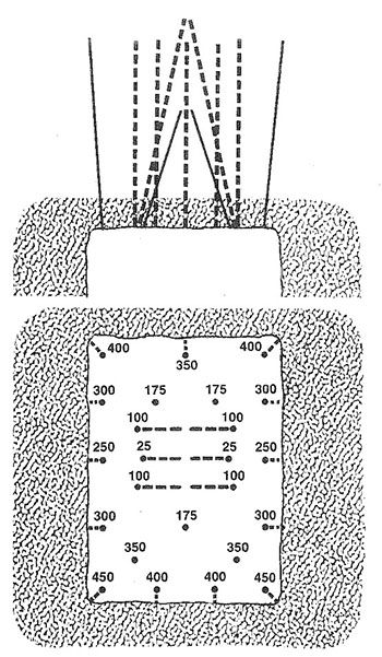
Here is a sketch of a bench, showing a few boreholes, and the design variables. This bench could be in an underground or surface mine. Our goal will be to calculate values for many of the parameters shown on this diagram.
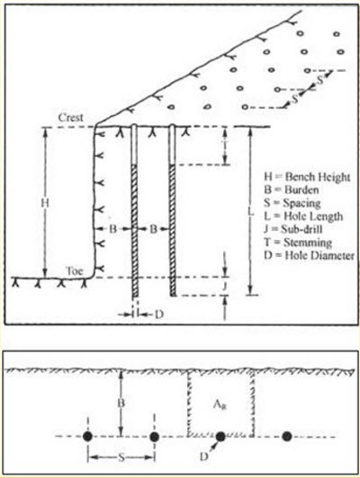
First, please take a look at each of these parameters, as labeled, and make sure that you understand what’s going on. There are two terms on the diagram that we have not yet defined. They are toe and crest. The toe is the bottom edge of the bench adjacent to the vertical wall. The crest is the top edge of the vertical or nearly vertical wall. This wall is often called the highwall.
The equations for determining the burden, spacing, and stemming require that we know the blast hole diameter. So, looking at the diameter of the hole is a good first step. This diameter is defined by the diameter of the drill bit.
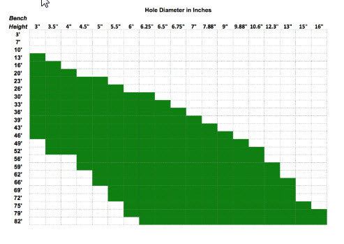
For benching, hole diameters typically range from a low of 3” to a high of 15”. If we’re benching in an underground mine, we’ll have hole diameters near the low end of that range, and for surface applications, we’ll be in the middle to upper end of that range. Just as a comparison, I would mention that for drifting, the holes are likely to be as small as 1-3/4” and probably no bigger than 3-4”. In many cases, you will have historical practice or the practices at similar mines to narrow your choices. Other times, you will already own equipment capable of drilling a limited range of sizes, and your design will be bounded accordingly.
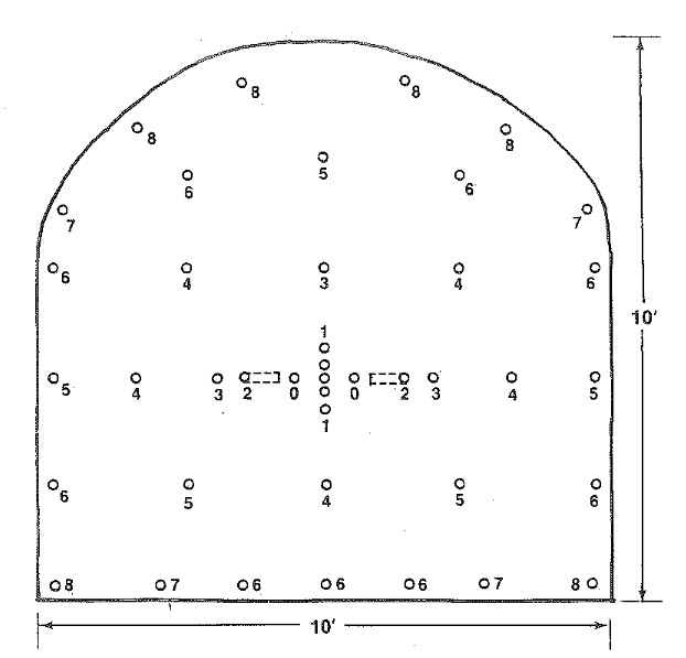
Here’s an interesting chart, which is a compilation of the hole diameter and bench height at more than a hundred mine sites. As you can see, there is a rough relationship between the bench height and the diameter of drill used to create the blast hole for that bench.
Given a hole diameter, D, we can calculate the burden, B, the spacing, S, and the stemming, T. We will use Ash's to calculate these parameters. Note, as indicated earlier, and as will become more apparent with the discussion of the “K” factors, these relationships provide guidance not absolute precision.
Let’s talk about these “K” factors.
KB = 20 for underground application and 25 for surface, assuming a standard ANFO and a rock density of approximately 2.5 g/cm3. If the rock density is significantly greater or less than 2.5, then the factor should be examined. Here’s a table of typical rock densities for commonly mined minerals. As you can see for most of them, the suggested KB of 30 to 25 will be fine. The notable exceptions would include coal and peridotite. If you need to convert these to lb/ft3, multiply by 62.3.
| Mineral | Rock Density |
|---|---|
| Andesite | 2.5-2.8 |
| Basalt | 2.8-3.0 |
| Coal | 1.1-1.4 |
| Diabase | 2.6-3.0 |
| Diorite | 2.8-3.0 |
| Dolomite | 2.8-2.9 |
| Gabbro | 2.7-3.3 |
| Gneiss | 2.6-2.9 |
| Granite | 2.6-2.7 |
| Gypsum | 2.3-2.8 |
| Limestone | 2.3-2.7 |
| Marble | 2.4-2.7 |
| Mica schist | 2.5-2.9 |
| Peridotite | 3.1-3.4 |
| Quartzite | 2.6-2.8 |
| Rhyolite | 2.4-2.6 |
| Rock salt | 2.5-2.6 |
| Sandstone | 2.2-2.8 |
| Shale | 2.4-2.8 |
| Slate | 2.7-2.8 |
If you are using an explosive, x, with a different bulk strength, the factor KB changes as follows:
KBx = KB * (BSx)1/2, and BSx is the bulk strength of explosive X.
The other two factors are constants: KS = 1 to 1.3; and KT =0.7.
And, that’s all there is to it! More or less… this gives us a reasonable first approximation to laying out the pattern, or at least the burden and spacing along with the stemming. There are additional considerations, as well as sources of additional guidance.
An important metric is powder factor, because it tells us something about how efficient our blast is, and if we know typical powder factors from other similar mines, we can use that number to back calculate some of our design parameters. Powder factor is defined as the weight of the explosive used divided by either the volume or weight of fragmented rock. Its units are lb/ton or lb/yd3, or in the metric system, kg/tonne or kg/m3.
The calculation of the powder factor is straightforward. In practice, you will know how many pounds of explosive were used and you will know how many truck loads of rock were fragmented; and frankly, it is a good idea to keep close tabs on this in your operation. In the design stage, you can directly calculate the powder factor.
The explosive charge per unit length of hole, Mc, is: , where D is the hole diameter and is the density of the explosive. The weight of the explosive in the hole is therefore the product of the charge per unit length and the charged length of the hole, Lc. Remember that the entire hole is not filled with explosive. For example, the top 1/3 or so may be stemming; and in this case, the charged length would be 2/3 of the hole length.
The volume of fragmented rock is taken to be the product of the blast area, Ab, around the hole times the length of the hole. It is defined by a rectangle with the hole in the center. The two sides of the rectangle are and . Or simply, the area of the rectangle, Ab, is the product of the burden, B, and spacing, S. The volume of broken rock is then the area, Ab, times the length of the hole. If we want the weight of the blasted material, we need to multiply this volume by the density of the rock that will be broken by the blast.
The powder factor, PF, is:
All right, we can calculate powder factor, and we understand why it is a useful metric to compute and monitor at our operation. Earlier, I mentioned that knowing factors at similar operations could be useful to us in the design stage. How so?
If we have a known powder factor to start with, we can use that to determine a reasonable burden or spacing, which could be a good “check” on our first round of calculations. We can calculate MC directly based on the explosive that we are going to use and the hole diameter. As a starting point, we can assume that Lc will be 70% of L. We know our bench height, so we know L. The remaining unknowns are B and S. Substituting, we have:
and simplifying,
, and rearranging,
You know MC and PF, but not B or S. However, you can compute the product of B&S; and then, you can choose one, and solve for the other. At this point, you may be thinking: but wait a minute! How is this helping me, because I still have to choose B or S. True, but you are not doing so blindly. You could use B that you calculated earlier with Ash’s formula, plug that number into this equation, and voilà, you now have values for B and S. Or better yet, rather than using the B that you calculated, you might refer to a handbook where you can find burden-to-spacing ratios for many different scenarios. For example, such a table may list a typical S:B ratio of 1.25 for the type of mine of interest to you. Thus, for this ratio:
Substituting this into the equation,
, and simplifying, we have: .
Solving:
And so, using “real-world" data for powder factor and burden-to-spacing ratio, we are able to estimate a reasonable starting point in our design. Please remember that the constant, 0.56, in this equation is only valid for this example.
Here are a couple of other things to keep in mind. The degree of fragmentation will depend on the interrelationship among powder factor, burden, and spacing. We could, as an extreme case, choose to drill one hole of say 48” in diameter and pack in with explosives. The number might look good in terms of the powder factor, but what is likely to be the outcome?
This is why it’s useful to calculate these parameters in different ways, using not only Ash’s formulas but also using the fundamental definition of powder factor and available handbook data.
Clearly, it's a bit of an art, and you will go through iterations before “perfecting” your design. Nonetheless, there is a solid scientific approach to get you reasonably close.
6.3.2: Drift Round Blast Design
6.3.2: Drift Round Blast Design
For drift rounds, we are talking about driving openings, i.e., drilling, blasting, loading, and hauling, in an underground mine. These openings are horizontal or nearly so in many cases, but can be on fairly steep grades in others. Think of advancing a tunnel through a mountain – we are driving an opening through the mountain, and depending on our needs, the tunnel may be inclined or nearly horizontal.
Although the calculations that we just covered are generally applicable, designing a blasting round for drifting is more difficult. There are two reasons for this. Primarily, it is because we only have one free face. In bench blasting, we almost always have at least two. Recall, what is happening in a bench blast. As we initiate the round, the blasted and expanding material closest to the highwall is able to move freely upward and outward in the direction of the highwall. When rock is blasted, it expands by 30% or more, so it needs somewhere to expand. Furthermore, the expanding gases from the detonation of the explosive are rapidly propelling this blasted rock. After the first row of holes has been fired and the fragmented material is moving out of the way, the next row is fired, and the round evolves in an orderly sequence based on the timing delays used in the pattern. If we don’t give the blasted material the space to expand and move, we’ll have a big problem. The fragmentation will be adversely impacted, of course, but the bigger problem is that the fragmented material will tend to stay in place, and then it will be very difficult to dig or load. This is the challenge we face in drifting, because we have only one free face.
We overcome this limitation by creating a second free face; and we do this by putting cut holes in the center of the opening that we are driving. We’ll look at these cut holes in the next lesson, but, essentially, they are unloaded holes drilled in the center of the center of the opening; and then, when this new free face is created, we set off the remainder of the holes. The blasted rock from those holes is then free to expand inward towards this new free face that we created in the center of the opening, and then outward.
We can use the same formulas for drift rounds as we did for designing a blast round for a bench. However, the patterns will be significantly different. And that’s what we really need to look at next – the patterns, i.e., hole placement and timing delays that are used in bench and drift blasting. We’ll do that in the next lesson.
Before moving on to that topic, let me finish one last detail here. I said that drift blasting was more challenging for two reasons, and we just talked about the primary reason for this. The other reason is overbreak, which is fragmentation that occurs beyond the intended space. Suppose you were blasting a tunnel with a rectangular cross-section of 30’ wide by 20’ high. Your goal will be to limit fractures in the rock to the 30’x20’ opening. It’s unlikely that you could maintain a perfect opening, but limiting the fracturing beyond those boundaries to less than several inches is doable. We aren’t as particular about this in many surface applications as we are in underground mines. Why? We touched on this earlier.
These fractures are likely to become future ground control problems, costing us time and money. The fractures or cracks are likely to destabilize over time, and if there is ground water seepage, the process will accelerate. Accordingly, we have to design a round to minimize overbreak. Unfortunately, few engineers do this for lack-of-knowledge; but it is not that difficult, and we will learn how to do it in the next lesson.
Lesson 6.4: Blasting Patterns
Lesson 6.4: Blasting Patterns
We have learned much about explosives, as well as some analytical procedures to help us design blast rounds in surface and underground mines. We know that a blast round consists of multiple holes arranged in certain geometric patterns, and we know that the holes are not necessarily fired at the same time. We don’t know much about these geometric patterns for the holes, nor the time delays that may be used. You will recall from the first lesson of this Module, we watched the video clip, “Dance of the Detonators,” and we saw vivid evidence of different patterns and the use of timed shots. In this lesson, we’ll look at some common patterns, talk about their use, and we’ll look at delayed firing of holes, including the various technologies available to use for this purpose.
6.4.1: Patterns for Drift Rounds
6.4.1: Patterns for Drift Rounds
The overall pattern will be based on the desired shape of the blasted opening. If we are driving headings that will be used by people and equipment to access the ore and conduct the mining operation, we will strive to create openings that will be stable over time, and be of dimensions that meet certain requirements. These requirements may be openings of a minimum height and width to allow equipment access, or the dimensions may be based on production requirements. And there could be other considerations. Rectangular openings have sharp corners that tend to concentrate stresses, whereas elliptical or circular openings do a better job distributing the stress around the opening, and as such, they are more stable. The strength of the rock and the expected life of a particular opening will influence the shape as well as the dimensions of the opening.
The cross-section shown here is typical, but regardless, the content that we are going to cover applies to other shapes as well. Notice that the cross-section is divided into named regions. This can be applied to cross-sections of almost any size and shape.
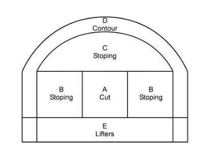
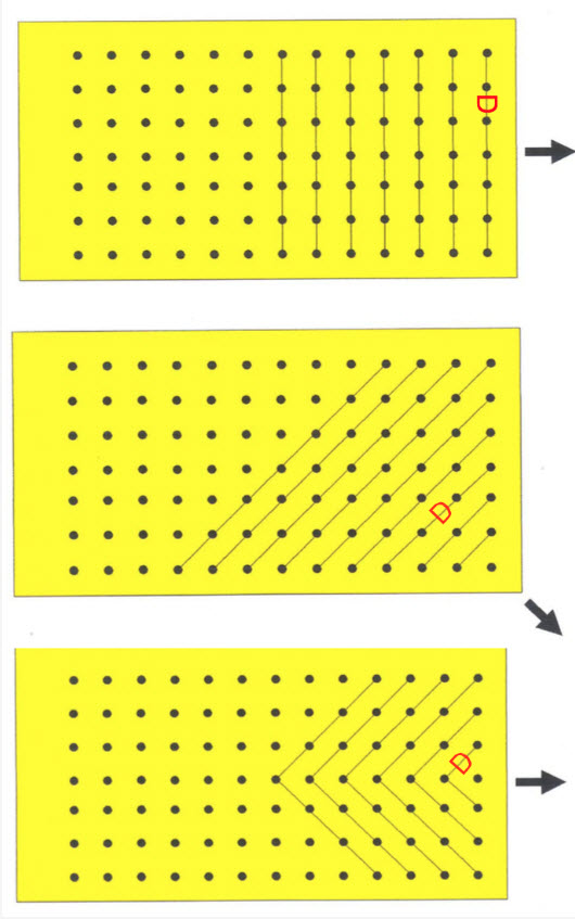
The purpose of the Cut is to create a second free face, which we introduced in the last section of this lesson. There are two general types of cuts: parallel cuts and angled cuts.
The most common type of parallel cut is known as the burn cut. Burn is the shortened name for the Viburnum Cut; so-named because it was developed for use in the lead-zinc mines found in the Viburnum trend in Missouri, back in the 1950s. Its use quickly spread to many underground mines. The burn cut consists of parallel holes, sometimes of different diameters, and always some of the holes are unloaded. The unloaded holes within the burn are referred to as relief holes. Sometimes, a few angled holes are placed within the burn, but this shouldn’t be confused with the other major type of cut, i.e., the angled cut.
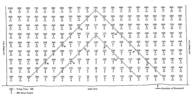
Here are examples of burn cuts. The loaded holes are shaded black. The numbers adjacent to the hole refer to the firing sequence. The spacing between the holes is shown for most of them, although the diameter is not. The diameter of the holes would be the same as used for the other regions of the pattern, with the possible exception that the unloaded holes are occasionally of larger diameter. For example, if the loaded holes are around 2”, the unloaded holes of the burn cut may be 4”.
The unloaded holes provide an initial, although quite small, free face. The holes labeled “1” are fired first. The expanding rock moves toward the center and also out in front of the free face. The result is an expanded second free face, and the holes labeled “2” are then fired. They have the benefit of the larger free face, and after they have done their job, there is a sufficiently large free face in the center for the other holes to be fired.
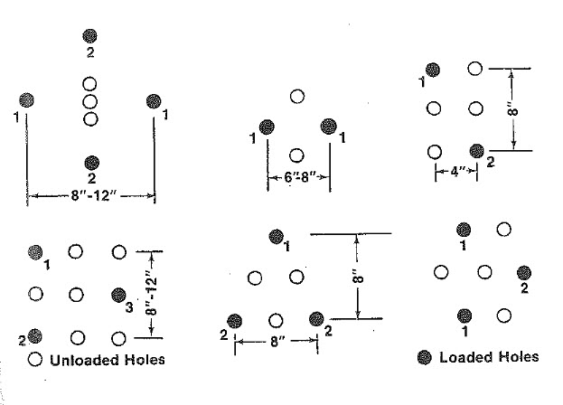
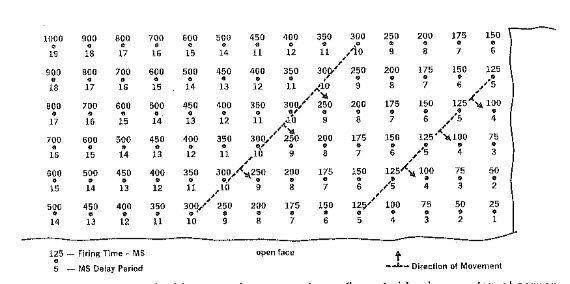
Here is an example of the most widely used angled cut, which is known as the V-Cut. All of the holes are loaded with explosive, which is a contrast to the burn cut. The V-Cut shown here includes a baby V, which is also fairly common. The number adjacent to the holes designate the millisecond (ms) delay for the firing of that hole.
In this example of the V-cut, the baby V fires first, and creates a small free face for the firing of the two large Vs. Then, after the two large Vs have fired, there will be a sufficiently large free face to fire the remainder of the holes. Other variations of angled cuts include pyramidal and diamond-shaped arrangements.
A particular cut will tend to give better and more consistent results in a given deposit. Most underground limestone mines, for example, will settle on a V-cut after trying the burn and V-cuts, whereas in the lead mines in Missouri, there is a decided preference for the burn cut. One of the more important deciding factors will be the pull that can be achieved with the round. Pull refers to how far back into the face you can successfully blast. If we drill a hole, say 12’ back into the face, can we get good fragmentation at the back end of the hole? As you attempt to drill further and further back into the face, it becomes increasingly difficult to achieve good fragmentation near the back of the hole. The distance that you can achieve good fragmentation is known as the pull. It’s important to monitor the pull closely because if a problem has crept into your workflow, whether it is a change in the geology, an inexperienced driller or blaster, or other problem, it will often show up first as a reduced pull.
The stoping holes do most of the work of advancing the face, as they blast the most rock. These holes will begin to fire as soon as the cut holes have cleared, and they will fire in a sequence such that the holes closest to the cut will fire first, and then those further away will fire in sequence. The idea behind the sequencing of the stoping holes is to ensure a good free face for the blasted material to move through.
Lifters are not always used, but their purpose is to help ensure good fragmentation at the bottom of the drift, as this will allow for an even surface that will facilitate movement of people and equipment through the drift. Lifters can also help to throw the blasted material out into the drift to improve the ease of loading.
The holes in the Contour region are designed to ensure a smooth surface and to minimize overbreak. The contour region is properly defined by two rows of holes. The inner row is known as the buffer row, and the outer row at the perimeter of the opening is known as the contour row. Research completed in recent years provides design guidance on how to minimize overbreak using the buffer and contour rows. However, this has yet to be widely adopted.
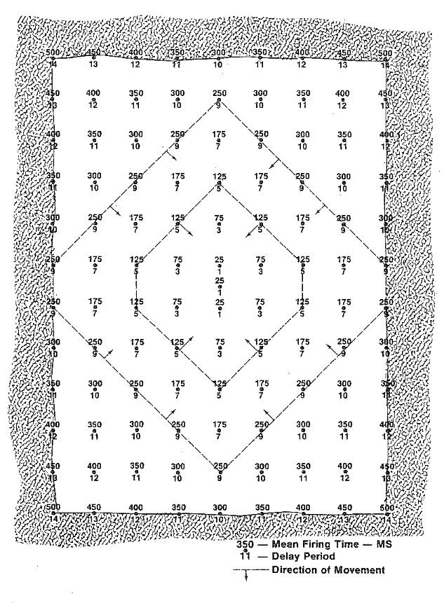
The delay sequence for a drift heading using a burn cut is shown below. Note that the burn has two angled holes; and also note that the contour region only has one row of holes around the perimeter, reflecting the longstanding practice.
The process of minimizing overbreak is referred to as controlled blasting and is documented in the following publication: NIOSH Report of Investigations 9691, A New Perimeter Control Blast Design Concept For Underground Metal/Nonmetal Drifting Applications [5], Stephen R. Iverson, William A. Hustrulid, and Jeffrey C. Johnson.
We are not going to go through the details of the design in class, but I want you to understand conceptually the process. You have the publication that you can use in the future to design a controlled blast.
This approach requires that significantly more holes be drilled and loaded than in the traditional approach. However, it is rarely about first costs only! You have to look at costs over time, and then make an informed decision. While the first costs of this approach are higher, the improved ground control should yield larger savings over time by eliminating the extensive damage zone into the back and walls.
This approach allows a burden to be calculated between the buffer row and contour row, such that the damage radius from the buffer row does not extend beyond the contour row.
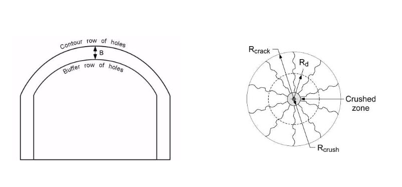
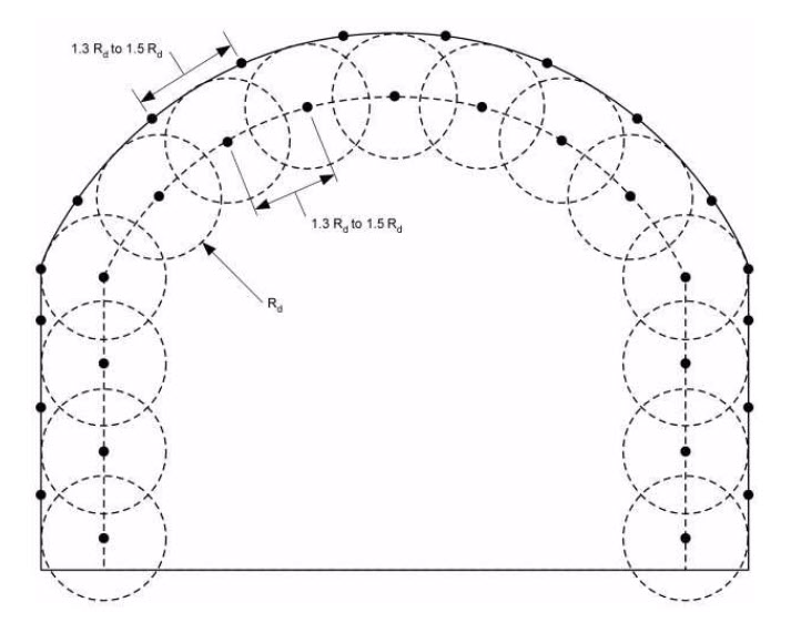
The spacing of the buffer and contour holes is based on the damage radius, Rd, as shown here.
After the buffer and contour holes have been located, the lifters are added. Next, the cut holes are placed, and then, finally, the stoping holes are located. Design guidance for these holes is given in the report.
It is important to note that the contour holes are very lightly loaded. The function of these holes is to trim the wall at that point, not to create additional crushing and fracturing. This is known as decoupling of those holes. There are various ways to load these holes to achieve the desired effect. One way is to use a detonating cord in the hole instead of a blasting agent such as an emulsion or ANFO. Another is to use trim cartridges, i.e., products specifically developed for this purpose.
I think I’ll close this discussion on blast rounds for drifting by showing you a short video clip. The blast will be repeated several times. You’ll want to try to determine the type of pattern that is being used, based on your observation of the detonating cord.
6.4.2: Patterns for Bench Blasting
6.4.2: Patterns for Bench Blasting
There is a seemingly endless variety of patterns, and to make sense of it all, it’s helpful to remember that when all is said and done, the design goal is to achieve uniform fragmentation within a certain size range, and to do this it is necessary to ensure an adequate free face. Most of the variation that you will see in the patterns, and especially for surface mining, will be as result of the way in which the free faces are created and managed. The patterns for an underground bench blast tend to be straightforward – the amount of explosive that will be set off will be far more limited than in almost all surface mine blasts. As you attempt to blast larger and larger volumes, you need more holes, more rows, and the timing delays become more involved.
Here is a common surface mine layout with one free face. The numbers underneath the hole correspond to the delay sequence, first, second, third, and so forth. The numbers over the holes represent the millisecond delay for that hole.
If there are two free faces, as in this case, a pattern like this is common.
Occasionally, it is necessary to design a surface blast where there is no free face. Imagine an open field, and you are going to make the first blast so that material can be removed to initiate the surface mining cycle. By the way, the name given to this is box cut. Box cuts are a common means of accessing an orebody for underground mining, when the deposit is within a few hundred feet of the surface; and they are required as one of the initial development steps in most surface mining operations. A blasting pattern for a box cut is shown here.
These patterns can and will be modified ad nauseam to account for local geological anomalies, nearby structures such as pipelines or buildings and so on. With the few figures that we’ve examined here, you really do have comprehensive starting point for the design of your own pattern. You know how to: determine the burden, spacing, and stemming; choose an explosive or blasting agent; and lay out a pattern. One glaring gap in your knowledge base is how to achieve the desired timing delays. And so, we need to talk more about initiating the blast and the technology options available to us. We’ll do that in the next lesson.
Lesson 6.5: Fire in the Hole
Lesson 6.5: Fire in the Hole
Prior to setting off a blast, the blaster would yell, “fire in the hole – fire in the hole – fire in the hole.” This still occurs today, but not as frequently because loud sirens or whistles are often used instead. After the annunciation, whether by voice or siren, the blaster throws the switch or depresses a plunger to set off the blast. Or, in the good days, a third option would have been to strike a match or light a fuse! But what is going on here?
We know that we need an “initiator” to set off an explosive, something like a blasting cap for example. However, we also know that many of the blasting agents in common use today are not cap sensitive, and consequently, we need to use a primer. The cap, or whatever initiator we use, sets off the primer, which then sets off the blasting agent or explosive. Finally, you will recall that there are times when we are concerned that the explosion will not continue due to the length of the explosive column or the use of decking, for example, and in those cases, we add boosters. And in some cases, we will actually have multiple boosters in the hole.
We’ve talked at length about explosives. Now, let’s spend some time with initiators!
6.5.1: Initiation of the Blast
6.5.1: Initiation of the Blast
Initiators contain high explosives that will detonate upon receiving an appropriate “signal.” If the blasting agent is cap-sensitive, then this action will set off the explosion. If it is not cap-sensitive, then the initiator will set off a primer, which will set off the blasting agent. In a typical pattern, there are many holes and each will have an initiator, and all of these holes need to be connected together, and a line must then be run to a safe location where the blaster will “throw the switch.”
Let’s talk about these initiators, their connection back to the blaster, and the method that the blaster uses to start the chain reaction.
Initiators can be classified into three categories. The categories and their primary characteristics are as follows:
- non-electric (75% of market and decreasing):
- immune to stray electricity,
- water is less of a problem than with other types,
- modest cost advantage, i.e., lower cost than other types;
- electronic (20% of market and increasing):
- allows for precise timing and sequencing,
- enhanced site security,
- immune to stray electricity,
- higher first cost and more complicated to use;
- electric (5% of market and decreasing):
- historically offered better control of timing and sequencing over non-electrics,
- simplicity in use,
- lack of site security,
- susceptible to stray electricity.
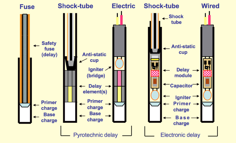
Non-Electric Initiation
The predominate non-electric system uses shock tube and a non-electric blasting cap. Shock tube is plastic tube with a thin coating of a high explosive (think of a plastic drinking straw in which the inner wall of the straw has a thin coating of high explosive). Specially made plastic block connectors are used to join different lines (shock tubes) together; and, if desired, delays can be inserted at these connector blocks as well. Shock tube is set off with a machine that creates a spark or a mechanical device such as a spring-loaded hammer that strikes a starter resembling the tiny button primer at the base of a shotgun shell. Today, shock tube is used almost exclusively within the non-electric category. I don’t want to unnecessarily confuse the issue, but be aware that the nonelectric blasting caps used with shock tube can contain a pyrotechnic or an electronic time-delay mechanism within them. We’ll discuss blasting caps, both non-electric and electric, shortly.
Detonating cord contains a high explosive, such as PETN. It was used for trunk lines and downlines. Lines can be simply knotted together. It is initiated with a blasting cap (electric or nonelectric). The detonation velocity of PETN is 27,000 fps, and it creates a huge air blast. This is a big problem, and as a result, detonating cord has been largely replaced with shock tube.
There are two other types that no longer used in modern operations, but it's interesting to know what they are in case you read or hear about them. They are safety fuse and igniter cord. Allow me to tell you a bit more about safety fuse.
- Safety Fuse is a thin cloth fiber cord with a black-powder core. It has a uniform burn rate, for instance120 sec/yd. By varying the length, you could vary the time delay. Safety fuse was used to set off dynamite. It was also used in a lot of bad old cowboy movies in which a bad guy tied the good guy to a powder keg, and the powder keg was connected to a very long safety fuse. The bad guy lit the safety fuse and rode away. Since the safety fuse burns so slowly, the viewers got to watch it burn for a few minutes, giving the hero just enough time to swoop in and extinguish the safety fuse before it set off the powder keg!
Electronic Initiation
The popularity of electronic initiation is increasing because this system offers significant performance and safety advantages over other systems.
- Electronic caps consist of an electronic chip, a small capacitor, and a high explosive to detonate a primer or a cap sensitive explosive.
- Each electronic cap has a unique serial number with a bar code.
- Electronic caps are wired into the blasting circuit with insulated copper wire.
- An electronic blasting machine is required, and it communicates digitally with each cap.
- The electronic blasting machine is programmed to send a “fire” signal to each cap, based on the cap's serial number, according to a user-determined firing pattern.
- The wired circuit connecting the electronic caps together and to the blasting machine also carries an analog voltage to charge the capacitor in each cap. Charging of the capacitor begins after the blasting machine has “authorized” the cap to fire. The capacitor provides the energy to detonate the high explosive within the cap assembly. The authorization to each cap is possible because the unique serial number of each cap is known. The blaster can use a tag reader to record the serial number of each cap as each hole is loaded. This data can then be downloaded to the blasting machine.
- The time delay is determined electronically on a chip, and this is known as an electronic delay.
- The more precise timing and sequencing can be used to minimize ground vibration as well as to improve the outcome of the blast…but only if the underlying shot design is correct. The improved blasting performance available with an electronic initiation system will offset the higher initial cost of the caps.
- This system affords the user with a high degree of site security – a cap cannot be set off without a special machine and knowledge of the cap’s serial number.
It should be noted here that there is a type of electronic blasting cap that is made for use with shock tube, and that cap offers the advantage of more precise timing, but it does not offer the other benefits inherent to an electronic ignition system.
Electric Initiation
For decades, electric blasting caps were the only choice if you wanted to control more exactly the time delays. However, their susceptibility to stray electricity (think cell phones, two-way radios, and approaching electrical storms) has led to their rapid decline.
- Electric blasting caps have a bridge wire inside of them, embedded in a high explosive. When current from the blasting machine, or stray electricity, flows in the network of copper wires, the bridge wire melts, igniting a column of powder that controls the delay time, which then sets off a high-explosive base charge. This is known as pyrotechnic ignition. The base charge sets off a cap-sensitive blasting agent or a primer.
- The blasting circuit consists of many wires connected in series and in parallel, e.g., leg wires and trunk wires. A circuit analysis must be performed to ensure that sufficient current will be available to ensure a reliable blast.
The following diagram can be very helpful to solidify your understanding. The two different delay options, i.e., pyrotechnic and electronic, can show up in different initiation systems. That is sometimes confusing when you are learning this for the first time. Thus, it really is helpful to examine this diagram until you understand the operating principles and why they are named the way they are.
Historically, time delays were used to control the orderly movement of material through the free faces, as we have discussed; or to limit the amount of explosive being fired at any one time, which reduces the level of ground vibration. The advent of electronic initiation ushered in a new era in which we could more effectively take advantage of the physics.
Traditionally, time delays were available in 25 ms delays, which is adequate for the purposes that time delays have been used. The p and s vibration waves are shown in this figure for two cases: the first using traditional delays; and the second, using electronic delays that allow timing down to 2 ms. This allows us to create a positive interaction with the shock waves, and this gives us improved fragmentation.
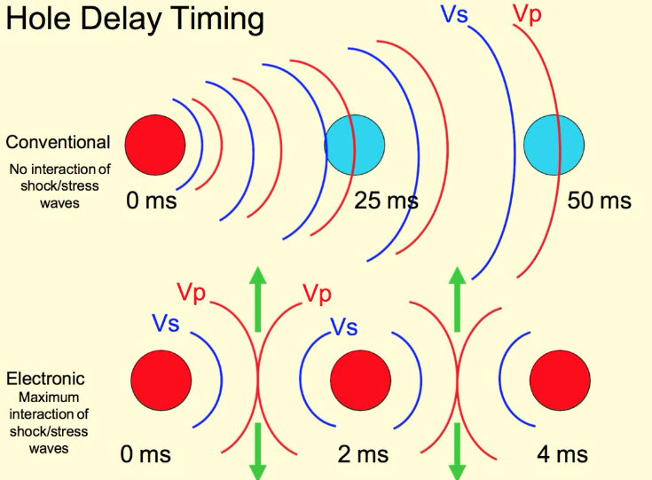
It can be shown that the time delay, T, required between holes in a row is:
where:
T = the time delay between holes in a row, ms
S = distance between holes in a row, ft
Vp = compression or sonic wave velocity, ft/s
The row spacing distance used in the equation is the effective spacing, as shown for three different cases here. Note that the definition of a “row” is based on the firing sequence.
The value for Vp can be estimated from tables or by seeking advice from geophysical consultants. The value for Vp not only depends on the type of rock, but also the rock mass characterization. There are a few different characterization schemes in use, such as the Rock Quality Designation (RQD) or the Rock Mass Rating (RMR), but, in general, they take into account the number and spacing of the joints, the competency of the rock, and other characteristics of the rock mass. If you want a number for Vp so that you play with the equation, use 10,000 fps.
The potential for using electronic initiators to take advantage of the wave interaction is just being realized, and will become more common in the future. You now have knowledge of this, and can choose to take advantage of it in your future work.
Earlier in this lesson, I mentioned the idea of limiting the amount of explosive detonated in a given delay interval to lessen the impact of ground vibration. I’d like to look at that in more detail at this time.
6.5.2: Limiting Ground Vibration - Scaled Distance
6.5.2: Limiting Ground Vibration - Scaled Distance
Humans are very sensitive to vibrations and can perceive extremely low levels; and while this may have been an invaluable survival skill a long time ago, today it creates problems for mining and construction companies wanting to conduct blasting as part of their operations. Please don’t misunderstand me: I am not suggesting that we should blast in a way that causes any property damage. Unfortunately, the difference between the level at which people “feel” vibration and the level at which damage occurs is large. Consequently, when people feel vibration, they assume the worst. They look around the house and see a picture on the wall that is no longer straight. Had to be those vibrations! They look more closely, and they see some fine cracks in the plaster on the wall. Well, that’s it; we’ll have no more of this, they’re going to bring down our house!!! Then the angry phone calls, letters, and confrontations with company officials begin. Sometimes, citizens groups emerge, and usually local and sometimes state officials become involved. Mining companies spend more time and money dealing with this than they should! Oh, and when I say mining companies, I mean YOU. If you go to work in a surface mine, chances are good that in your first few years on the job, you will deal with this. So, what’s a person to do?
I have five recommendations.
- First, and foremost, you have to get the engineering right! You have to design your blasts correctly. We’re going to learn how to ensure that the ground vibration levels from your blast are below levels that could create any damage.
- Second, you have to ensure that the drillers and blasters are executing the blast as you designed it.
- Third, you need to be “smart” about when you blast. Most surface mines that are in close proximity to neighborhoods blast once a week. You’re likely to create fewer problems with the neighbors if you blast late morning or early afternoon on a weekday. Blasting around dinner time is a bad idea, as is shooting a round on the weekend!
- Fourth, you and your company should work to have a genuine and positive relationship with the community, as we discussed way back in Module 1. That will help you to navigate these kinds of issues, and, moreover, you may need to spend some time educating the locals on this topic. In fairness to them, they feel the vibrations and they are worried that you are going to damage their house. If they were structural or mining engineers, they wouldn’t be concerned, but they are not, and they are concerned! Educate and inform!
- Fifth, you should give serious consideration to contracting with a consulting geophysical firm that specializes in blasting vibration. They will help you to set up a seismic monitoring program and provide other guidance. Sometimes, neighbors will file damage claims, or raise regulatory issues; and this will happen even though you are certain that the vibration levels were well below any damage threshold. Obviously, you want to ensure that you are not actually causing a problem, but beyond that, you’ll want to establish a paper trail to document that you’ve been doing it properly, and that you could not have caused the loss that is being claimed. And, that's where a geophysical consultant can be a big help to you. There is a company based here in Pennsylvania known as Geosonics / VibraTech. They provide services internationally and are active with our Department and our chapter of SME. I recommend that you peruse their website to get a better feel for the type of services that mining companies use. Here is the link: GeoSonics/Vibratech [6]
Now, I want to focus on the engineering.
Ground vibration at a remote location is a function of the amount of explosive set off within a short time period (a few ms) and the characteristics of the rock mass between the blast holes and the remote location. You cannot change the local geology, and if you are mining stone, for example, it is a safe bet that the rock in your quarry is solidly coupled with the surrounding community; and as a result, any vibration that you create will travel quite well through that bed of limestone to the surrounding neighborhoods.
You can’t change the rock mass. That leaves the amount of explosive fired in a short time as the parameter that you can control. An explosive works by creating shock waves and gas pressure. The more explosive that you set off, the larger the shock wave, which travels through the coupled rock mass, and causes ground vibration. So, by limiting the amount of explosive set off at any one time, you can limit the shock wave. Within a few thousandths of a second, the shock wave will have dissipated, and then you can set off the next group of holes. Earlier, we talked about using time delays to create and effectively use the free face(s). Now, we’re adding a second reason for using time delays in a blast round -- to limit ground vibration (and also airblast).
We characterize the shock wave by its peak particle velocity (ppv) and the frequency of the wave. Both are important, but most of the attention is given to the peak particle velocity. Rattling of windows and dishes, or cracks in a wall can be related to the peak particle velocity. The design question for us is, how much explosive can we fire at one time without exceeding the threshold ppv value at the nearest structure?
We could model the rock mass and use sophisticated geophysical models to predict the level, and there are a few instances where such an effort would be warranted. For example, if the nearest structure is a building that has a piece of multimillion-dollar lab equipment that is extremely sensitive to low levels of vibration, then, we’re going to call in expert consultants, e.g., Geosonics, to perform the analyses. Fortunately, in most cases, we can use engineering approximations. These are normally very conservative, and after we gain some experience with the pattern, we may be able to increase the amount of explosive per time delay with no adverse impact on neighboring structures.
The U.S. Bureau of Mines developed an approximation method, known as scaled distance, to estimate the amount (weight) of explosive that would produce a certain ppv at a specified distance. Over time, this method has been adopted by state and federal regulatory agencies, and these agencies have regulations that require that ground vibration be limited based on either the scaled distance or the peak particle velocity of the shock wave. Usually, you would use the scaled distance to calculate the amount (weight) of explosive that can be fired without exceeding the statutory limit, which is typically a peak particle velocity of 0.5 in/s.
The Bureau of Mines (USBM) conducted hundreds of tests at different surface mines. The sites and surrounding areas were heavily instrumented to record the amplitude and frequency of the vibrations from blasts of varying size. Eventually, they developed a relationship between the peak particle velocity and a quantity they defined as scaled distance.
The scaled distance, S, is a function of the distance to the nearest structure, D, and the charge weight, w, fired within an 8 ms interval.
The units for D and w are ft and lb respectively. The unit for scaled distance, S, is therefore
Rearranging the equation to solve for the charge weight:
If you know the distance to the nearest structure and the scaled distance, you can calculate the charge weight that can be detonated in one delay period without exceeding a particular vibration level. So, let’s look at a plot describing the relationship.
This is a plot of the USBM data points, and each point is defined by the measured peak particle velocity (ppv) and the scaled distance. A good correlation exists as shown. They are actually plotting data from three different geophones, i.e., seismic sensors. The line of interest to us is the one labeled “vertical” because it represents the ground vibration level of interest to us at the structure we are trying to protect.
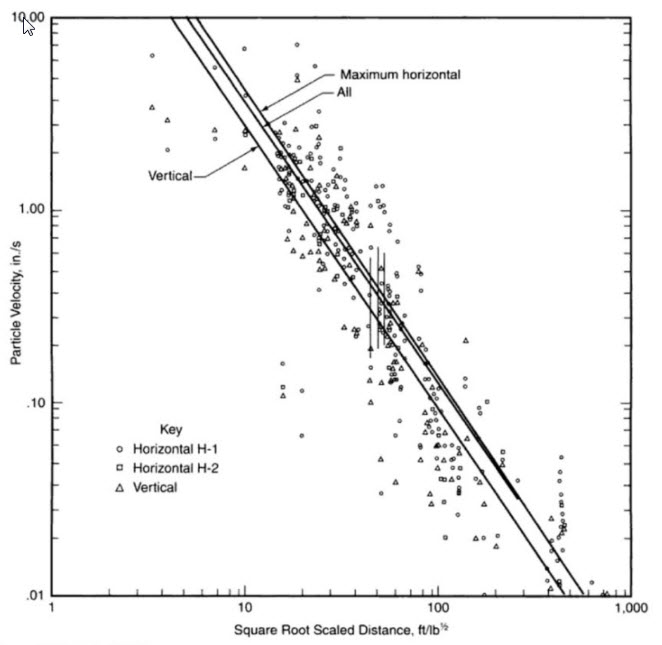
To continue with our example, let’s say that the nearest structure, which we do not own, is 2500’ from the bench that we are going to blast. The statutory limit for this mine is 0.5 in/s. What is the maximum charge weight per delay period?
Maximum charge weight/delay period:
The computed value for w is the total weight of explosive that can be detonated within a prescribed delay period, which is typically 25ms. Based on the amount of powder in each hole, you can then calculate how many holes can be fired at one time. Suppose, for example, that each hole is 5” in diameter, 45’ deep, and requires 10’ of stemming; and you are using ANFO with a density of . How many holes could you fire at one time, without exceeding the prescribed vibration limit?
The charge weight per foot of hole =
The charge weight per hole =
The maximum number of holes per delay period =
= 9.9 holes.
How accurate is this estimate? We need to understand the assumptions underlying the scaled distance chart. The chart is based on the use of a dry ANFO. If a more energetic blasting agent or explosive is used, the chart will overestimate the amount of powder that can be fired at one time. The USBM field sites were predominantly surface coal mines and some quarries. Depending on the local geology, the chart will overestimate the amount of powder. An overestimation of the amount of powder translates directly to an increase in the ground vibration level, which could put you in violation of state-regulated maximum levels. So, what good is this approximation if it can lead to significant overestimates? Simply, it provides a good starting point for your design. Further, in Pennsylvania for example, the state agency requires you to start with a scaled distance of 90. It is unlikely that you would ever have to worry about an overestimation at that distance!
Our discussion has focused exclusively on ground vibration. A similar approach is used to limit airblast. A different chart is used becuase the relationship between air blast and distance is cubic rather than squared. If we were to use the companion chart for airblast, we could go through an almost identical process to determine how many holes could be fired within a delay period without exceeding the airblast threshold. We’re not going spend any time doing that, but if you have the need at a future time, I am sure you could do that without any problem!
OK, let’s recap the engineering design of the blast round, as described in the recent lessons.
- The design is guided but not fully defined by science. Practical experience is invaluable in optimizing the design. If you don’t have that experience, the people who sell blasting products often have a wealth of practical knowledge and are happy to share it with you. Of course, they will be hoping for your business!
- The design process is iterative. You start out assuming certain parameters and calculating others. You compare the numbers that you are generating with handbook or literature values. Then, you rework some of those initial calculations with modified values, which generates results more aligned with the practical experiences of others. In particular, you will likely start by establishing values for the hole diameter, the burden, spacing, and stemming. Likely, you will locate typical powder factors and burden to spacing ratios in similar applications. You may then “fine-tune” your burden and spacing values, and perhaps reevaluate the diameter of your borehole.
- You will lay out the pattern of the holes based on free-face requirements, and you will assign holes to specific delay intervals.
- If you are blasting in proximity of structures that must be protected, you will assess ground vibration and airblast potential. It is likely that you will then alter your timing to limit the number of holes that fire within a given delay period.
- A reasonable next step would be to drill some holes and evaluate your design, keeping in mind that even if you are completely satisfied with the outcome (highly unlikely), you should be evaluating the outcome of your blasts on a regular basis, day-after-day, week-after-week, and month-after-month!
- We saw earlier in this lesson that you can use the precise timing of electronic delays to further improve fragmentation, and probably with less explosive. If you were going to pursue that in your design, you would then calculate the appropriate delay between holes in the row. Keep in mind that these delays would all occur within the large delay period that is based on managing your free faces and limiting ground vibration or airblast.
- There will be other reasons why you will need to modify your design over time. If you are experiencing fragmentation issues with cap rock, for example, you will utilize a set of design criteria to resolve them. If there is a big mud channel or fault running through your property, it will necessitate serious changes in your design. Those details are well beyond the scope of this course, but with your engineering fundamentals background and the knowledge that you’ve gained here, you’ll be able to handle those problems as they arise.
In the next module, I am going to show you photos taken at mine sites around the country to illustrate many of the basic concepts that you’ve studied in this module.
Module 6 Summary
Module 6 Summary
Blasting is an important part of almost every mining method, and the responsibility to design a safe and effective blasting pattern lies with the mining engineer. There are a variety of blasting agents and technologies available to accomplish the task, but they must be selected and applied correctly. As we saw, blasting is both an art and a science. The science guides our design, but in the end, experience and judgment will allow us to optimize the outcome. Importantly, we saw that the skill of the drillers and blasters will affect the outcome of the blast. Errors or carelessness in drilling and loading, for example, can cause terrible outcomes. Changes in the local geology can quickly change the outcome of the blast, and these changes are usually not for the better! It is therefore essential that the mining engineer follow up on a regular basis to inspect the outcome of the blasts, and to make changes to the design or implementation. The cost of drilling and blasting is significant, and you will want to take steps to ensure that you are controlling these costs. Do not forget, however, that your blasting practice can significantly influence your overall productivity by affecting other auxiliary and unit operations ground control to loading. Inspection, measurement, and calculation of your blasting outcomes, on a frequent and regular basis, is important!