Module 7: Surface Mining
Module 7 Overview
Module 7 Overview
The vast majority of minerals, by tonnage and type, are recovered from surface mining activities. As you know, surface mining is used to recover near-surface mineral deposits, where it is economically feasible to remove the overburden to gain access to the minerals of interest. Surface mining is typically a large scale and bulk operation. In general, the surface mining methods are the lowest cost of any mining methods. Of course, some minerals of economic interest lie too deep to be economically recovered by a surface method, whereas others cannot be mined by a surface method because of environmental or social constraints, which necessitate using an underground mining method to recover those deposits.
Let’s take a look at the number of surface vs underground mining operations for each mining sector in the US.
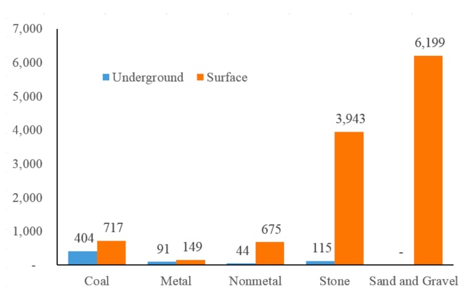
Click to expand to provide more information
| Sector | Underground | Surface |
|---|---|---|
| Coal | 404 | 717 |
| Metal | 91 | 149 |
| Nonmetal | 44 | 675 |
| Stone | 115 | 3943 |
| Sand and Gravel | 0 | 6199 |
Not only are there more surface than underground mines, but also the average productivity is higher for surface operations. The average productivity (average tons per miner per hour) for surface mining is around three times the value for underground mining. Here is a summary of coal mine productivity for different years (the values are tons per miner per hour) to illustrate the difference in productivity, as well as changes that have occurred over the years.
| Year | Underground | Surface | All Mines |
|---|---|---|---|
| 1980 | 1.21 | 3.27 | 1.93 |
| 1990 | 2.54 | 5.94 | 3.83 |
| 2000 | 4.15 | 11.01 | 6.99 |
| 2010 | 2.89 | 9.47 | 5.55 |
| 2015 | 3.45 | 10.95 | 6.28 |
The depth and breadth of engineering required for surface as compared to underground mining is arguably significantly less. Nonetheless, good engineering is the key to sustainable operations; and it all begins with mine planning.
Learning Outcomes
At the successful completion of this module, you should be able to:
- demonstrate knowledge of the goals of long-range, short-range, and production planning;
- demonstrate an understanding of the Mathieson list of objectives for the extraction planning process, and explain in specific terms how those objectives would affect planning and mining activities;
- lay out a bench for an open pit mine, labeling the toe, crest, the face angle, bench width and height, face angle, slope or pit angle, and the berm location and height. Describe the parameters and considerations that will affect the design of the bench;
- demonstrate knowledge of the mechanical and aqueous surface mining methods, and specifically for each method:
- describe the factors that favor the choice of the method over other methods,
- describe the life cycle and sequence of operation,
- sketch the method to illustrate its defining characteristics,
- list the type of equipment normally associated with the method, and
- name examples of commodities that are commonly mined using the method.
Lesson 7.1: Mine Planning
Lesson 7.1: Mine Planning
We are going to talk about mine planning in this lesson, and the focus is on surface mining. However, almost everything that we cover is equally applicable to underground mine planning, even though the examples that I use here are taken from the surface rather than the underground application.
What do we mean by mine planning, and why do we do it. As to the first question, mine planning is a combination of mine design and scheduling of mining activities. The short answer to the second question is: we need to align our mining activities to meet the financial expectations of the company or its investors. We’ll look at both of these in more detail.
Mine planning involves both mine design and scheduling of mining activities.
The goal of mine design is to create a mine that will allow exploitation of the reserve in a safe, economic, and environmentally responsible manner. This design will reflect the unique characteristics of the deposit, anticipated market for the product, and the profit expectations for mine.
Mine scheduling, on the other hand, is concerned with the sequencing of operations and the assignment of equipment and people to ensure that the intended sequencing and production targets are realized. For example, if you dispatch an electric shovel and trucks to remove ore, but the dragline has not yet removed the overburden overlying the ore, you will have a problem… and you will probably be out of a job! Mine planning is performed over many different time horizons. When you are doing your initial feasibility study, you will look at a life-of-mine time frame, which might be 30 years, and as your planning progresses, you will focus more on the first five years; and once the mine is open, you’ll be looking at time frames as short as this shift or the next few shifts. Not only is mine planning an on-going activity, but the planning for the different time horizons is ongoing.
This can be summarized in the following table:
| Type of Plan | Cycle for Updating the Plan | Period Covered by the Plan |
|---|---|---|
| Long-term | Annually | Life-of-mine |
| Medium-term | Quarterly | 3 years |
| Short-term | Monthly | 3 months |
| Daily | Daily | 48 hours |
Let’s think about what this table is telling us.
The long-term plan is updated annually, and, basically, we want to know when it will be time to close the mine. We’re also interested to see the projected production levels in future years so that we can assess profitability as well as our ability to meet market demand. We’ll define a medium time horizon, and this will vary by commodity, company, and life of mine; but a typical horizon is three years. We’ll update this quarterly, and this planning will inform equipment purchases and other capital decisions. Our short-term plans will be concerned with detailed mining plans, e.g., where we will mine next and sequencing, how much production we’ll get, detailed equipment, supply, and personnel needs, detailed supply costs, and so on. Our daily planning will look forward over the next few shifts, and establish detailed staffing plans and equipment assignments. In a nutshell, that’s mine planning.
Now, let's add just a bit more detail to this.
7.1.1: Mine Planning Details
7.1.1: Mine Planning Details
Mine operators want to maximize profit while ensuring safe and environmentally responsible operations. There are many constraints that will limit the profitability of a mining project. Many of these constraints are not well known at a given point in time, and some of them can change unpredictably over time. These uncertainties create risk, and this creates complexities for mine operators. Major uncertainties for a mining project are grade, tonnage, and geotechnical conditions, as well as economic-related uncertainties such as fluctuations in price and demand for the mined product.
Good mine planning throughout the life of the mine is an essential prerequisite to realizing the financial goals of the project. Moreover, it is very important for you to appreciate the time value of money. Simply put, the value of $1 today is much higher than the value of $1 that will be received in the future. We use a metric known as the net present value, which allows us to compare future revenues or costs at the same point in time. Suppose, for example, that your project will produce $100 of revenue this year, $500 in year 5, and $1000 in year 10. My project will produce $600 this year, $600 in year 5 and $100 in year 10. Let’s say that each project requires you to make the same investment today, to realize these revenue streams. For this illustration, the amount of your investment is immaterial, but it is the same for both of them. Which project is the better investment? On the face of it, your project appears to be the better investment. Over ten years, it will return $1600, whereas my project will return only $1200.
However, this comparison neglects the time value of money. If I have money in hand, I can put it in the bank and earn interest, for example. Let’s suppose that the interest rate is 10%. Then, the question becomes what amount of money would I have to invest today at 10% so that in 5 years it would equal $500. In other words, what is the present value that will accumulate to $500 if it earns 10% interest each year for 5 years? The answer is $310. In other words, that future earning of $500 is only worth $310 today. What about the $1000 that you expect to earn in 10 years? It has a present value of $385. So, the present value of your project is ($90+$310+$385), or $850. The present value of my project is ($545+$372+$38), or $955. Thus, the value of my project is better than yours, based on the net present value. The interest rate that we use for this calculation is also known as the discount rate. As you can see, the present value of a dollar earned far in the future is very little. Further, who knows what the world will look like in 10, 20, or 30 years? So much can change. For these reasons, the decision to move forward with a project is influenced heavily by what happens in the first five or so years of operation. For now, do not worry about the calculation of present value, but only the concept of present value and how it influences mine planning and investment decisions.
In MNG 412, you will learn about several economic tools to evaluate the merits of a project, and net present value is only one. Payback period, discounted cash flow, internal rate of return, among a few others, will help to inform a decision on the worthiness of a given project. Regardless, without accurate mine planning, the investment calculations will be of little value!
As a general rule, if we are to maximize the project’s profitability, we need to maximize its net present value. Based on this concept, it makes sense that we plan our mining activity to recover the part of deposit that will yield the highest profits earliest in the life of the mine. Profit is determined by subtracting cost from income:
Profit = Income – Cost
In today's mining industry, it is the income or cash flow generated in the first 5 to 7 years of the mine life that will either make or break a surface mining operation, not the remote economics of the ultimate pit limit, which is usually at least 20 years away. Therefore, if we want to maximize profit, we have to define two objectives: (1) maximize the income and (2) minimize the cost.
How do we maximize income?
- by mining out the highest grade of material as early as we can
- by mining out as much material as we can sell at the earliest possible time
What are some of the ways to minimize the cost?
- minimizing waste removal operation
- minimizing the cost of the unit and auxiliary operations
A question that may rise in your mind is: Why don’t we use a couple of huge pieces of equipment to extract all of the ore during the first year, instead of spending say 15-20 years in one operation? Actually, that is a good question at this point. Here are some reasons why that strategy isn’t practical.
Insufficient Market Demand
It is unlikely that we would be able to sell all of the product in a short time. Therefore, we would incur expenses in the present year, but not receive income to offset those expenses until a future time. Given the time-value-of-money discussion that we’ve had, we certainly don’t want this. Moreover, when you have product to sell, but no buyer, you incur additional “penalties.” Namely, you are taking up space around your plant, or you are incurring a charge to “store” the material elsewhere; and the quality of your product may deteriorate as it lies around.
Increased Equipment Costs
The purchase price of equipment increases with size and can become disproportionately more expensive if the piece of equipment is not in a common market range. Therefore, a small fleet of very large equipment will cost us much more than a larger fleet of smaller equipment of common size with the same overall capacity. However, the unit operating cost, which is the sum of maintenance and operating expenses for a fleet of very large equipment can often be significantly lower than a large fleet of small equipment.
Years ago, mining companies believed that bigger equipment is always better. Their reasoning was that even though the ownership cost is greater for bigger equipment, the unit operating cost is lower. Therefore, the overall unit cost, which is the sum of the unit ownership and unit operating costs, of the bigger equipment will be lower. It was true, to some extent. However, if a single piece of large equipment breaks down for a couple of hours, it will significantly delay production. On the other hand, if we have a fleet of smaller pieces of equipment, even if one needs maintenance, the rest of the fleet can generally cover its absence. Moreover, the unit operating cost of bigger equipment, especially the maintenance cost, dramatically increases as the equipment ages. Consequently, the “bigger is better” strategy must be carefully analyzed.
Higher Mine Development Costs
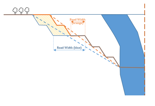
If we want to use really big equipment, then we’ll have to change the design parameters of our mine. Larger equipment requires sufficient space to operate. For example, if we’re talking about a larger truck, the haul roads will need to be wider, and we’ll need a better road bed and bearing surface, i.e., a more expensive haul road that will remain stable under the heavier truck weight. Wider roads in a pit will necessitate a higher stripping ratio, since the pit walls will be pushed back to the waste area, and this will increase the mine development costs.
Consider this figure in which we have an orebody shown in blue and two different pit limits for two different roadway widths. The blue pit limit corresponds to a wider road than the orange pit limit. As you can see in the below figure, the blue pit needs additional waste removal equal to the dashed area, compared to the orange pit. Therefore, more waste is now mined out per ton of ore, and the stripping ratio will be higher.
Loss of Selectivity
We talked earlier in the course about selectivity, and you will recall that selectivity is a measure of how effectively we can extract the ore of interest while taking as little waste material as possible. Larger mining trucks need to be matched with larger loading equipment; and larger loading machines have larger buckets. A large bucket reduces selectivity in loading, and that means you will dilute more of the ore with waste material than with a smaller piece of loading equipment.
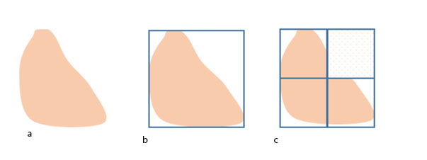
This effect can be illustrated by considering the block of ore shown here, in Figure 7.1.3(a), assume that we have two options to load the material: a large bucket shown by the blue outline in Figure b and a small bucket the size of the blue outline in Figure c. With the large bucket, we will load all of the ore in the block, shown in orange, as well as the waste material shown in white. With the small bucket, we can be more selective, and taking three small bucket loads we get all of the ore with far less waste. As you can see, the option with the small bucket will reduce the dilution, and this in turn will reduce the unit cost of production.
Equipment Life Cycle
The service life of mining equipment is measured in tons, hours, or years, depending on the type of equipment. A haul truck might have a life of 100,000 hours of operation, which may translate into 15 years of service life at a particular mine, and maybe as much as 20 years at a different mine with a different work schedule. Given the high capital cost of mining equipment, much effort is given to match the life of equipment with logical periods of production at the mine. This is yet another reason why mine planning is so important, to ensure that maximum benefit can be obtained from every piece of equipment over the life of the mine.
It is vital for a mining operation to determine an operationally viable mining sequence for the deposit and, subsequently, a production schedule that is achievable and economically sound. The Mine Planner's objective is to schedule and plan operations to achieve maximum return (of profit) on investment, through capital investment (e.g., mobile equipment), mine design, production scheduling, and preparation of the mineral product according to specifications that are required for the market. Therefore, “quantity” and “quality” would be important “drivers” in mine production planning.
BEFORE MOVING ON TO THE NEXT LESSON, please take a little time to think about the concepts presented in this section of this lesson. These will be underlying themes in many other topics.
7.1.2: Mathieson's Planning Objectives
7.1.2: Mathieson's Planning Objectives
We’ve talked about the economic foundation of mine planning, and we’ve looked at several examples of how the mine design and the mine schedule can affect the economics. This is a good foundation for understanding the material in this course, as well as preparing you for more detailed studies in later courses. I want to conclude this lesson on mine planning by presenting a list of objectives to guide your mine planning decisions.
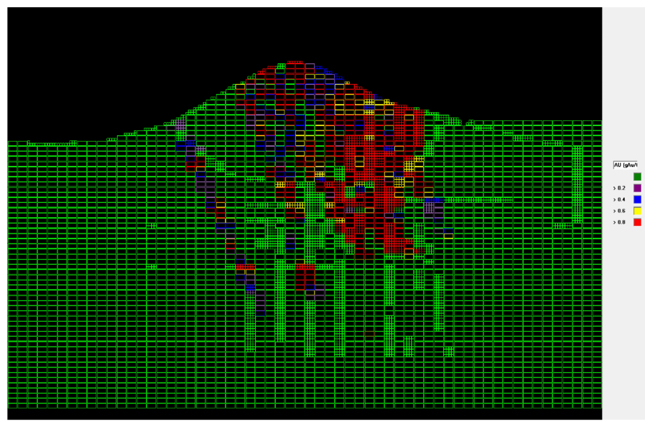
The starting point for your mine planning activities will be the geological model of your orebody; and this will be true, regardless of whether you have come into the planning process at the startup of the new mine, or after the mine has been in operation for years. You will have a block model, which details the grade of the ore in discrete categories and locations. The size of the blocks and the number of categories is a separate decision, but one that does not need to be addressed here. Consider this block model, which uses one of five grade ranges for each block. So, this is your starting point – where do you go from here? Undoubtedly, your approach will be multifaceted. There is a set of planning objectives first compiled by Mathieson and published in 1982. These objectives apply more or less to underground as well as surface mining, although his famous paper was directed at the surface mining community.
Here is a list of the major objectives of any surface mine planning exercise at the feasibility level:
Mining the “Next Best” ore
Mine orebody in such a way that for each year the production cost to produce a given amount of final product is minimized. What do we mean with the “Next Best”? The next best ore block here is the block that (i) maximizes the profit and (ii) does not contradict any other constraint or limitation, e.g., equipment operating room and slope design. To find the “next best” in the above figure, we will look for the red blocks that are close to the surface. We chase the red blocks because they contain a higher grade of ore that is easiest to mine. What do I mean by easiest to mine? I mean minimizing the production costs, and this normally suggests closest to the surface without any complicating factors. A complicating factor would be an environmental constraint or a geologic anomaly, for example.
Maintain sufficient ore exposure
Give yourself options on which mining face or faces will be scheduled for production on a given shift. If you normally have five active faces on any given shift, then you will want to have at least ten faces available for work on any given shift. Then, if there are unexpected ground control or other problems, you can simply move active work to a different face. Moreover, mining operations try to maintain enough ore exposure to meet production needs for an extended period, e.g., six months. This helps the company to reduce the risk that unforeseen events will adversely impact production. This is particularly true in the early years that are so critical to economic success. Unforeseen events could include a shortage in the equipment fleet due to delivery delays or significant breakdowns, labor issues due to union strikes, or difficulty in recruiting and retaining certain positions, adverse weather events, slope stability issues, and so on. Don’t forget to account for geological and engineering miscalculations. In the early stages of mine planning, geologic and operational information is limited, and this creates a greater level of uncertainty.
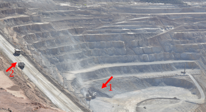
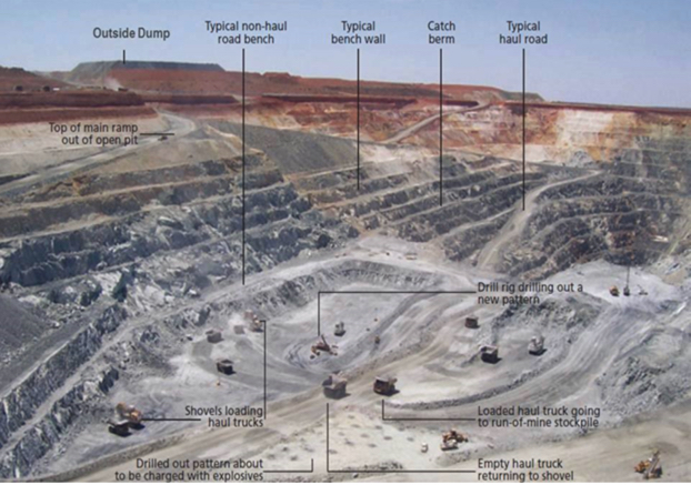
Maintain proper operational parameters
Adequate bench width and properly designed haul roads are essential to achieving the design level of production. Limited operating space on the bench can increase the cycle time of the operation, which will decrease productivity and production, and it may pose a safety hazard for the equipment and workers. Improperly designed haul roads can: increase the round-trip cycle time, which will affect productivity and production; greatly increase tire wear, and tire replacement represents a major cost element in many surface operations; and create safety hazards.
Let’s take a look at this picture of an open-pit copper mine. A loading and hauling operation is identified with arrow #1. If there were not enough operating room for the shovel, it would take longer for the shovel to dig, load, and dump the material. Concurrently, the truck driver will likely require more time to maneuver into position for loading. Arrow #2 points to a loaded truck traveling uphill to the dumping point and an empty truck making the return trip down-hill to the loading point. If proper operating room is not maintained, the trucks will need to reduce speed when passing. More importantly, there may be an increased risk for a truck to lose control and then go over the edge or crash into another truck. Therefore, it is incumbent on the mining engineer to design properly the benches and haul roads to ensure that safety and production are not compromised.
Defer stripping
As we discussed before, we would like to expedite profit making in the early years of operation, and to the extent that it is logical and achievable, we want to minimize the amount of stripping required to access the orebody. In the process of deferring stripping, we don’t want to compromise other objectives, such as the two that we just discussed.
Minimize the risk of delays in the initial cash flow
The production rate that is used for the early years of the mine is one of the more critical variables in determining the initial cash flow. Yet, it is also the variable that is subject to significant change over which you may have little control. Equipment delivery, outside contractor performance, workforce startup and training issues, and initial geologic uncertainty are examples of factors that can halve your production target in a given year. Imagine if your financial projections as supported by mine planning missed their target by 50%! Once again, you’d be looking for a new job! Consequently, the first year or two of production is de-rated to account for these uncertainties. If you were designing the mine to produce 6 million tons per year, it would not be unreasonable to choose a target for two million for the first year and three million for the second year. These aren’t arbitrarily chosen but will be based on simulations and risk analysis. The point here is that it is important to determine achievable production levels in the first few years of the mine life.
Maximize pit slope, while minimizing the risk of slope failure
We’ve looked at a few examples to illustrate the effect of the ultimate pit slope on stripping ratios and economics; and the “take-away message” is that the steeper the slope, the more favorable the economics! Unless, of course, you have slope failure! And then, once again, you are looking for a new job! Just kidding ... Even with very good ground control, slope failure can occur. It’s like walking a tight rope. The slope stability calculations are limited by geologic uncertainty, and so, safety factors are required. But how much of a safety factor: 1.5, 2.0, 4.0, or 10? There are analytical methods in rock and soil mechanics to improve the accuracy of your predictions, and the use of risk analysis is standard. Nonetheless, the possibility of a slope failure weighs on the operations and engineering personnel. A clever and necessary approach is to choose a smaller safety factor, but utilize sophisticated slope monitoring instrumentation and techniques to detect the earliest signs of incipient slope failure. Engineering and operational interventions can be initiated immediately to prevent a catastrophic loss.
Optimize cutoff grade and production rate
Mining companies perform market surveys to make an accurate estimation of the amount of product that can be sold every year, and at what price. Remember, the cutoff grade was based on an assumed selling price and an assumed mining cost. As the market changes, the cutoff grade will change, and as production costs change, for better or worse, the cutoff grade will change.
As an example, the annual tonnage that can be sold is suggested by the marketing surveys for a copper mining operation. The annual production rates for the mill and mine are calculated accordingly. Keep in mind that mill production rate only depends on ore, whereas the mine production rate includes both ore and overburden removal. The mining equipment should be selected in such a way that sufficient ore is sent to the mill, and so, there is sufficient capacity to maintain additional faces to satisfy the “sufficient exposure” constraint. There are flexibilities for both ore production and waste mining plans. Moreover, multiple destinations may be considered for the material, including sending material to a waste dump, a low-grade leach dump, a high-grade leach dump, the mill and sometimes an ore stockpile, which is used to feed the mill when mine production is down. Cutoff grades need to be determined for each of these destinations. I imagine that you are beginning to appreciate the need for thorough mine planning to support these decisions — hence, this objective to examine the economic merits of alternative production scenarios, including different ore production rates and cutoff grades, for the purpose of optimizing the cutoff grades and production rates.
Optimize method and equipment selection
Earlier in this module, the importance of selecting the proper size of mining equipment was discussed. We learned that all of the possible options for the fleet should be studied and the best option should be selected. Mining equipment selection is a complex multi-criteria decision-making problem. These parameters include, but are not limited to, the unit cost of the operation, equipment availability, selectivity, operating space, environmental impact, and many other technical and economic parameters. A mine planner should subject the proposed mining strategy, mine development plans, equipment selection, and environmental protection plans to very thorough "what if" contingency planning.
This is also a good time to remind you that mining methods and equipment can evolve and change over the life of a mine. Just because you started out with a specific method and unit operations, does not mean that you have to stick with those for the next 30 years! You may want to change one or both based on new conditions, new technology, and so on. This can only be assessed through ongoing engineering simulations and analyses.
This concludes the summary of mine planning objectives as first outlined by Mathieson. While these eight objectives are timeless in their guidance, i.e., they were true 30 years ago and will be every bit as true 30 years from today, we need to add one additional objective to reflect society’s nascent and evolving value of sustainability.
Develop sustainable mine plans to achieve sustainable mining operations
We talked about sustainability in mining and its importance. If we are to mine in a sustainable manner, then our mine planning must reflect that value. This means taking steps to avoid sterilizing the reserve, maximizing recovery rates, minimizing environmental impact, and ensuring worker safety and health through the design of the mine, the selection of equipment, and the choice of unit and auxiliary operations. Much, but not all of the mining industry has been the vanguard of the triple-bottom line: economic, safe, and environmentally responsible operations. The triple bottom line concept has evolved and changed into the term sustainable operations. It will be your responsibility through mine planning to ensure that the industry continues its journey to sustainable mining in all commodities and in all locations.
Now, armed with an understanding of mine planning, let’s take a look at surface mining methods!
Lesson 7.2: Mechanical Surface Mining Methods - Introduction & Open Pit Mining
Lesson 7.2: Mechanical Surface Mining Methods - Introduction & Open Pit Mining
Earlier in the course, we discussed the factors that go into the selection of a mining method, and we listed the major mining methods. Why can’t we use a single method to extract all minerals located near the surface?
Consider the following examples:
- A flat-lying bituminous coal seam of relatively uniform thickness. The coal is soft and the overburden can range from soft to moderately hard.
- A steeply pitching anthracite coal seam of relatively uniform thickness. The coal is moderately soft and the overburden can range from soft to moderately hard.
- A massive porphyry copper deposit shaped like a bowl or a giant mushroom. The orebody and surrounding rock are generally hard, i.e., strong and competent.
- A placer gold deposit, which consists of unconsolidated banks or layers of discrete grains, which are often found in rivers or streams.
Hopefully, thinking about these has triggered your memory of our previous lessons. The primary factors affecting the choice of a surface method are the spatial orientation of the orebody with respect to the surface, i.e., tabular or amorphous, and steeply dipping or flat-lying; geotechnical characteristics or the orebody and the surrounding materials, i.e., consolidated or unconsolidated, and strong or weak; and the topography, i.e., relatively flat, hilly, or mountainous. The size of the orebody and the production requirements may affect the choice of a method or the sub method, and as we discussed earlier in the semester, there are several secondary factors that could come into play. These will become more apparent as we look at the different methods.
Surface mining methods can be categorized into two broad groups based on the method of extraction:
- Mechanical Extraction Methods
- Aqueous Extraction Methods
Mechanical extraction methods employ mechanical processes in a relatively dry environment to mine minerals from the Earth’s crust. In contrast, aqueous methods involve water, or occasionally other liquids, to extract minerals.
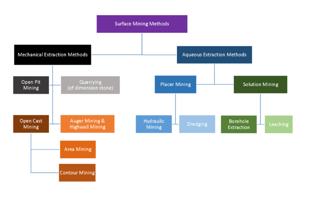
The surface mining methods can be classified as shown here. We will discuss the mechanical extraction methods in this lesson.
Click to expand to provide more information
Surface Mining methods can be divided into two broad categories:
- Mechanical Extraction Methods, and
- Aqueous Extraction Methods.
Aqueous Extraction Methods involve water, or occasionally other liquids, to extract minerals.
Mechanical Extraction Methods, which are discussed in this module, include:
- Open Pit Mining,
- Quarrying (of dimension stone),
- Open Cast Mining, which includes Area Mining and Contour Mining, and
- Auger Mining and Highwall Mining.
OK, with this brief “memory jogger” out of the way, let’s start our discussion of mechanical extraction methods with one of the most frequently used methods, known as open pit mining.
7.2.1: Open Pit Mining
7.2.1: Open Pit Mining
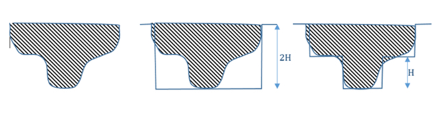
Open pit mining almost always applies to non-coal materials, mostly metal and aggregate mining. However, near-surface steeply dipping coal seams are extracted using open pit mining. Reclamation, i.e., returning the land to an acceptable standard of productive use of the open pit mine is deferred until the mine closes. Let’s look a few diagrams to better understand the relationship between the suitability of open pit mining and the spatial characteristics of the deposit.
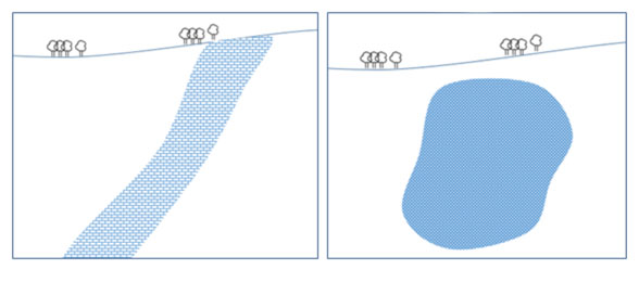
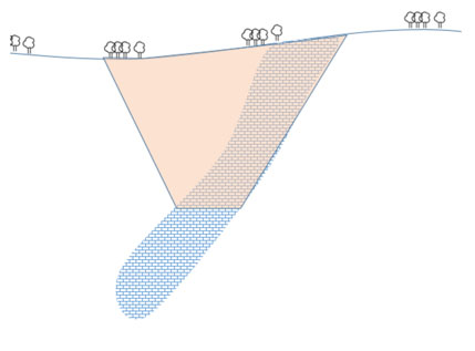
On the right side, you can see a massive deposit, and on the left, there is a steeply pitching deposit.
Now, try to imagine the way that mining should proceed to extract the ore in each case. You may think of the “open pit” as a huge upside down cone that is superimposed onto each deposit. In the case of the deposit on the right side, we would have this.
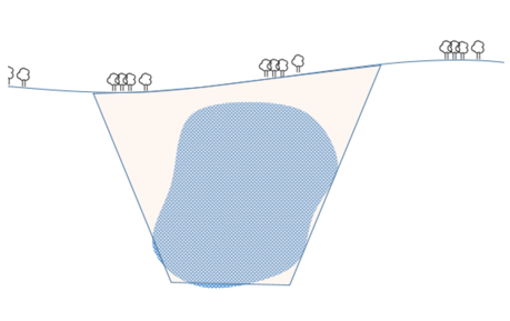
In the case of the steeply dipping deposit on the left, our open pit would look more like this.
These diagrams also provide insight on the reason that reclamation has to be delayed until the end of the mine life. Simply put: we start mining from the surface and work our way, level by level, down into the deposit. If we were to return the waste material to the place where we mined it, we would block access to the ore in the lower levels.
Did you notice in the diagram of the steeply pitching deposit, the pit bottom stopped well before reaching the end of the orebody? As we go deeper, our stripping ratio will eventually become prohibitively large. Moreover, as we go deeper, mining costs, other than stripping, will increase also. For example, the time and cost to transport ore from the lower levels of the pit to the processing plant will increase to the point at which we will have to buy additional trucks to maintain production levels. When we reach the point where the cost to recover the ore exceeds its value, we have two major choices: begin the mine closure stage of the mine’s life; or begin an underground mining operation. The latter is common in metalliferous deposits. Of course, that point may not be reached for decades, as the depth of the pit may exceed 2000’ in some cases.
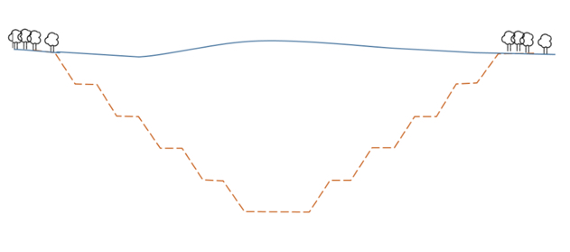
In the previous diagrams, I illustrated the sides of the pit with a straight line. Open pits cannot be operated in this way. Instead, the pit walls need to step down, which provides access to the pit by people and equipment, and it provides a working platform at each level. We refer to these steps as benches, and this diagram is a more accurate representation of the pit than are the previous ones.
The number of benches will depend on the bench height and the ultimate pit depth. In the last lesson, the concept of slope stability was introduced, and that will weigh heavily in the decision of the number of benches, their dimensions, and the angle of the pit wall. It is incumbent on the mining engineers to ensure sure that slope instabilities will not occur throughout the mine life, as we discussed in the last lesson.
7.2.2: The World's Largest Single Pit
7.2.2: The World's Largest Single Pit
Here is an aerial view of one of the largest and most famous open pit copper mines – the Bingham Canyon Mine operated by Rio Tinto.
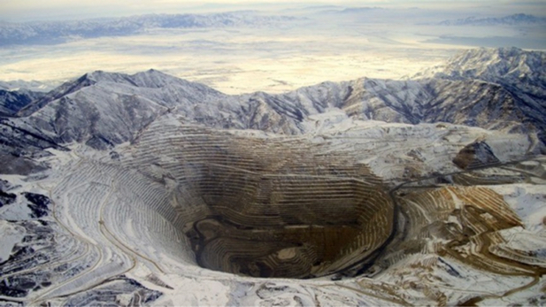
Rio Tinto Kennecott runs the world’s largest single pit, Bingham Canyon open pit copper mine. This pit stretches three-quarters of a mile deep and nearly three miles across at the top. The pit is wide enough to stack 12 aircraft careers end-to-end. This mine carries out a sequence of drilling, blasting, loading, hauling, crushing and conveying 24 hours a day, seven days a week, 52 weeks a year. It has been in production for more than a century, and has produced more than 19 million tons of copper. Gold, silver, molybdenum and sulfuric acid are byproducts of Bingham Canyon Mine. The mine has 12 shovels (10 electric, two hydraulic) that fill an average of 2,100 haul-truck loads each day. There are 110 haul trucks ranging in capacity from 240 to 320-tons. You might not expect this, but there are seven water trucks with 50,000-gallon tanks, and these trucks spray water onto haul roads round-the-clock to reduce dust. Ore is transported to, and unloaded into, one of the world’s largest crushers, running at a rate of 10,000 tons per hour. At the end of this lesson, I am going to direct you to a video where you will learn more about these large open pit mines.
7.2.3: Pit Terminology
7.2.3: Pit Terminology
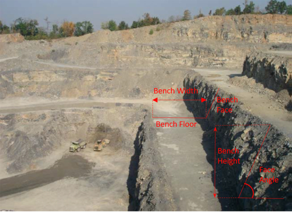
Now, let’s learn the terminology associated with the pits. Using this figure, we can define key elements.
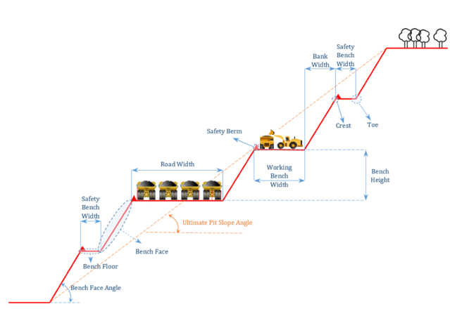
- Bench floor: Horizontal surface of the bench
- Bench face: Vertical surface of the bench
- Face angle (α): The average angle the face makes with the horizontal
- Bench height (H): Vertical distance between upper and lower bench surface
- Toe: Interior vertex formed by the intersection of the bench face and bench floor
- Crest: Exterior vertex formed by the intersection of the bench floor and bench face
- Bench width: The distance between the crest and the toe measured along the upper surface
- Bank width: The horizontal projection of the bench face
There are two types of benches in each open pit mine: working benches and safety (catch) benches.
Working Benches
Working benches are where unit operations (drilling, blasting, loading, and hauling) are performed. Working benches are wider than safety benches to provide enough room for the mining equipment to perform their tasks.
Safety (Catch) Benches
Safety benches are designed to collect the sliding material from the benches above and stop the downward progress of large rock pieces or boulders.
Bench height
Bench height is one of the first parameters to be determined during the mine design process. Can you guess the parameters that should be taken into account when determining proper bench height?
Bench height depends on several parameters:
Overburden and Ore Properties
We discussed before that ultimate pit slope depends on material (ore and waste) properties. These properties include rock strength and the number and direction of rock discontinuities. Benches are just like smaller pit walls with a much lower height (usually 20 to 50 feet). Therefore, benches should also be designed in such a way that no risk of instability is created due to excessive height of benches. There is a direct relationship between rock strength and safe values for the bench face angle and bench height.
Production Rate
Production rate of a mine is a parameter that is usually determined by market demand and selling capacity. When the required production rate is determined based on the market situation, then the annual mine production rate that includes ore and waste extraction is determined in such a way that enough product for the sale purposes is guaranteed. Higher benches are normally required to achieve higher production rates.
Degree of Selectivity
We discussed selectivity in the last lesson, and the definition of the parameter is unchanged. However, insofar as bench height is concerned, there is a selectivity issue, which is illustrated with these three figures, below. These figures (are attempting to) illustrate local variations in grade, and the effect of different bench sizes on the selectivity.
As you can see, the smaller bench height results in better selectivity. Better selectivity means less waste is mined, loaded, hauled, and run through the mineral processing plant; and this translates into lowered mining and processing costs. These mineral beneficiation plants are designed to work best when the characteristics of the feedstock into the plant lie within a specified range. If your feed into the plant is outside of the range, the plant’s efficiency will suffer. You may not recover all of the mineral, for example. Operating mines will use a blending strategy, where on a truck-by-truck basis, they will blend higher-grade and lower-grade ores to achieve a feed that is within the specified range. The more selectivity you have, the more effectively you can blend.
Size and Type of Equipment to Meet the Production Requirements
After the annual production rate of the mine is determined, the required daily and even hourly production rates will be calculated based on assumptions about the number of working days per year and the number of shifts per day. Then mining equipment is selected so that these production requirements can be met. Loading equipment is usually the first to be selected; next, appropriately sized trucks are chosen to match with the loader, and then the complete fleet of loading and hauling equipment will be specified. The maximum reach of the loading equipment should be roughly the same as the bench height.
Regulatory Limits
Federal and state regulatory agencies have regulations that limit bench height for specific mining operations, depending on the commodity, to ensure the safety of mine workers and equipment inside the pit. The engineering calculations may indicate that a greater bench height is safe, but it is unlikely that the regulatory agency would allow an exception to their rule.
Bench Face Angle
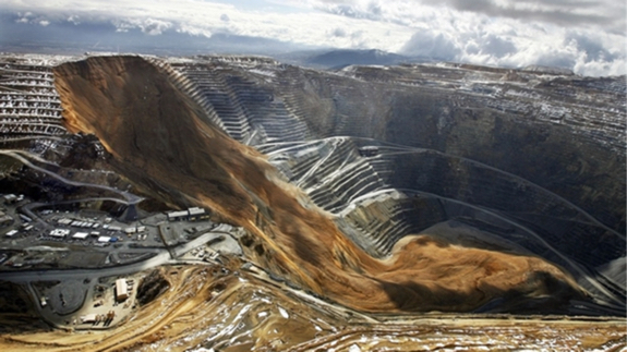
Bench face angle is ultimately limited by geotechnical considerations, as we generally want to have as steep of an angle as we can sustain without an unacceptable risk of a slope failure. Despite excellent engineering and slope monitoring, failures can occur. This photo was taken in 2013 shortly after the slope failure at the Bingham Canyon Mine. Look at the shops and warehouses in the picture to appreciate the size of this failure. It is truly a miracle that no one was killed – the potential was there for massive loss of equipment and multiple fatalities.
Please watch the following video (20:11). It will give you a good overview of the open pit mining method, as well as a bit more background on the slope failure. The first half of the video presents an interesting historical perspective, and the last half shows contemporary mining practices.
Safety Berm
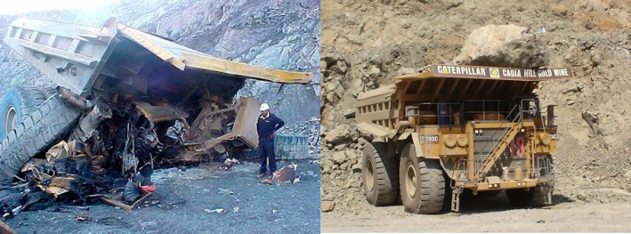
A safety berm is a pile of broken material constructed along the crest to form a “guard rail” to prevent trucks or other equipment from inadvertently driving over the edge of the haul road. It also serves to catch falling rocks. The height of the safety berm should be greater than or equal to the tire radius of the largest truck. These berms are required by federal regulation, but even with berms, accidents can happen. The picture on the left shows a haul truck, or what remains of it, after going over the highwall; and the one on the right shows a piece of rock that slid off the highwall and landed on a truck below. The former most certainly resulted in a fatality, whereas the latter probably did not, in this instance.
Haul Roads
These are added to the pit walls to provide access between benches and the plant next to the pit. Open pit haul roads have a gradient up to 15%. The width of the haul road is designed based on the width of the largest truck that travels in the pit and the number of the lanes that are required to provide proper access for haul trucks, auxiliary equipment such as explosives trucks and water trucks, and smaller vehicles, such as pickup trucks, while minimizing congestion.
Now, let’s review the bench geometry concepts and open pit elements by looking at two annotated photographs.
7.2.4: Mines in the U.S.
7.2.4: Mines in the U.S.
Here is a list of the largest open pit mines in the U.S.
| Mining Operation, State | Operator | Commodity | Mining Method |
|---|---|---|---|
| Nevada, NV | Newmont Mining Corp. | Gold | Open Pit and Underground |
| Morenci, AZ | Freeport-McMoRan Copper & Gold Inc. | Copper-molybdenum | Open Pit |
| Cortez, NV | Barrick Gold Corp. | Gold | Open Pit |
| Goldstrike, NV | Barrick Gold Corp. | Gold | Open Pit and Underground |
| Bagdad, AZ | Freeport-McMoRan Copper & Gold Inc. | Copper-molybdenum | Open Pit |
| Bald Mountain, NV | Barrick Gold Corp. | Gold | Open Pit |
| Safford, AZ | Freeport-McMoRan Copper & Gold Inc. | Copper-molybdenum | Open Pit |
| Mission Complex, AZ | ASARCO LLC | Copper | Open Pit |
| Sierrita, AZ | Freeport-McMoRan Copper & Gold Inc. | Copper-molybdenum | Open Pit |
| Minntac, MN | U.S. Steel Corp. | Iron ore | Open Pit |
| Chino, NM | Freeport-McMoRan Copper & Gold Inc. | Copper-molybdenum | Open Pit |
| Bingham Canyon, UT | Kennecott Utah Copper Corp. | Copper-molybdenum | Open Pit |
| Ray, AZ | ASARCO LLC | Copper | Open Pit |
| Hycroft, NV | Allied Nevada Gold Corp. | Gold | Open Pit |
| Hibbing Taconite, MN | Cliffs Natural Resources Inc. | Iron ore | Open Pit |
| Tyrone, NM | Freeport-McMoRan Copper & Gold Inc. | Copper | Open Pit |
| Tilden, MI | Cliffs Natural Resources Inc. | Iron ore | Open Pit |
| Marigold, NV | Goldcorp Inc. | Gold | Open Pit |
| Fort Knox, AK | Kinross Gold Corp. | Gold | Open Pit |
| Miami, AZ | Freeport-McMoRan Copper & Gold Inc. | Copper | Open Pit |
| Cresson, CO | AngloGold Ashanti Ltd. | Gold | Open Pit |
| Smoky Valley Common Operations, NV | Kinross Gold Corp. | Gold | Open Pit |
| Ruby Hill, NV | Barrick Gold Corp. | Gold | Open Pit |
| Keetwatic Taconite, MN | U.S. Steel Corp. | Iron ore | Open Pit |
| Mineral Park, AZ | Mercator Minerals Ltd. | Copper-molybdenum | Open Pit |
As you can see from this list, most of the US largest open pit mines in the U.S. are located in the state of Nevada and Arizona, where there are large deposits of gold and copper-molybdenum.
The sequence of steps for the development of an open pit mine is as follows:
- determining the three-dimensional distribution of mineralization and grade;
- establishing the economic limits for the pit;
- selecting suitable sites for waste embankments and soil stockpiles;
- clearing vegetation from the land intended as sites for pit and waste embankments;
- siting of processing, maintenance, office, and transport facilities close to the pit but outside potential pit limit expansion;
- selecting equipment; laying out haulage roads;
- initiating “pioneering” cuts in the form of “box cuts” or access roads.
Acquisition of rights, permitting, and construction of facilities are not shown separately in this list, but are an overall part of the development sequence.
Rio Tinto is a global mining company that owns the Kennecott Bingham Copper Mine, and they have produced an informative virtual tour (may be viewed at your own pace) of the mine and related operation. It is outstanding. You should watch it several times to reinforce the content of these lessons as well as to see vivid images of the equipment and operations in action. Follow the instructions below to get started.
- Go to the Kennecott homepage. [6]
- Scroll down until you see the Start Virtual Experience.
- You will be asked to provide your name and email address. You may do so if you choose, but if you don't want to do so, simply click the "X" in the upper right corner of the dialog box.
7.2.5: Stone for Construction, Chemical, and Other Uses
7.2.5: Stone for Construction, Chemical, and Other Uses
Before leaving this lesson on open pit mining, I want to mention an important application of this method – stone for construction, chemical, and other uses. You’ll recall from our initial discussion on mining methods that I told you that the common term for this mining is quarrying, not open pit mining. As mining engineers, that does not thrill us because quarrying is the correct term for the mining of dimension stone. However, it doesn’t much matter what we think, because millions of people use the word quarry and quarrying to refer to these open pit operations where stone is mined. Frankly, I suggest that you surrender, and refer to them as quarries as well! That’s what I am going to do here!
If you recall the graphic at the beginning of Lesson 7.1 [7] in this module on surface mining, these stone quarries account for more than a third of all mines in the U.S., numbering over 6000! The majority of the stone that is mined is crushed and used for construction – roadbed, concrete, bituminous concrete, erosion control, and so on. Limestone and sandstone are typically mined, but in some areas, an igneous rock known as trap rock is mined. These construction uses are relatively low value with the product selling for around $10 per ton. A small but important market exists for chemical grade limestone, manufactured sand, and specialty products such as kitty litter or the small grains incorporated into the surface of roof shingles. These markets will pay upwards of hundreds of dollars per ton for the mined product. Given the importance and size of the quarry industry, I wanted to make a few additional comments on this application of open pit mining.
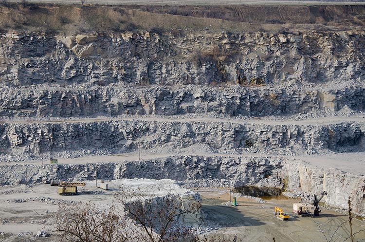
Everything that we have discussed under the topic of open pit mining applies to quarries, i.e., open pits in which crushed stone is mined. The planning, engineering, equipment, and so on, are the same. Most quarries are smaller than the large open pit mines for recovering metals, and as such, the equipment selection may be different. Wheeled loaders are more likely to be used than shovels, and the haul truck capacity will be smaller. Hydraulic excavators may be used, but it would be rare to find a shovel. The safety, health, and environmental challenges are similar, and the engineering design and production engineering is similar. Looking at this quarry, for example, it would be difficult to distinguish it from any other open pit mine.
If you take MNG 441, you will learn more about the design of these open pits. Also, we offer an elective course focusing on aggregates with an emphasis on stone quarries.
Lesson 7.3: Mechanical Surface Mining Methods - Open Cast Mining & Related Methods
Lesson 7.3: Mechanical Surface Mining Methods - Open Cast Mining & Related Methods
Open Cast Mining
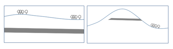
Open cast mining is usually associated with coal or other tabular deposits that are more or less flat-lying. A significant difference between open pit and open cast mining methods is that in open cast mining, overburden that is removed to gain access to the ore is immediately placed in the previously mined cut. Therefore, reclamation occurs concurrently with other mining activities.Two major sub-methods within open cast mining are area mining and contour mining. If the topography is relatively flat as illustrated in the left figure, then area mining is appropriate. If the terrain is hilly or mountainous as indicated by the figure on the right, then contour mining is indicated.
The reason that different methods need to be used depending on the terrain will become clearer as we look at them in more detail. Area mining is able to use much larger equipment, and as such will generally have lower stripping and mining costs. However, this large equipment requires a flat-lying topography to operate. Contour mining, on the other hand, is well suited to mining around the mountainsides, but uses smaller and different equipment; and, accordingly, we lose an economy of scale that we have with area mining. Nonetheless, it is an important and viable method to recover coal deposits. Let’s take a look at each sub-method in more detail.
Required Activities
Read There is no reading for this section
Complete Quiz 7 on Lessons 3, 4, and 5
7.3.1: Area Mining
7.3.1: Area Mining
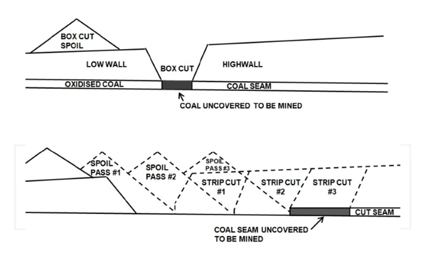
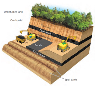
In the left figure, we have relatively constant thicknesses for both overburden and ore. Our first step is to remove the surface vegetation and stockpile the topsoil for later use in reclamation. We will only remove the vegetation and topsoil in the area that we will mine within a period of weeks. Next, we need to gain our initial access to the seam, and we will do this with a box cut. Depending on the hardness and tightness of the overburden, we may need to drill and blast to facilitate its removal. If it is soft enough, we’ll remove it without the need to drill and blast. Depending on the thickness of the overburden, and the required size of the box cut, we will probably use a dragline to make the box cut, although it could be done in certain cases with dozers and scrapers. The overburden from the box cut will be placed to the side of the pit. When the coal seam under the box cut is exposed, we start mining the coal. After the coal in the box cut is removed, a subsequent cut is accomplished and the waste material from the second cut is placed in the space created by the initial box cut. This process continues by making subsequent cuts, putting extracted overburden in the former cut and mining the uncovered coal seam. The collection of sequential cuts forms a strip, and the strips will traverse a portion of the property. Take a look at this figure, and don’t be concerned about the difference between the low wall and the highwall. You can see the box cut. In the lower part of the figure, you can see the strips being mined and the overburden or spoil placed into the adjacent and previously mined strip. The overburden swells in volume when it is extracted, and that’s why you see the piles of spoil protruding above the original contour of the land.
Sometimes, it is difficult to imagine the cuts and strips and how it all progresses. As you look at the pictures and diagrams in this lesson, it will come together for you. Another visual for right now would be to think of a bowling alley with its many bowling lanes. You can think of the bowling alley as the area to be mined, and each lane as a strip. Within each strip, a series of cuts will be made so that the “mining activity” can progress from the beginning to the end of the strip. Mining of the first strip is a little tricky, but once it has been completed then all of the other strips will be completed as shown in the diagram above – remove the overburden, expose the coal seam, mine the coal, cast the overburden from the next cut into the previously mine strip.
Overburden removal in US area mining is commonly accomplished with large draglines, stripping shovels, or in small mines, by conventional excavation and haulage (truck-shovel or dozer-scraper) methods. In some other countries such as Germany, bucket wheel excavators are also used to remove overburden. Dozers and scrapers are also used in clearing vegetation, removing topsoil and subsoil, establishing level benches and surfaces for the dragline, as well as many other activities that involve pushing the spoil. In the next lesson, we’ll look at a video of area mining to recover phosphate, and you will see the prep work done by the dozers as well as the operation of the dragline.
Here is a picture of a Black Thunder Mine. You can see the individual strips where overburden has been placed; and within each strip, note the individual piles. Each pile corresponds to a cut. The uncovered, but unmined coal seam is visible as well. Given the thickness of this seam, on the order of 100’, a large shovel will be used to mine it. If it were thinner, say 10’, then a small shovel could be used, but more likely a wheeled loader. Often, the coal seam is drilled and blasted to facilitate rapid loading of the coal.
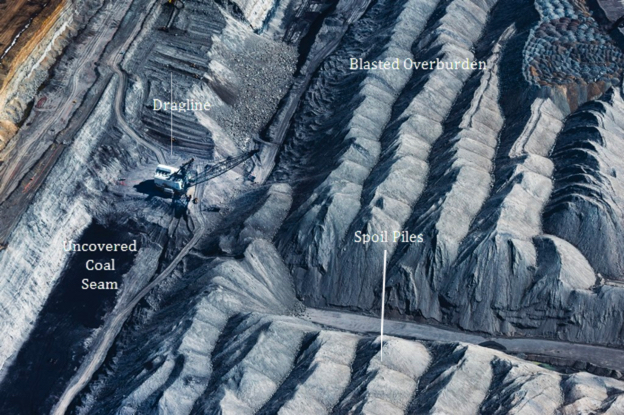
There are a few other elements within this picture that I’d like you to note. Do you see the blasted overburden, and where is the dragline sitting with respect to the top surface of the blasted overburden? Quite a bit lower, right? So, how does this happen?
A dragline has a limited reach, and there is a tradeoff between its reach and the size of the bucket. For example, it may have a reach of 200’ with a 200 yd3 bucket, and 300’ with a 120 yd3 bucket. Without getting into the design details, optimizing the reach and bucket size combination sometimes requires that the overburden be removed in two separate passes. The interesting thing about the process in the Powder River Basin is that they remove up to 40% of the overburden by a process known as cast blasting. In cast blasting, not only does the blast loosen the overburden, but the round is designed such that up to 40% of the overburden is actually thrown or cast into the adjacent strip! They may use a million pounds of ANFO or more to accomplish this!
Dozers are then used to push more of the overburden into the adjacent cut, and importantly, to create a flat and level surface for the dragline to operate. You can also see a temporary haul road developed by the dozers to provide access to the coal seam for haul trucks and to the dragline pad for smaller vehicles to service and supply the dragline.
I want to point out one last detail before leaving this picture. Did you notice the shape of the pile of overburden? They are all very distinct and nearly identical in shape. Do you think that is a coincidence? The piles of material form at an angle known as the angle of repose. This is the angle that a dry, granular, material in a very loose condition will form with respect to the horizontal. The angle of repose is a unique characteristic of the material, whether it is iron ore, coal, #2B crushed stone, flour, or sugar. If we know this angle, we can calculate all sorts of interesting things, such as the maximum angle of a conveyor belt so that the ore will not tumble back on itself or the size of a stock pile.
When it is time to reclaim the strip, bulldozers and scrapers work together to spread these spoil piles. Then the subsoil and top soil are placed back to reclaim and return the land to its original contour lines. Often, the rock layers immediately above the coal seam will be “acid bearing”, i.e., minerals such as pyrites that will create an acidic drainage when ground water percolates through those layers. Acid mine drainage is a great environmental concern, and to reduce the level of acidity under the reclaimed lands, crushed limestone is sometimes added to neutralize acid bearing layers. This process is called liming.
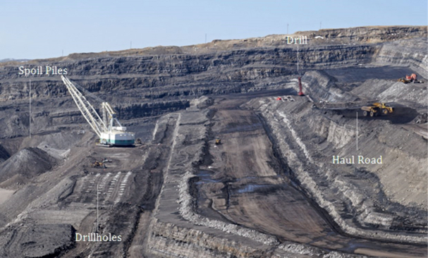
Here is another picture to illustrate the operations of the open cast area mining method.
Draglines
The dragline is an important piece of mining equipment, and you will find it in a variety of, and sometimes unexpected, operations. Let’s look at the fundamental parameters that define draglines for a given application. Each dragline is defined on two parameters: bucket capacity and boom length. Bucket capacity is used to determine the hourly production rate of the equipment, while the dragline’s dumping height and digging depth depend on its boom length. Digging depth, dumping height, and operating radius are the primary parameters that should be considered in selecting appropriate bench dimensions for a particular dragline. These three primary parameters are illustrated in this diagram.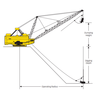
Please take a minute and think about the way that each of these three parameters plays a role in the design and the width of the strips.
Next let’s take a look at the key components of a dragline. You should understand the purpose of the drag, hoist, and dump ropes. You may want to think about the challenges of the structural design of the boom itself, and the tradeoff between bucket capacity and boom length. What about moving the dragline? How does it move about the bench? Very slowly and with great difficulty!!! There are no wheels nor crawler tracks because it is so massive and so heavy that conventional approaches would fail in all but the smallest draglines. Instead, the dragline walks! It sits on a giant cast iron tub so that its enormous weight can be distributed over a large area. On either side of the tub, there is a massive shoe. The shoe is connected to an eccentric cam, and to move, the shoes lift the tub off the bench and propel it forward where it comes to rest. And then, the cycle is repeated. Fortunately, the dragline does not need to move quickly in the course of normal production. However, if you need to move the dragline some distance, say to an adjacent property located on the other side of a highway, it can be a tedious process – like watching grass grow!
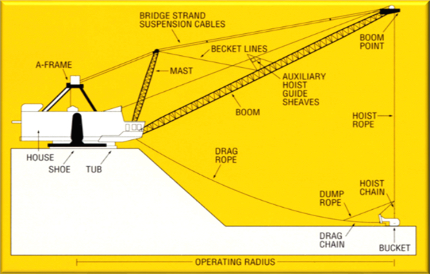
Now, let’s look at the operating cycle of the dragline in more detail, with the help of these diagrams.
The dragline is positioned on top of the blasted material, which has been leveled and prepared by a dozer. The drag bucket is positioned at its furthest reach, lying on the overburden. The drag rope will begin to pull the bucket towards the tub, and as the drag bucket is pulled, it will dig into the material and the bucket will be filled. Once filled, the dragline operator will begin to hoist the bucket and will begin to swing the boom toward the spoil pile. By the time the bucket reaches the spoil pile, the operator will have completed hoisting the bucket, and will then dump the bucket. Once dumped, the operator will swing back to the position to dig, while at the same time, dropping the drag bucket so that when the swing cycle has been completed, the drag bucket will be lying in position to begin the cycle all over again. A typical time to complete one cycle is 45 seconds.
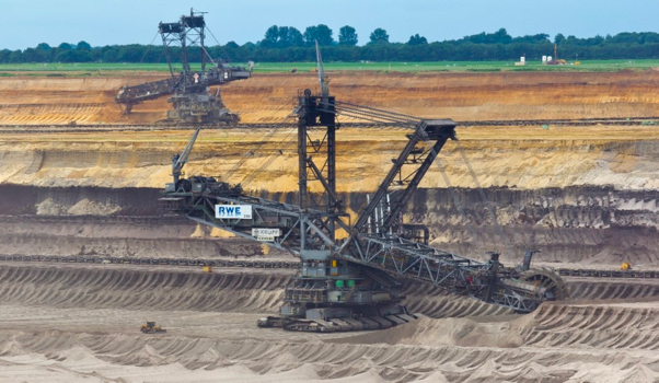
Bucket Wheel Excavators (BWEs)
Let’s close out this discussion on area mining with a brief mention of bucket wheel excavators (BWE), shown in the picture here. BWEs are massive machines to quickly remove overburden. To gain an appreciation for their size, look for the front-end loader in the lower left part of the picture. Did you find it? These machines have been used successfully in the brown coal fields of Germany for many decades. Some BWEs were imported into the U.S nearly 50 years ago. Unfortunately, the results were disappointing. The characteristics of the overburden were unsuited to the capabilities of BWEs. The bucket wheel excavator is best used for soft and loose overburdens. While these were common in the German lignite fields, they were less common here in the U.S. Consequently, they were never adopted for use in the U.S.
7.3.2: Contour Mining
7.3.2: Contour Mining
It would be great if all coal were found in conditions similar to those in the Powder River Basin: relatively flat and wide-open space, thick coal seams, and shallow cover (overburden). Mother Nature was not so accommodating! A lot of high quality thermal and metallurgical coal is found in rugged terrain, in areas such as the Appalachian Coal Field, which runs from Pennsylvania down to Alabama. Contour mining methods evolved to allow the economic extraction of coal using smaller and more agile equipment with more flexible mining patterns.
As with area mining, it is necessary to remove the vegetation and remove the overburden to gain access to the coal seam. There are two ways to handle the removed overburden: haul it all the way down the hill and put it into a chosen valley in horizontal layers; or to place it in the void of the cut, where the coal has been already removed. Mining will proceed by advancing into the hillside until reaching the break-even stripping ratio. At this point, the highwall will remain. Under certain conditions, we may choose to take advantage of the exposed coal seam, and develop an underground mine or practice highwall mining, which will be discussed later in this lesson.
Now, let’s take a look at a schematic view of contour mining approach and then a photo of a contour mining site. The diagram shows more than one coal seam. In fact, it is not uncommon for multiple seams to be recovered. It creates a small sequencing and scheduling challenge because you have to remove the interburden between the seams, and place it, but it is commonly done.
Note the highwall in the photo, and the exposed coal seam.
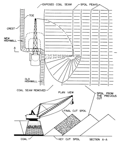
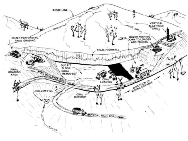
Haulback Mining
An important submethod within contour mining is haulback mining. Haulback mining, which is illustrated nicely in this diagram from the textbook, is a method in which overburden removal and then coal extraction follows the outcrop, proceeding in a series of nearly rectangular pits. As mining is advancing at one end of the rectangular cut, reclamation is occurring on the back end. In this method, mining roughly follows the contours of the land, and the ultimate pit width is dictated by the economic stripping ratio and steepness of topography.
Haulback mining starts with developing a box cut and hauling the overburden to a suitable disposal site. Coal is mined out and mining progresses with removing the next cut of overburden, and hauling it by truck, scraper, or conveyor to fill previously mined-out cut. This method is called haulback mining, because waste moves in a direction opposite to the direction of mining, as illustrated in the diagram.
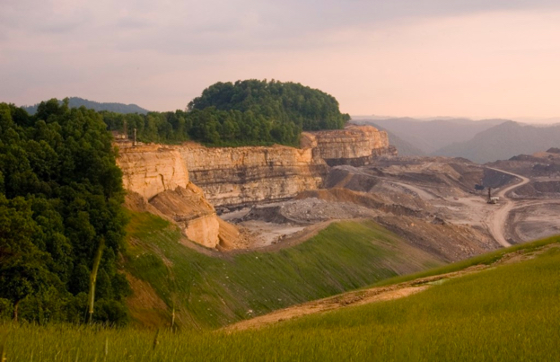
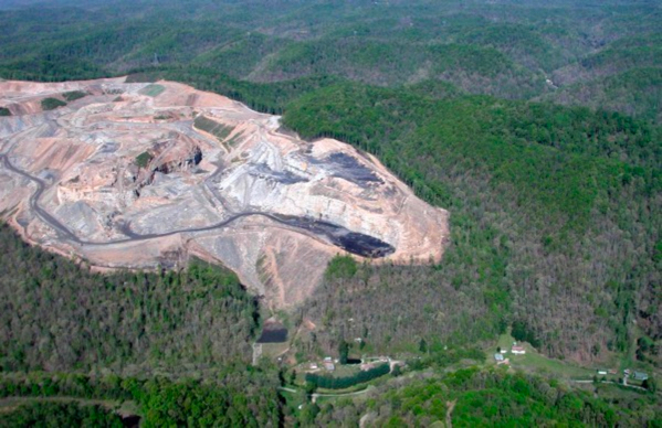
Mountaintop Removal
Mountaintop removal is another submethod of contour mining where a flat lying coal seam occurs near a mountain top and outcrops on opposite sides of a hill. When the overburden is sufficiently thin (less than 165 feet) across the hill, the deposit can be mined from outcrop to outcrop. In this method the hill is completely removed and the spoil is leveled rather than contoured to approximate the original topography, creating a flat land. This method was commonly used in Appalachia, but is very controversial, and is no longer recommended. The below picture shows a mountaintop removal operation in southern WV, prior to reclamation of the site.
7.3.3: Auger Mining
7.3.3: Auger Mining
Earlier in this lesson, you saw the highwall that remains after the ultimate pit limit is reached in a contour mining operation. At that time, I pointed out the possibility of recovering the coal under the highwall, by either developing an underground mine or highwall mining. The former is rarely economically feasible today, but the latter is commonly practiced. A distinction is made between auger mining and highwall mining, and this will become clear shortly.
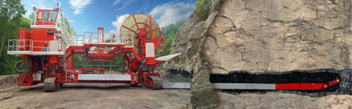
In auger mining, auger holes are bored horizontally into the coal seam from the last contour cut at the high wall. As the auger rotates and advances forward, coal is cut and pushed out of the hole by the rotating action of the auger. The action is similar to that of a carpenter boring a large hole in wood using an auger bit, and that is where the name derives. Auger mining recovers around one-third of the coal under the highwall, for whatever depth of penetration is achieved. Auger cutting heads can be as large as 7 feet in diameter and may be drilled to a depth of more than 300 feet. An auger mining machine is shown here.
A highwall, showing the auger holes is shown in this picture:
When the ultimate pit limit is reached, it is difficult to “pack up and leave” when you see the exposed coal seam. So, in some regard, the company looks at this secondary recovery technique, i.e., auger mining, as the “icing on the cake.” It amounts to coal recovery at a very low cost. It is, however, somewhat problematic and controversial. The low recovery, less than 35%, means that the majority of the reserve remains in place, but it has been sterilized, i.e., left in a condition where it will be essentially impossible for anyone to recover the remainder in the future. The holes into the side of the hill create drainage holes for acid-laden water, and that is a big problem. Surface subsidence and spontaneous combustion in the auger holes are additional concerns.
7.3.4: Highwall Mining
7.3.4: Highwall Mining
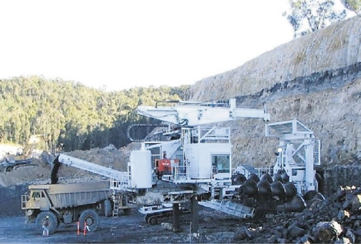
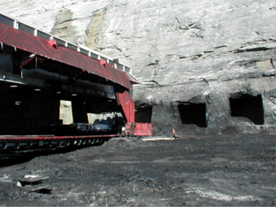
Highwall mining is very similar to auger mining in its concept, where the entry into the coal seam in made at the highwall of the ultimate pit limit. The difference lies in the use of a more sophisticated machine, known as a highwall miner. The highwall miner shares some common elements with a continuous mining machine. It has bit-laced cutting drum, and the coal is fed back through a materials handling system to the bench by the highwall, where it is loaded out. That’s where the similarity stops.
The highwall miner is equipped with sophisticated monitoring and a remote control system. It is important to maintain accurate control of the cutting head so that it remains in the coal seam, rather than drifting up or down into the adjacent rock layers, and so that a constant rib thickness is maintained between holes. Unlike the continuous miner, where a shuttle car is waiting at the tail to load out the coal, the highwall miner needs to move the coal from the cutting head to outside the highwall. Essentially, there is flexible conveyor train following the cutting head. There is a significant amount of support equipment required outside of the hole, adjacent to the highwall, to provide power and handle the cables and hoses. The computerized supervisory control system and operator station are located within the highwall miner’s structure that is located adjacent to the highwall. This picture with the artist’s cutaway shows a highwall mining machine.
What do you gain with the added complexity and cost of a highwall miner over an auger? The highwall miner can advance 1200’ under the highwall compared to a typical 300’ for an auger. Recovery rates improve from roughly 30% for an auger to near 50% for a highwall miner. The highwall miner can adapt more easily to varying seam thickness or other changes under the highwall. Its production rate can be much higher than an auger, and, in general, the unit cost of coal mined with the highwall miner will be less than with an auger. The risk of worker injuries is less with a highwall miner, primarily because the likelihood of a cave-in is less than with an auger; and attempting to remove an auger from a caved hole is fraught with dangers. On the negative side, the highwall miner does not reduce the concern over acid mine drainage.
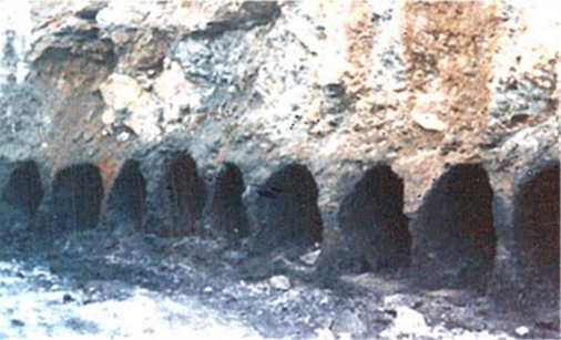
Here is a photo of the highwall showing the holes created by the highwall miner.
Lesson 7.4: Aqueous Extraction Methods
Lesson 7.4: Aqueous Extraction Methods
We’ve examined surface mining from a very general perspective, and we’ve studied the class of mechanical surface mining methods. The other major class of surface mining methods is aqueous extraction. Aqueous extraction is distinguished from mechanical extraction by one characteristic: all of the aqueous methods depend on the use of water or another liquid to extract the ore, and often the water is used to aid in the gravity separation of the valuable mineral. We’ll look at three methods within this class of mining methods: Dredging, Hydraulic mining, and solution mining. These methods are important to the recovery of certain commodities, but their overall application is limited compared to mechanical extraction methods. Here in this lesson, we’ll simply introduce the basic concepts, and leave further study to advanced courses on surface mining.
7.4.1: Dredging or Dredge Mining
7.4.1: Dredging or Dredge Mining
A dredge is the principal piece of equipment used in the dredging method and, essentially, a dredge is a boat containing specialized mining and materials handling components. Accordingly, a dredge requires a body of water in which to operate. In many cases, this is a natural body of water such as a river or a lake, but in others, it is a manmade pond or small lake. Of course, the only reason for floating a dredge is to recover something of value at the bottom of this body of water. We need to add one more condition, and that is: the material of value on the bottom must be unconsolidated, such as sand and gravel, or it must be very soft. Simplistically, the dredge is designed to lift these materials of interest from the bottom up into the dredge. Shortly, we will look at how the payload is moved in a little more detail, but for now, let’s talk for a moment about the kinds of materials that are typically recovered with this method, dredging or dredge mining.
The bottom of rivers, lakes, and harbors is often a good source of gravel. Gravel can be used sometimes in concrete as well as for a variety of other purposes such as architectural and landscaping purposes. Dredging to remove this material has the additional benefit of deepening the channel or harbor, and sometimes that is the primary purpose of dredging, and the recovery of minerals is a secondary benefit… the “icing on the cake,” so to speak!
Glaciers once covered a significant portion of the Earth’s surface, and the movement of these glaciers created extensive unconsolidated deposits of materials containing not only sand and gravel, but gold, tin, diamonds, and other heavy minerals. These alluvial deposits created by glaciation, are also known as placers. I mention this here because you will sometimes hear or read about placer mining or alluvial mining. Although these terms may be used interchangeably with dredging or dredge mining, you can’t assume that to be true in all cases. As we will see, hydraulic mining may be used in these deposits as well. Regardless, if we have a body of water covering a placer deposit, we will consider strongly using dredge to recover the minerals of interest.
Moreover, if we have such a deposit that is not underwater, but is in an area that could be easily flooded, we will consider making our own lake and then using a dredge to recover the bottom materials. If the deposit is in an area with a very shallow water table, we may simply have to remove several feet of overburden, e.g., vegetation and soil, and the excavated area will fill with water on its own. Then, we can float the dredge and mine the deposit. There are other circumstances where we could create a manmade lake to mine the deposit, but it a complicated process, because we cannot take any action that could have an adverse environmental impact.
Let’s talk a bit more about the dredge itself. A dredge is defined by the way in which it recovers the ore from the bottom. The four types are bucket-wheel, ladder, clamshell, and suction. The choice will depend on the depth of the deposit below the surface of the water and the degree of consolidation of the deposit. The size of the dredge will depend on the desired production rate and the characteristics of the body of water, e.g., depth and extent. Let’s start by looking at a picture of a dredge.
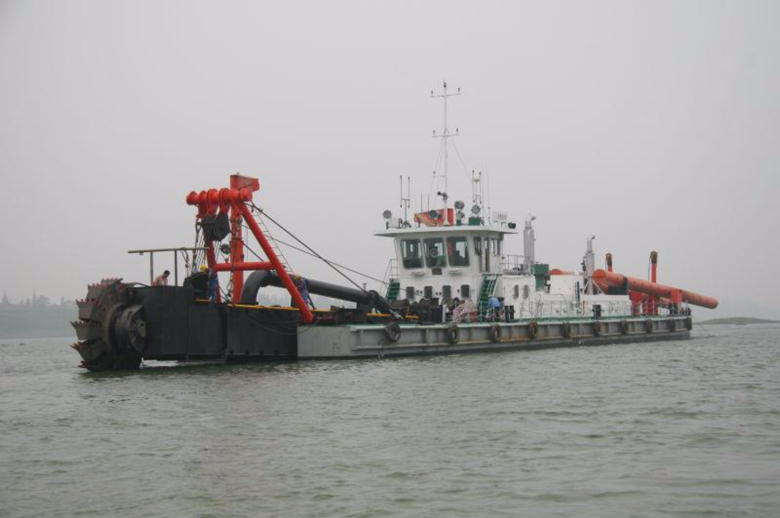
This is a large dredge, and specifically, it is a bucket-wheel dredge. You can see the bucket wheel on the left side of the picture. The bucket wheel rotates, digging into the soft material at the bottom. The dug or “mined’ material is then transfer onto the dredge. Typically, some sort of a gravity separation is employed to segregate the material of interest from the silt, mud, and other detritus of no interest. The latter is then immediately returned to the water.
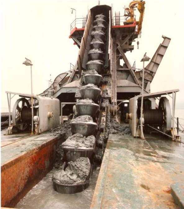
The bucket-ladder dredge is probably the most common type of dredge, as it is the most flexible method for dredging under varying conditions. The excavation equipment consists of an endless chain of open buckets that travel around a truss or “ladder.” The lower end of the ladder rests on the mine face—that is, the bottom of the water where excavation takes place—and the top end is located near the center of the dredge. The chain of buckets passes around the upper end of the ladder at a drive sprocket and loops downward to an idler sprocket at the bottom. The filled buckets, supported by rollers, are pulled up the ladder and dump their load into a hopper that feeds the separation plant on the dredge. After the valuable material has been removed, the waste is dumped off the back end of the dredge. Here is a picture of a bucket-ladder dredge, which gives a clear front view of the bucket ladder.
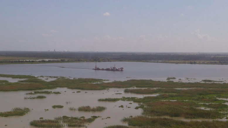
Here is a view of a bucket-ladder dredge used to mine phosphate.
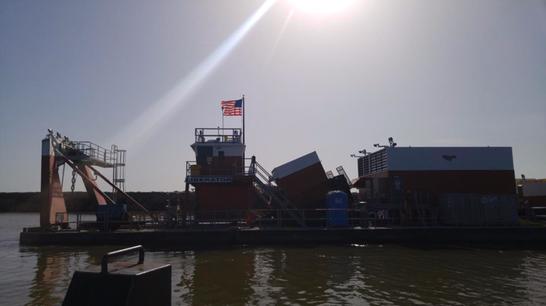
And here is that same dredge in a photo taken from a distance.
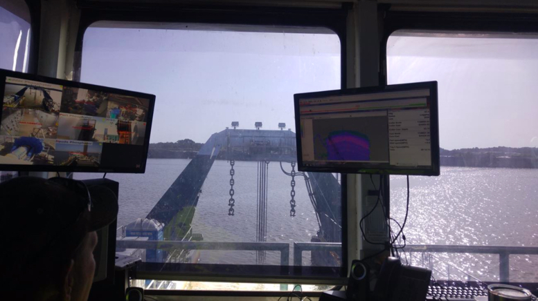
Finally, here a view from the operator's cab of that dredge. Notice the computer displays providing not only video images of different parts of the dredge but also sensor data that the operator can use to better control the operation of the dredge.
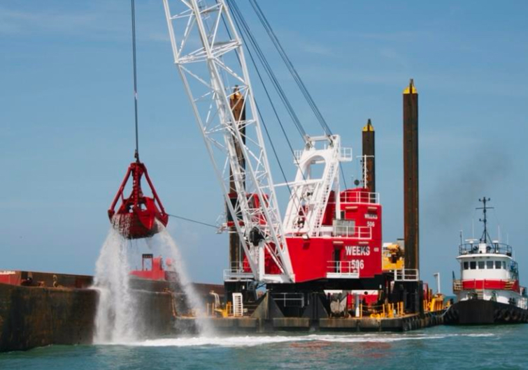
The clamshell dredge, unlike the previous two, employs a batch rather than continuous process. This type of dredge utilizes a clamshell bucket that is dropped to the bottom, scoops a bucket of material, and is hoisted back to the dredge where the bucket is dumped. This dredge can operate in deeper water than other systems and handles large material, e.g., larger rocks, well. A typical cycle time would be on the order of one minute, depending on the depth of the water. You understand the drawback of batch or discontinuous systems, and consequently, this style of dredge would only be used when its unique strengths are necessary. A typical clamshell dredge is shown here. Note the ability of this style dredge to place its payload on the dredge or on a nearby barge or structure.
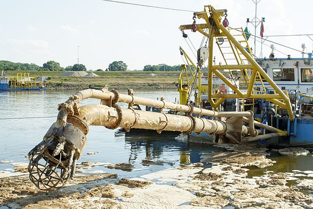
The fourth type of dredge is a hydraulic dredge. Imagine a big vacuum cleaner with a long hose – the hose is dropped to the bottom, the “vacuum” is turned on, and the material is literally sucked up the hose and captured on the dredge. Basic physics limits the amount of “lift” that can be achieved. However, the amount of lift can be supplemented with a high-pressure spray around the suction nozzle – essentially a push-pull system. This is known as hydrojet assistance. This style of dredge is suited to digging relatively small-sized and loose material such as sand and gravel, marine shell deposits, mill tailings, and unconsolidated overburden. Hydraulic dredging has also been applied to the mining of deposits containing diamonds, tin, tungsten, niobium-tantalum, titanium, and monazite. This figure diagrammatically illustrates the use of a suction dredge. Note that the use of a hydraulic pipeline to move material off the dredge is often associated with the use of this type of dredge.
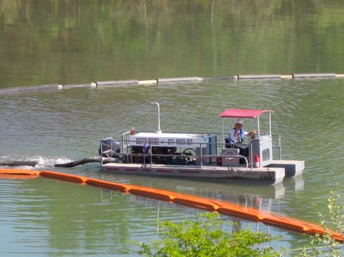
This picture shows a very small suction dredge, which might be used to clear a tailings pond, for example.
7.4.2: Hydraulicking or Hydraulic Mining
7.4.2: Hydraulicking or Hydraulic Mining
Hydraulic mining uses high-pressure water cannons, known as monitors, to dislodge relatively unconsolidated material. One of the earliest applications of hydraulic mining was to break down banks of alluvium containing gold and silver. These alluvial deposits are firm, but break down quickly upon the application of the water cannons. Of course, if digging the banks of alluvium were the goal, we could use wheeled front loaders or other traditional digging and loading equipment. The goal is not only to excavate the banks but to separate the gold, silver, or other metals from the sediments in these alluvial deposits. Toward that end, we use a gravity separation with water in a device known as a sluice. The sluice which is usually constructed, consists of a trough on a slight incline. The trough bottom may have embedded ridges. The idea is that the material laden water will flow gently down the sluice and denser materials will settle to the bottom. Toward this end, the material loosened by the water cannon is channeled to the sluice; and as it passes through the sluice, the heavier materials, e.g., grains of gold and silver, settle on the bottom of the sluice while the water and sediment are carried away.
Another important, but limited, application of hydraulicking is to break down mineral ores prior to slurry transport. Slurry transport is an important materials handling method in which a water-solid mixture is pumped over some distance. In some cases, the slurry may be pumped for 20 or 30 miles, while in others, it may be hundreds of feet. One such application is in phosphate mining. The overburden is removed, typically with a dragline, and then a monitor is used to break down the phosphate matrix into a slurry, which is then pumped to the mineral processing plant. We’re going to examine a case study in the next Lesson, and at that mine, they use a dragline to excavate the phosphate matrix and place it into a small pit where it is broken down and fed into the slurry pipeline. You’ll see some good pictures of hydraulic monitors in that case study.
7.4.3: Solution Mining
7.4.3: Solution Mining
Solution mining is the extraction of the ore through a dissolution process, i.e., we pump a solvent through the ore, the solvent dissolves the constituent of interest, and then we recover and process the resulting liquid, which is known as the solute or pregnant liquor. We can apply this method to in-situ deposits using a borehole mining method, or to mined material using a heap leaching method. In-situ, which implies “in-place” “in-the-seam”, and using an in-situ method, means that we extract, i.e., dissolve, the material of interest within the deposit and leave behind the gangue or waste minerals. In-situ recovery has the advantage of not disturbing the surface with a mining activity and of eliminating surface piles of processing plant tailings or waste. It has the disadvantage in some applications of creating a potentially hazardous environmental situation if the solvent or solute can migrate into the environment. Let’s talk about the in-situ methods first.
7.4.4: Borehole Mining Method
7.4.4: Borehole Mining Method
One hole is drilled into the deposit for the purpose of pumping the solvent into the deposit, and one is drilled at some distance from the other to recover the solute. The solvent flows between the two holes creating a cavern where the ore was dissolved. For some minerals such as common salt (NaCl) or trona, water is the solvent. For other minerals, a chemical solvent is required. Interestingly, sometimes these caverns are of greater value than the extracted mineral! In the Louisiana salt domes, for example, the caverns are used to store crude oil and natural gas. Often, multiple holes are drilled within the area of interest. Occasionally, only one hole is drilled, but the borehole is divided into an inner and outer annulus so that the solvent is forced down one, and the solute is retrieved through the other. This is the case for the Frasch process for recovering sulfur. The Frasch sulfur process uses steam to melt and dissolve the sulfur in the water, which is then forced back up the borehole; or, in other cases, the melted sulfur is allow to drain and collected in subterranean pools where it is then pumped to the surface.
7.4.5: Heap Leaching Method
7.4.5: Heap Leaching Method
Heap leaching was first used to extract very low grades of metal ore from piles of plant tailings or waste rock. In the case of copper, for example, a solution of sulfuric acid was released at the top of the pile and allowed to percolate down through the pile. The effluent was collected and washed over scrap tin. The copper would precipitate out on the tin, the tin would then be smelted, and the copper would be separated from the tin. All-in-all, it was a fairly clever and economic process to extract metal from material that otherwise would have been discarded as waste. Unfortunately, there was no thought given to the consequences of the effluent seeping into the ground, and in the end, this practice resulted in massive pollution around the mine site. The old Anaconda Copper Company mine in Butte, Montana, for example became an EPA Superfund Site! Today, heap leaching is practiced, but with proper engineering controls in place to ensure that it proceeds with no damage to the environment. Among other precautions, extensive containment barriers are constructed with multiple levels of redundancy.
Today low-grade ores are “mined” on the surface and placed on these containment pads so that the valuable metal can be leached out of these “heaps.” This is an important method for recovering gold from low-grade ore that could not be economically processed by any other means. The mining of the low-grade ore is usually by large dozers, front loaders, and trucks. Usually, the depth of the excavation is quite limited, and two of the reasons for this are that as the deposit depth increases, the grade may improve to allow economic exploitation by another mining method; and the cost of excavating this low-grade ore increases with the depth, and quickly it becomes uneconomic. The time required for the leaching to be completed can vary from weeks to years, with the latter being more common; and during this period, bacterial action, as from metal oxidizing bacteria for example, is critical to the success of the process. A variation of heap leaching involves constructing the “heap” in a dump, and calling it dump leaching. Large containment vessels are being used on a limited basis as well.
Both heap leaching and borehole mining have become the favored exploitation methods for recovering uranium. This figure illustrates a heap leaching operation.
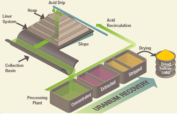
This figure illustrates the process at Uranerz’s Nichols Ranch Mine. This is a good example of how a borehole mining method is employed for in-situ recovery of a mineral.
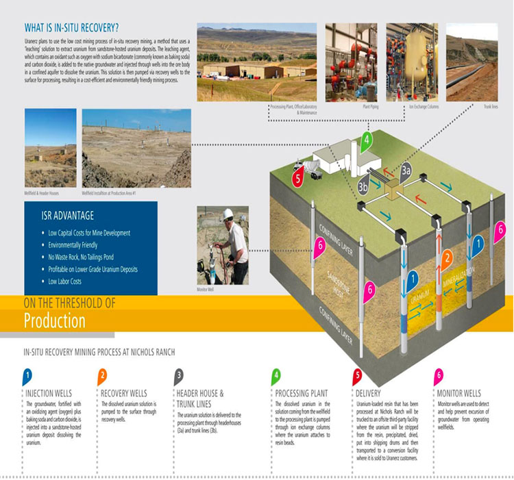
Lesson 7.5: Case Study - Phosphate Surface Mine
Lesson 7.5: Case Study - Phosphate Surface Mine
We’re going to take a close look at one mine in this lesson – a surface mine in Florida, from which phosphate is obtained. This mine utilizes an open cast method to expose and extract the phosphate ore, or phosphate matrix as it is known; and then they use hydraulicking to breakdown the matrix. The resulting slurry is then transported several miles in a slurry pipeline to a mineral processing plant.
I’ve got some good pictures and videos that will help you to better understand the material that we’ve been covering in this module on surface mining. I don’t intend to ask you a lot of specific questions about this phosphate mine, but, hopefully, this case study will help you to better answer questions about mine planning and the mining methods in general.
We’ll start out by learning a few facts about the phosphate industry, and then we’ll quickly move into the details of this mine’s operation. I also want to acknowledge Mosiac for allowing me to tour their mines and work with their staff, and for providing many of the photos and videos in this lesson. Mosaic is a world leader, not only in the mining of Phosphate, but in their approach to sustainable mining. They hire a high proportion of engineers to work at their mines and processing facilities, and they run a first-class internship program for mining and other engineers.
7.5.1: Overview of the Phosphate Industry
7.5.1: Overview of the Phosphate Industry
Phosphate is a key component in agriculture (food production)
- granular mono ammonium and diammonium phosphate pellets for fertilizer
- animal feed supplements
- elemental phosphorous for food-additive applications.
A limited amount of elemental phosphorus is used in other industrial applications.
In 2015, Phosphate rock was mined by 5 companies at 11 mines:
- in 4 states
- 80% in Florida and North Carolina & 20% in Idaho and Utah
- to produce 27 million tons of marketable product with a value of $2.4 billion fob mine
World Mine Production and Reserves (USGS Minerals Commodity Survey)
| Country | Mine Production, 2013 | Mine Production, 2014 | Reserves |
|---|---|---|---|
| United States | 31,200 | 27,100 | 1,100,000 |
| Algeria | 1500 | 1500 | 2,200,000 |
| Australia | 2600 | 2600 | 1,030,000 |
| Brazil | 6000 | 6750 | 270,000 |
| Canada | 400 | --- | 76,000 |
| China | 108,000 | 100,000 | 3,700,000 |
| Egypt | 6500 | 6000 | 715,000 |
| India | 1270 | 2100 | 35,000 |
| Iraq | 250 | 250 | 430,000 |
| Israel | 3500 | 3600 | 130,000 |
| Jordan | 5400 | 6000 | 1,300,000 |
| Kazakhstan | 1600 | 1600 | 260,000 |
| Mexico | 1760 | 1700 | 30,000 |
| Morocco and Western Sahara | 26,400 | 30,000 | 50,000,000 |
| Peru | 2580 | 2600 | 820,000 |
| Russia | 10,000 | 10,000 | 1,300,000 |
| Saudi Arabia | 3000 | 3000 | 211,000 |
| Senegal | 800 | 700 | 50,000 |
| South Africa | 2300 | 2200 | 1,500,000 |
| Syria | 500 | 1000 | 1,800,000 |
| Togo | 1,1110 | 1200 | 30,000 |
| Tunisia | 3500 | 5000 | 100,000 |
| Vietnam | 2370 | 2400 | 30,000 |
| Other Countries | 2580 | 2600 | 300,000 |
| World Total (rounded) | 225,000 | 220,000 | 67,000,000 |
There are three sources of Phosphate Rock
- Sedimentary deposits of marine origin
- Africa, China, Middle East, and United States
- Igneous and metamorphic deposits
- Brazil, Canada, Finland, Russia, and South Africa
- Biogenic deposits from bird guano
High-quality sedimentary phosphate deposits are mined in the U.S.
The mined phosphate rock is beneficiated by a process in which the phosphate rock is reacted with sulfuric acid to produce an intermediate feedstock of phosphoric acid.
Gangue minerals associated with the deposit impact the cost of processing the ore
Clays and silica are the only significant gangue minerals in these high-quality deposits Carbonates are present in significant amounts in lower-quality depositsThe gangue minerals can require larger quantities of reactants (sulfuric acid), which significantly increases production costs, and can increase time require for downstream processing, e.g., filtration; and they can interfere with the ore recovery and concentration in downstream operations, e.g., float processes.
Carbonates are more problematic. Dolomite, for example, shares mineralogical similarities with phosphate, and this makes it more challenging and expensive to remove it.
- Major gangue minerals of primary interest in U.S. operations:
- dolomite, calcite, silica, and clays
- Certain other gangue components may need to be removed during or after the production of the phosphoric acid:
- cadmium, radium, uranium
- Clay slimes are removed in log washers or hydrocyclones.
- Silica is removed using the well-established Crago double float process.
7.5.2: MOSAIC Florida Phosphate Operations
7.5.2: MOSAIC Florida Phosphate Operations
I suggest that you go to Mosaic’s website [30] to learn more about the company. Doing so, you will arrive at this "Who We Are" page, and you will note that Mosaic is not only a major producer of phosphate but also of potash!

Their Florida operations are located in five counties of southwest Florida, as shown on this map. This is a rural area of Florida.
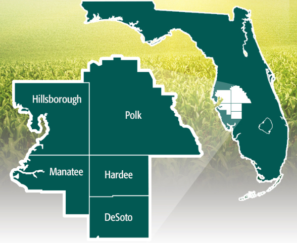
Resource
The phosphate rock deposit consists of a matrix of phosphate pebbles, clays, and sand, along with other gangue such as silica. (Carbonates occur in increasing amounts in the lower quality deposits.)
Key Characteristics
- The matrix is relatively unconsolidated and is typically on the order of 10’ thick.
- It is covered by an average overburden thickness of 30’ ranging from 15’ to 50’.
- The overburden is unconsolidated sand and organic matter.
- The matrix is underlain by a hard limestone.
- The water table is near the surface throughout the region.
Given these key characteristics, you should be able to choose the mining method. Can you do so? Well, at the beginning of the lesson, I told you that they employed the open cast method. Nonetheless, I would hope that you could come to that conclusion on your own. The use of hydraulicking on the other hand, would not be apparent to you.
Let me tell you the overall sequence of operations to remove any mystery!
- Prepare the site for mining
- dozers
- Install utilities
- electric power
- water drainage
- “Pitsrdquo; for breaking down the matrix with monitors
- slurry pumps and pipelines
- Remove overburden
- dragline
- Mine the ore
- dragline
- Prepare for the ore for hydraulic transport to the plant
- hydraulic monitoring to break-up matrix
- Backfill the cut
- dragline
- Reclaim the site
- sand tailings pumped to the site
- level spoil piles and grade
- dozers
- loaders
- hydraulic excavators
- add top layers
- revegetate
We’ll take a look at many of these in more detail; but now, let’s start with an aerial view of the mine.
7.5.3: Welcome to the Operation
7.5.3: Welcome to the Operation
This picture was taken by a Penn State mining engineering intern while riding in the company helicopter!
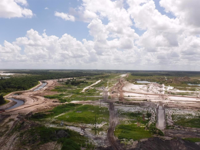
The features in this photo will become known to you as we continue.
Best Management Practices (BMP) features and land development
Off to the left side of the photo, you see a waterway that looks like a nicely manicured stream or small river. It is manmade, and it is done to control the water table around the mine and ensure that the water table outside of the mine’s perimeter is not lowered or otherwise harmed. At these mines, this “ditch” is known as a best management practice ditch, because it is part of their stormwater pollution prevention plan (SWPPP) required under the Clean Water Act, and is considered a “best practice” to accomplish the intended goal.
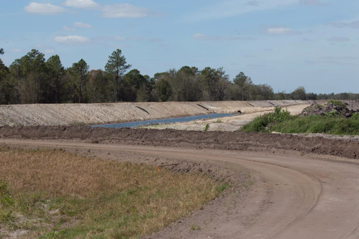
The construction of the BMPs precedes other development activities. Once completed, roadways are constructed into the site, vegetation is cleared, and the top soil layers are carefully placed away from the active site for use during reclamation. Then, the site will be graded and leveled to provide a working surface for the draglines.
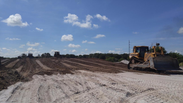
7.5.4: Infrastucture Installation
7.5.4: Infrastructure Installation
Once a level site has been prepared, the work of placing utilities will begin. In this photo, they are placing high voltage cable (yellow in color), which will supply power for the dragline as well as the many pumps used on the site.
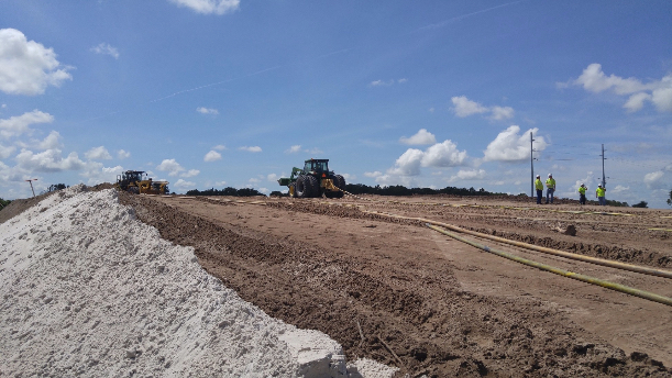
As work on the electrical power infrastructure is continuing, a series of dewatering holes will be developed. This photo shows the electrical infrastructure, and do note the overhead electrical lines in the background and the electrical installation in the foreground. If you look closely, you can see 6” diameter PVC pipes protruding at the surface of the ground. These are dewatering holes.
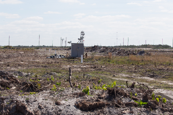
This next photo gives us a close-up view, and we can see other important features. There is a small pump at the bottom of this hole, and you can see the small discharge line, where the pumped water enters a larger diameter collection pipe that is serving the entire row of dewatering holes. You can also see the electrical cable that goes down the hole to the pump at the bottom. These holes go to the bottom of the matrix, and so, a typical hole would be 50 – 60’ deep. Those pretty pink flags that you see are markers so that equipment, such as tractors and pickup trucks, don’t accidentally run over and damage pipes or electrical cables.
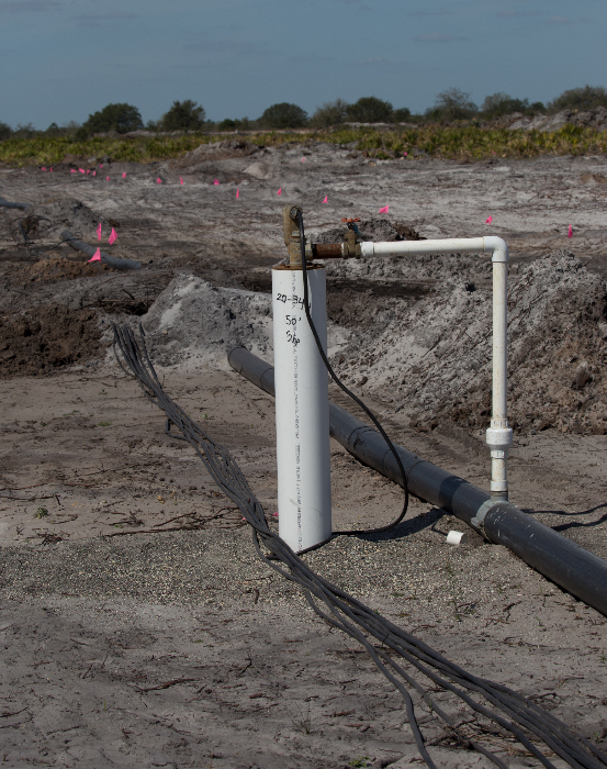
This next picture focuses on an electrical installation. As is often the case, this equipment is mounted on a skid so that it can be attached by a wire rope to a dozer and pulled to a new location. This equipment provides the hardware to allow a connection to overhead power lines, if required, a transformer to step the voltage down to a level required by the machines and pumps, and protective devices to allow switching and implementation of other safety features.
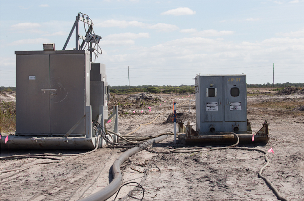
7.5.5: Overburden Removal
7.5.5: Overburden Removal
With the utilities in place, we are ready to install the pits and monitors and to begin overburden removal. Let’s talk first about overburden removal. A typical dragline in use at the Mosaic mines in Florida is shown in the next picture. Remember, we talked about how draglines move – they walk. Look at the two big walking shoes on this dragline, one on each side. The shoe is green and there is a yellow guardrail around the top surface of the shoe. As you might imagine, these things don’t break any land speed records!

Here is another aerial view of the mine, but in this one, you can clearly see the dragline at work.

Here is a close-up of the dragline removing overburden. If you look to left, you can see the last strip or cut that was mined (it is now filled with water).
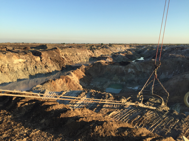
This short video clip (2:11) will give you a feel for the overburden removal cycle. Note the development activities ongoing to the left of the active cut.
In this video clip, you probably saw the greenish colored material at the bottom. That is the phosphate matrix, and in this next picture, you can see it as well.
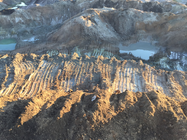
Evaluating the Phosphate Matrix
You’ll recall from our discussion of mine planning, that mineral processing plants are designed to perform best when the feed into the plant has characteristics that lie within a fairly narrow range. When the mined material is outside of this range, the practice is to blend loads of material from different mining faces to achieve the desired feed to the plant. This is true in phosphate mining as well. How do you know the qualities of the ore being mined at a given location on a given day? You send in the geologists to take samples and visually inspect the ore. In this next picture, you can see the geologist, accompanied by operations personnel, preparing to sample the phosphate matrix in the drag bucket.
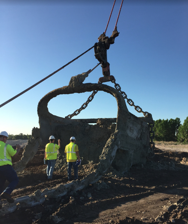
Now that we have a clearer understanding of this phase of the operation, let’s look at the dimensions of a typical strip or cut.
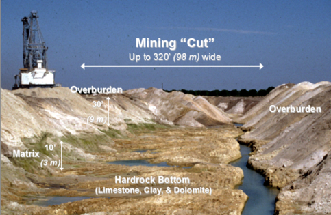
7.5.6: The Mining Operation
7.5.6: The Mining Operation
Before the dragline can begin to mine the ore, the hydraulic monitors must be set up and ready to go. That work will be occurring while the dragline is removing overburden. Let’s start out by looking at a completed installation which is in operation. In the following video clip (0:35), you will see the dragline dumping the phosphate matrix into a constructed “pit.” There, the monitor blasts the matrix into fine particles. The slurry pours out of the pit, through the iron grate that is designed to keep large chunks from passing, and into a sump where the slurry is drawn into the pump and transported into the slurry pipeline that goes back to the plant. The video clip is 35 seconds in length, but actually represents about 10 minutes of actual work. In other words, you are seeing it in fast motion!
7.5.7: A Closer Look
7.5.7: A Closer Look
Let’s look at this construction in more detail. Looking at the next picture, we have a hole that has been dug, and they call it a “pit.” The pit is bisected by the steel grate, which they refer to as the “pit trap.” To the left of the grate, we have the hydraulic monitor, and this is where the dragline deposits the phosphate matrix. On the right side of the grate, we have the slurry intake pipe. In this photo, the intake has been lifted above the water line. Normally, the intake is submerged below the water line.
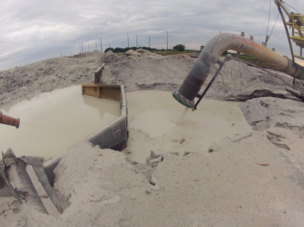
In this next photo, we can see more clearly the construction of the pit and pit trap.
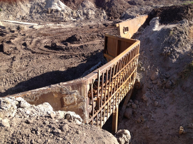
The next step in the construction of the pit is to install the monitor. Small dozers are used to construct the pit and to do the grading around it. In this next photo, look to the right of the worker. Do you see the specially outfitted tractor with the winch/crane assembly? This is what they use to move and position the monitors, pit traps, pumps, and related assemblies.
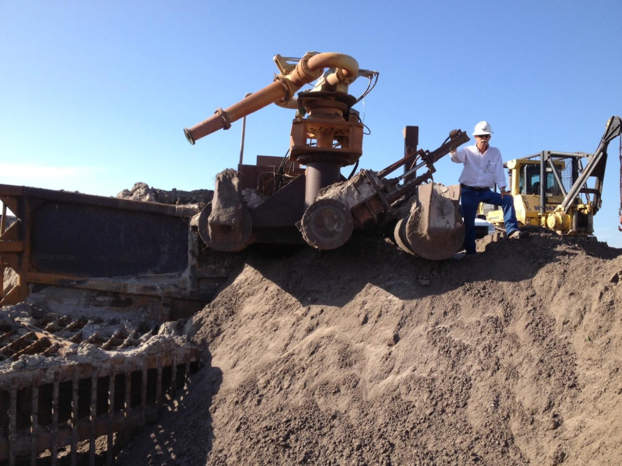
The next picture provides a wide-angle view of the pit and related equipment.
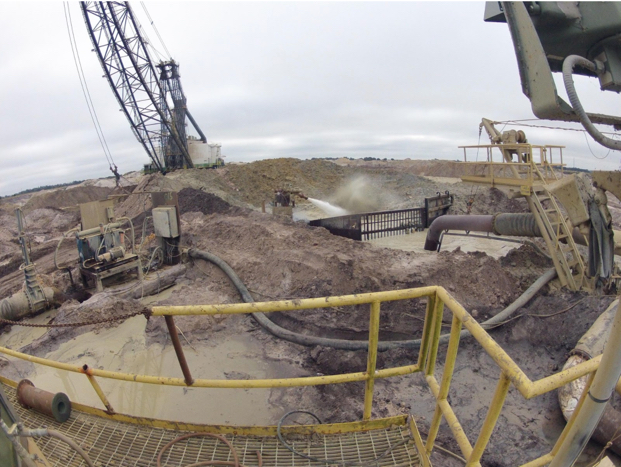
7.5.8: Construction of a New Pit
7.5.8: Construction of a New Pit
Now, with this understanding of the individual components, let’s watch a video (8:57) showing the construction and set up of a new pit. Note all of the related activities in the background.
Of course, as mining advances, it becomes necessary to move the pit to the next location. This is a process accomplished over a shift. The next video, which is about 6 minutes in length, captures a complete move over a nine-hour period. Fasten your seatbelts!
The design of a slurry transport system is covered in our materials handling course, MNG 404. Here, it is worth noting a few defining characteristics of the system used at the Mosaic mines.
- 2000 tph capacity
- 1500 hp or greater pump motors
- up to 62” diameter pump impellers
- pipelines up to 10 mi long
- 20” diameter pipe
- pumps every 1 mi
- slurry
- 35% solids by weight w/ up to 6” – 8“ size fraction
Finally, we can take a look at the placement of overburden into a previously mined cut.
7.5.9: Reclamation
7.5.9: Reclamation
Reclamation is the final part of the sequence of operations, and as you know, it is an ongoing activity. Mosaic does a stellar job of reclaiming the land, and given the growing conditions in Florida, within months after mining has been completed, the area appears undisturbed and back to its original appearance. Actually, that is not always true – often the reclaimed area is suitable for a higher purpose than the overgrown scrub areas that preceded mining. On their website, they discuss the reclamation activities in more detail.
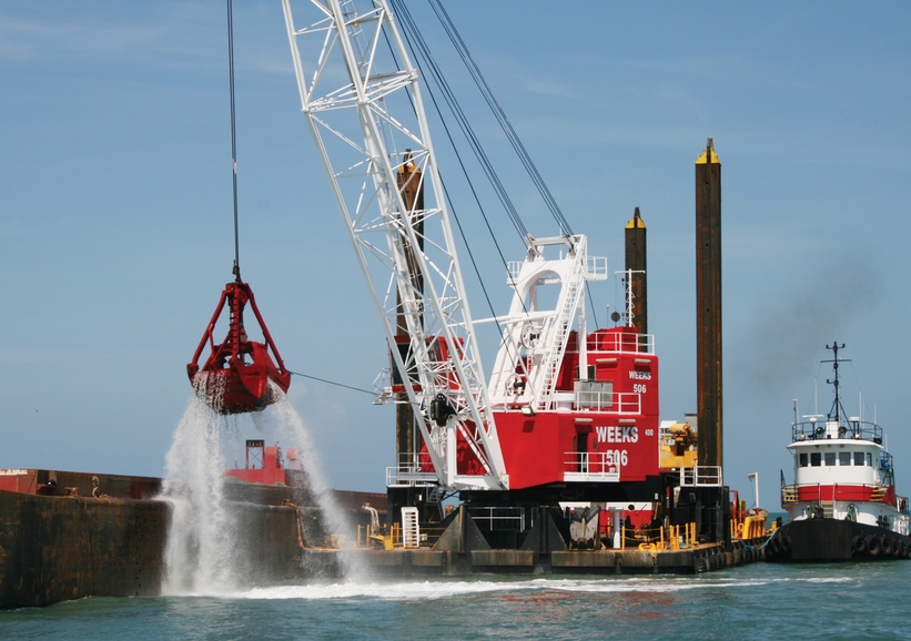
With that, our case study and the module on surface mining comes to an end!