Lesson 5.1: Introduction to the Cycle of Operations
Lesson 5.1: Introduction to the Cycle of Operations
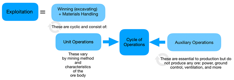
The process of exploitation reduces to two fundamental operations: winning, i.e., freeing the ore from the orebody, although that term is rarely used in ordinary conversation; and materials handling, i.e., transporting the ore to the mineral processing plant. Winning and handling are repeated over and over again, i.e., they are cyclic.
The fundamental processes of freeing the ore fall into two categories. In softer deposits, we can use equipment to excavate or essentially “dig” the ore. In harder material, we will have to use explosives to blast the ore free from the orebody, and to blast the ore, we must first drill holes to place the explosive that will be used. Once the ore has been freed, it must be loaded so that it can be hauled.
Thus, the two fundamental operations defining the exploitation of ore, winning and materials handling, consist of the following unit operations:
Harder Materials: drill, blast, load, and haul
Softer Materials: excavate, load, and haul
These unit operations also define what is known as the basic production cycle.
Obviously softer and harder are relative terms and are deliberately vague. The compressive strength is an important parameter to separate ores into the “softer-harder” categories, but other parameters can affect whether or not it is practical to excavate rather than drill and blast. Moreover, as cutting technology improves, it is becoming practical to excavate materials today that we wouldn’t have considered twenty years ago. Examples of softer ores that can be excavated include coal, salt, and trona. Examples of harder ores that require drilling and blasting include limestone, copper, and lead. Some ores, for example, salt and potash, are exploited both ways. We will discuss the reasons for that in this lesson.
Every mining method, with the exception of solution mining, employs these unit operations. (We could force fit solution mining into this paradigm, but it would be a bit weird, so we’ll not do so. Besides, solution mining accounts for a very small amount of all mining.) The specific equipment chosen to implement each of the unit operations may vary by mining method, and even within methods there may be equipment and practices variation. In this Module, we’ll focus on the overarching principles, and we’ll take a look at the equipment that is commonly used.
There is one other category of common operations known as auxiliary operations. Auxiliary operations support the production cycle and are essential to it, and like the unit operations, they are repeated over and over again; and as with the unit operations, the specifics of the auxiliary operations will vary by mining method and the characteristics of the orebody. We’ll say a few things about the auxiliary operations in this Module, but save most of our discussion on these for when we look at the mining methods. The list of auxiliary operations can become quite long if you attempt to include every single activity that must occur during mining. We’re not going to try to do that, but a few are of special note.
Ground control and power are two auxiliary operations that are essential to every mining method. In underground mines, these two would be augmented with ventilation as an essential and major auxiliary operation. In surface mines, an argument could be made that reclamation would be an essential and major auxiliary operation. Others would argue that maintenance should be on the list of essential and major auxiliary operations. There are other auxiliary operations that are more specific to the method, such as preparing and placing backfill in mines employing the cut and fill method; or commodity, such as the explosion prevention activities in mines, regardless of method, that have explosive gas.
Taken together, the unit operations and auxiliary operations constitute the cycle of operations, which will be different among the different mining methods. Accordingly, we will discuss and document the cycle of operations that are inherent to each when we look at the individual methods in more detail.
In this Module, we’ll examine engineering concepts that apply to unit operations, which will then facilitate a more detailed analysis when we look at the specific mining methods, and we’ll identify the names and general characteristics of the equipment used for these operations. In the remainder of this lesson, I want to introduce you to the equipment used in the production cycle.
5.1.1: Equipment for Winning the Ore
5.1.1: Equipment for Winning the Ore
Commonly used equipment for winning the ore includes the items listed below. The selection of a specific size or type of equipment generally requires an engineering analysis. Here, the goal is simply to familiarize you with the name and function of the major pieces of equipment.
5.1.1a: Drills, Explosives Loaders, and Rippers
5.1.1a: Drills, Explosives Loaders, and Rippers
Drills
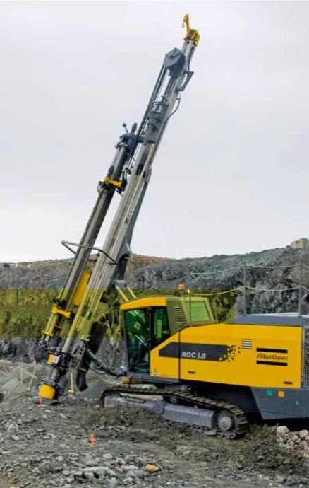
Drills are used to create a hole of a certain diameter and depth. Occasionally, the goal of drilling is to create an empty hole, but more often, the purpose of the hole is to accept explosives. The major components of a drill include the bit, which fragments the rock; a power source that transfers energy to the bit; and lengths of drill steel, sometimes called the drill string, that connect the bit to the drill rig proper. Drills vary by: the method of rock penetration, e.g., rotary or percussion; the location of the power source, which can be at the top of the drill string, e.g., top hammer, or at the bit, e.g., down-the-hole; primary method of powering the drill, e.g., diesel engine, electric motor, or compressed-air; and the method of mounting the drill rig, e.g., track-mounted or tire mounted.
Here, we have a track-mounted down-the-hole drill with an articulating boom to facilitate drilling holes at precise angles.
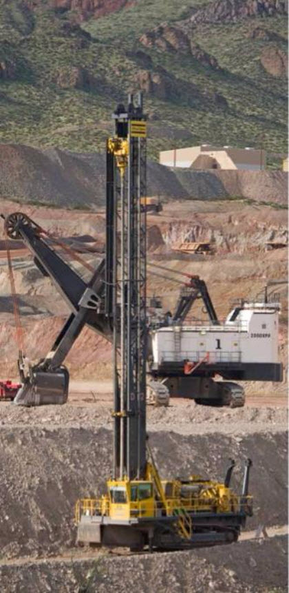
While the previous drill employs a down-the-hole hammer to apply energy to the bit, this one is a top-hammer drill, i.e., the energy source for the bit, at the top of the drill string. That means the “pounding and rotational” action has to be transmitted through the drill string to the bit. The biggest disadvantage of this approach is the loss in accuracy. The drill string tends to travel in a large helical track with the top hammer, and this causes the drill bit to “wander” off the desired location of the hole.
If these drills are going to be used underground where the headroom is limited, the mast is not as high but otherwise the drill is similar. While the accuracy of hole location is most always important, in some underground applications, it is crucial. In those, a down-the-hole hammer will be used.
Vertical or inclined holes are commonly required in surface mining, and sometimes in underground mining. It is very likely that horizontal or nearly horizontal holes will be required in underground mining, as well as overhead vertical or overhead angled holes.
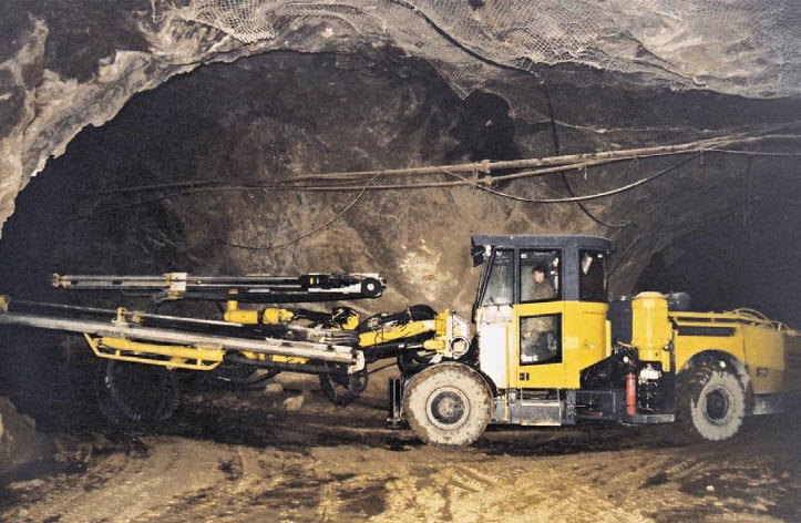
The dual boom jumbo drill is designed to drill horizontal or inclined holes at angle off of the horizontal. The depth of these holes is typically limited by the application and is on the order of 15’.
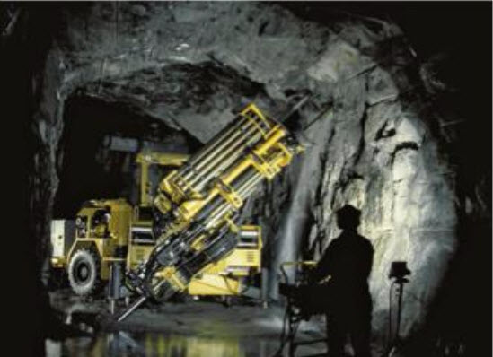
Ring or fan drilling and longhole drilling are characteristic of a few underground metal mining methods. The holes may be 150’ or long, and must be drilled to precise depths at the exact design angles. Drills to accommodate these requirements employ computer control to achieve the required accuracy, as do more and more jumbo and other drills being used in production operation. A typical drill is shown here. Note the remote operating station for the drill operator.
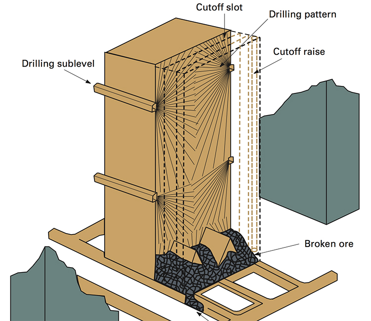
This diagram illustrates the drilling pattern required in a sublevel stoping mine. Notice the layout of the holes. What do you think would happen if a hole was started, but the angle was off by a few degrees? Or what if a particular hole were drilled to 128’ instead of the designed length of 135’? Intuitively, I am sure you can imagine that it will affect the performance of the blasting, and you are correct. We’ll talk more about this when we cover blasting, but for now, please recognize that productivity, cost, and safety are adversely affected by less-than-optimal drilling practices.
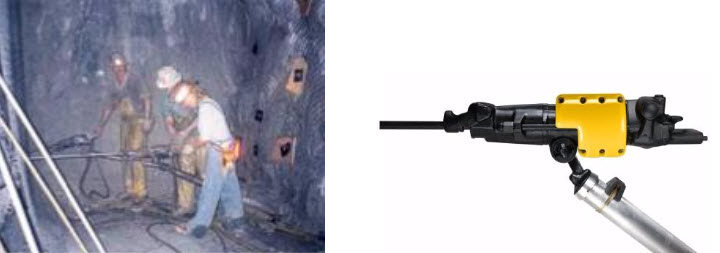
Finally, we should close our overview of drills with the handheld “jackleg” drill. In years past, these were used instead of jumbo drills in hardrock mining and for ground control applications in coal and metal/nonmetal mines. The size hole depended on the cylinder bore of the drill, as they were powered by compressed air, as well as the size of the drill bit. Hole sizes ranged from approximately 1” to 4”. Depending on the size, and consequently what the drill was used for, they were given names such as drifters or stopers. They are only used in modern mines for very specialized functions, requiring a few holes on occasion, here or there. Unfortunately, you will find them in widespread use in the underground mines of lesser-developed countries. I say unfortunately because they are brutal to use. Although much of the weight, around 75 lbs., is supported on the jackleg, the miner has to apply the thrust, i.e., pushing the drill bit into the hole. That alone is hard work. They are very loud, there is bone-jarring vibration, and they can produce dust-laden air and that along with the oil mist from the compressed air creates a respiratory hazard. Teams of miners would stand all shift-long operating these drills. Often they were paid based on the production that they achieved, and 15 years ago in the western U.S., one of these miners could easily earn $60-80 thousand dollars per year… but they earned every penny of that!
The practice of loading sticks of dynamite has all but disappeared from modern mining. Safer and more economic practices utilize explosives that are pumped, gravity-fed, or pneumatically blown into the hole. That’s not to say that we never use packaged material, because we do, and we’ll look at that when we discuss explosives and blasting practice. The vast majority of blasting, however, is accomplished with powders, gels, or emulsions that are bulk loaded.
Explosives Loaders
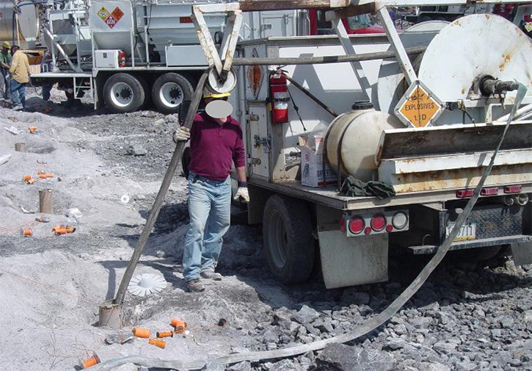
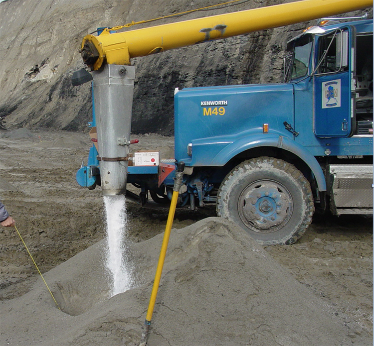
The truck below is used in surface mining. It carries the materials to mix the explosive at the hole, and the equipment to place the explosive into the hole. Such an arrangement can be found in some underground mines as well. In this example, the explosive is being pumped into the hole.
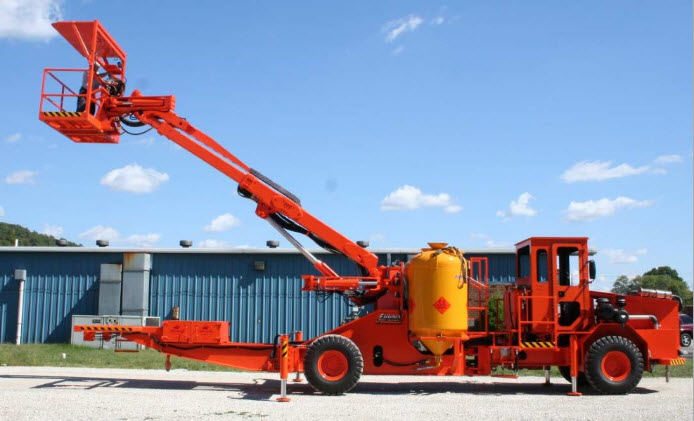
In a mine in which the height of the active mining face is on the order of 15’ to 60’ feet, you will see equipment like this. The boom allows the blaster, standing in the basket, to reach each hole, insert a hose into the hole, and then load the explosive. In this picture, you can see the yellow tank that contains the blasting agent. There is a second tank on the other side, which is obscured from view in this photo. These tanks are known colloquially as “powder monkeys.”
Rippers
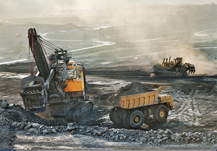
Rippers are dozers that have been equipped with one or more large drag bits. These are pulled through the ore as the dozer moves forward. Typically, they break up the top 6” – 18”, depending on the mechanical properties of the ore. Rippers are not very common because they are suited to few deposits. Occasionally, I’ve seen them used in soft high calcium limestone and in coal, but there are other examples. In the picture here, this ripper (seen at the back of the image) has three large drag bits.
5.1.1b: Loading, Draglines, Shovels, and Hydraulic Excavators
5.1.1b: Loading, Draglines, Shovels, and Hydraulic Excavators
You’ll recall that the production cycle for harder ores is drill-blast-load-haul; while for softer ores, it is excavate-load-haul. I am emphasizing load because I want to talk about the equipment used for loading. In harder ores, the material is broken free of the orebody by drilling and blasting. Once it is freed, it usually must be loaded into something so that it can be hauled out of the mine. In softer ores, if a ripper is used, the broken ore will require loading. In softer ores, it is often practicable to free them from the orebody by digging or excavation, without the need to drill and blast. Once freed, the ore is usually loaded into something so that it can be hauled out of the mine. By the way, I am using the word something to describe the haulage out of the mine. I’ll be more specific shortly when we look at haulage.
The reason for this quick review of the difference in production cycles is because the equipment used in loading harder ores is sometimes used for both excavating and loading softer ores. I want you to be aware of this now so that you are not confused when we encounter this with certain pieces of loading equipment.
Draglines
Draglines have the ability to excavate huge quantities of material and then to place that material at quite a distance from the dragline itself. Here are some of the more important characteristics of draglines.
- The drag bucket is filled by pulling (dragging) the bucket towards the dragline.
- The dragline can only dig at a level below the level at which the dragline is sitting.
- The drag bucket is outfitted with “teeth” to aid excavation, but even so, it is only effective in softer materials or materials that have been blasted.
- The size of the dragline is based on the capacity of the drag bucket. A 15 yd dragline has a bucket capacity of 15 yd3. Typically draglines are in the range of 60 – 150 yd. The largest one ever built had a bucket capacity of 220 yd3. It could fill the bucket, swing it to the dump point nearly 300’ from the machine, dump the bucket, and return to begin the cycle over again in 45 seconds!
- The reach of the dragline determines the distance from the machine that material can be dumped. The maximum reach is approximately 450’.
- The weight of the dragline is so great, approaching 8000 tons in the larger units, that crawler tracks are used on only the very smallest draglines, and instead, they sit on two large “shoes” to distribute the weight. The shoes are attached to powered eccentric cams that allow the dragline to walk as mining advances.
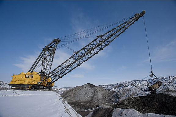
Draglines are commonly used to remove the overburden, also known as stripping, in open cast mining. In many cases, the overburden is drilled and blasted to facilitate removal by the dragline. Occasionally, the dragline will be used to remove the ore as well.
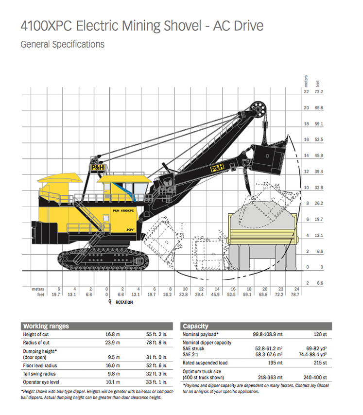
Shovels
Shovels have the ability to load large quantities of material, but less than draglines. A major difference between a shovel and dragline is that a shovel loads material at the same level as the shovel is sitting up to the height of the shovel’s boom. Here are some additional characteristics of shovels.
- The shovel’s dipper is filled by pushing the dipper into a bank of material. This action is known as crowding.
- The dipper is outfitted with “teeth” to aid excavation, but even so, it is only effective in softer materials or materials that have been blasted.
- The size of the shovel is based on the capacity of the dipper. A 12 yd shovel has a dipper capacity of 12 yd3. Typically, shovels are in the range of 10 – 90 yd.
- The digging height of the shovel is determined the size of the boom.
- Shovels are mounted on large crawler tracks, to facilitate movement into the bank, known as propelling; as well as to allow the shovel to move to the working faces or banks.
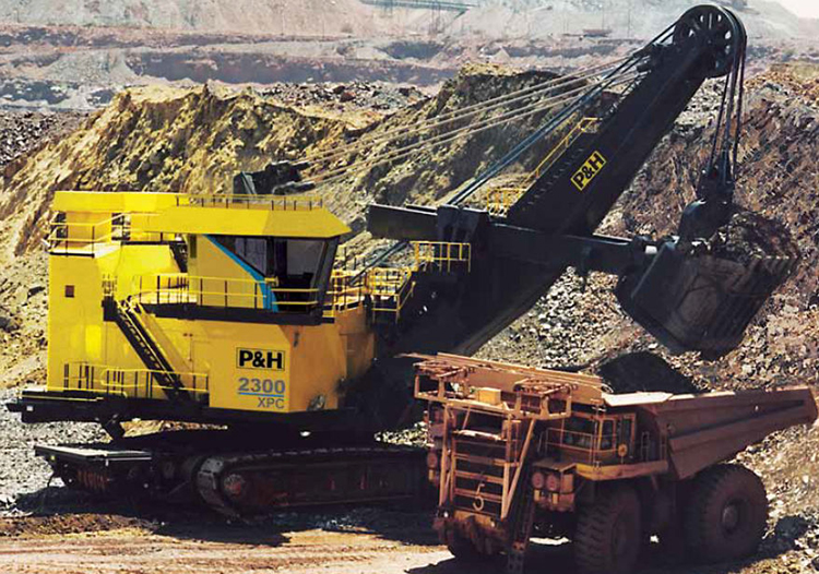
Large shovels are used for overburden removal, and in this application are known as stripping shovels. Perhaps more commonly, they are used to load ore into trucks. The relationship of key shovel parameters is illustrated in this diagram. Also, I’d like you to take notice of the wire ropes that are used to control the boom and the dipper. This is the original configuration for shovels. Over the past three decades, a modification of the shovel, using hydraulics cylinders instead of wire ropes, has become increasingly popular. Let’s take a look at it next.
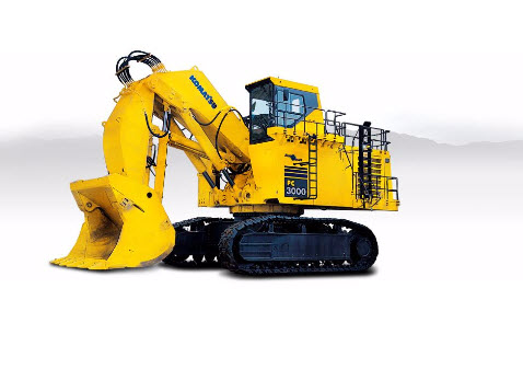
Hydraulic Excavators
This class of loader had its origin with machines that looked like this. These excavators had the advantage of being able to excavate or load below or above the level at which the machine is sitting. They also have the ability to be rather selective in what they remove.
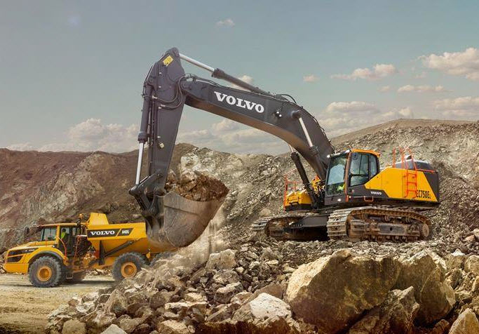
These excavators have gotten much larger over the years and have buckets of 40 yd3 or more, and a reach of 60’ or more.
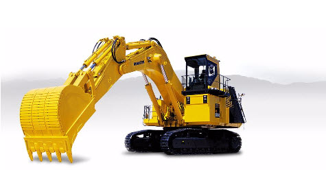
The wire ropes on electric shovels have been replaced with hydraulics, and this has led to hydraulic excavators that look like this, and are often called hydraulic shovels. By replacing the wire ropes, additional degrees of freedom can be incorporated into the machine, resulting in better performance.
5.1.1c: Wheeled Loaders, Scoops and LHDs
5.1.1c: Wheeled Loaders, Scoops and LHDs
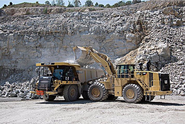
Wheeled loaders are mobile and maneuverable, and commonly found in surface and underground mining applications. The bucket typically ranges in size from a few yd3 to 10yd3. The high-lift linkage allows loading of the largest haul trucks available. These loaders are capable of digging soft and unconsolidated materials but are most commonly used for loading material that has been blasted. Chains are often put on the tires to increase the traction available, which allows the bucket to push more efficiently into piles of broken rock. In everyday use, they are often called loaders, rather than wheeled loaders.
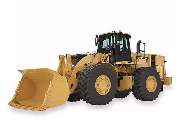
Here we can see a very common use of the wheeled loader.
Next, let’s take a look at some loaders that are used exclusively underground. The amount of clearance available underground can be quite restrictive. While some underground mines will have openings that are approaching 100’ in height, less than 10’ is much more common. The equipment designed to operate in these confined spaces has to be designed quite differently to fit into these spaces and still be capable of doing something useful.
Scoops and LHDs (Load-Haul-Dump)
There are some differences between scoops and LHDs, but for the purpose of this discussion on loaders, we are not going to differentiate between the two other than to note that scoops are more likely to be used strictly for loading ore into an underground mine truck in metal mining, and that they are often used for moving supplies around in underground coal mines.
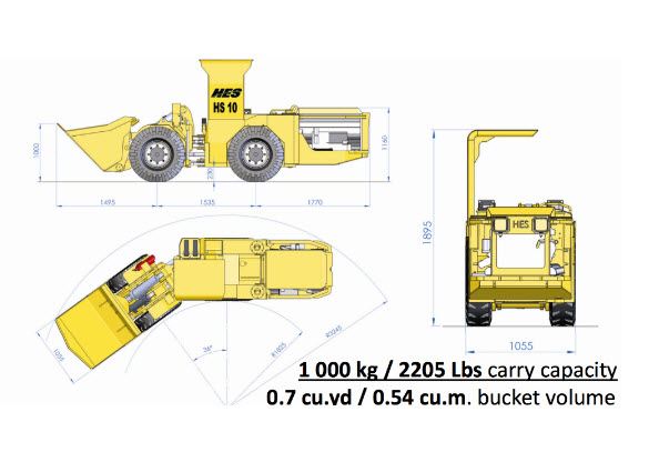
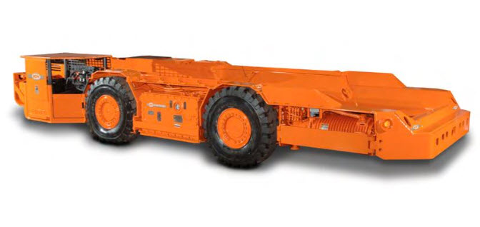
These machines are designed with a low profile to function in confined spaces. Moreover, they are often articulated, i.e., the machine is split into two parts and connected with an articulating joint. This allows the machine to turn and maneuver in tighter spaces. The scoop loader shown here illustrates the concept quite nicely. At less than 3-1/2’ wide, 6’ high, and 16’ long, it would easily fit inside of the bucket of many surface loaders! The bucket capacity of these machines ranges from just under 1 yd3 to 4 or 5 yd3.
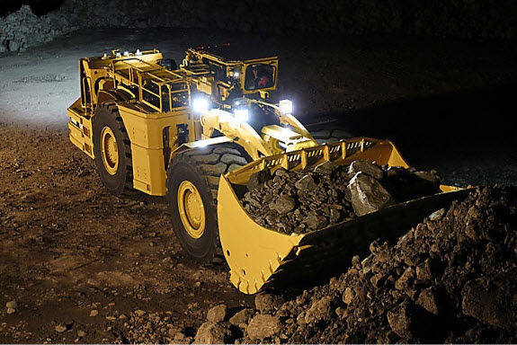
Here is a picture of a typical LHD, which stands for Load-Haul-Dump. These machines are commonly used in underground metal mining and they push into a pile of broken ore (load) and then they haul (transport) their load to a dump point. The haul distances are relatively short – typically less than a 1000’, although this can vary. This LHD is available with bucket capacities ranging from 10 to 15 yd3.
When we talk about the underground metal mining methods, you will see the importance of LHDs in those operations.
This brief introduction to loaders is by no means exhaustive. There are still some legacy devices in use – overshot loaders and slushers, for example, in metal mining. However, here, we have covered the devices that account for virtually all tonnage produced in modern mining systems. This also brings to a close our discussion not only loaders but also ore winning, more or less. Wait a minute, more or less? Well mostly more… however, we have not talked about an important class of ore winning machines known as continuous miners, road headers, and shearers. We’ll do that in the next lesson. For now, we’re now ready to move into materials handling – the last unit operation in the production cycle of drill-blast-load-haul for hard rock or excavate-load-haul for soft rock.
5.1.2: Materials Handling
5.1.2: Materials Handling
Materials handling is concerned with how we move (haul) the mined material out of the mine to the processing plant. Before looking at specific haulage options, we should talk about a few overarching concepts. The first is intermediate haulage.
At the working face, i.e., where the ore is being freed from the deposit, we are going to load the ore into some type of haulage. If we are in a surface mine, it is likely that we’ll load the ore into a truck, which will haul the ore the entire way to the plant, dump it, and then return to the face for another load. If we are in an underground mine, it is likely that the material at the face will be loaded into a haulage vehicle and then transported to an intermediate dumping point. From the intermediate point, a different haulage device will be employed. Sometimes, there could be even another subsequent intermediate device. As an example, assume we have a mine in which LHDs are used to load out the ore at the draw point (face) and transport it to a dump. The dump point is at an ore chute in the rock that funnels the ore to a lower level where it is loaded into rail cars, along with the ore from many other dump points. A train may pull these cars several miles out of the mine and to a processing plant. Or, the train may take the ore to a transfer point at the bottom of the shaft, where the ore will be dumped and transported in large ore skips (buckets) up the shaft to the surface. The choice of a specific type of materials handling is based on optimizing the overall process. Smaller and maneuverable equipment is best suited at the face, whereas larger capacity, but more permanent equipment may be indicated to move the material out of the mine. As we look at different mining methods, this will become even clearer.
Let’s identify the common choices for materials handling, to move material from the face to the plant.
Click here to see a text description.
- Group 1
- LHDs
- shuttle cars
- bridge conveyors
- Group 2
- mine trucks
- haul trucks
- rail
- Group 3
- rail
- haul trucks
- hoists
- hydraulic transport
- belt conveyors
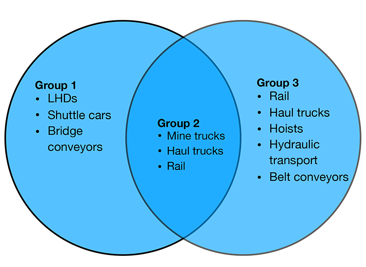
I’ve arranged them into three groups. The equipment in the first group is typically used for short haulage runs from the face to an intermediate dump or transfer point. The equipment in the third group is used to move the material out of the mine and to the plant. The equipment in the second group can fall into Groups I or III. In some instances, the equipment shown in Group II will be used to move the material directly from the face to the plant, whereas in others, it will be used to transfer the ore to an intermediate point. Again, the choice and rationale will become clearer as we learn about the requirements inherent to the different mining methods. Let’s look at the general characteristics of these materials-handling modes. We’ve already discussed LHDs, so let’s begin with shuttle cars.
5.1.2a: Shuttle Cars and Bridge Conveyors
5.1.2a: Shuttle Cars and Bridge Conveyors
Shuttle Cars
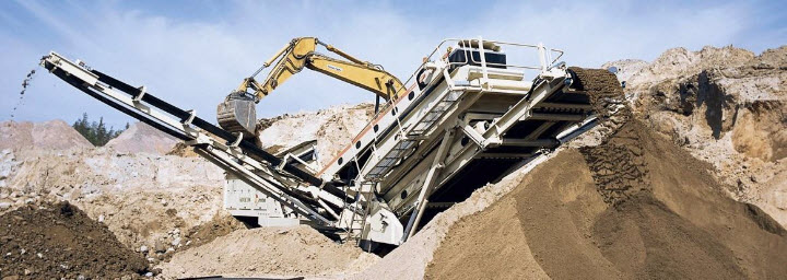
Shuttle cars are a low-profile intermediate haulage option used predominantly in underground coal and some industrial minerals mines. Ore is loaded into the shuttle car at the face, and then it trams a relatively short distance, dumps its load, and returns to repeat the cycle. Shuttle cars are manufactured in different sizes to work in very thin seams of less than 36” to high seams, greater than 72”. The capacity is dependent on the size, but a typical capacity is 6 – 10 tons. The shuttle car normally dumps into a feeder-breaker, which crushes any large lumps and feeds the load onto a conveyor belt. Variations of the shuttle car include ram cars and haulers.
Bridge Conveyors
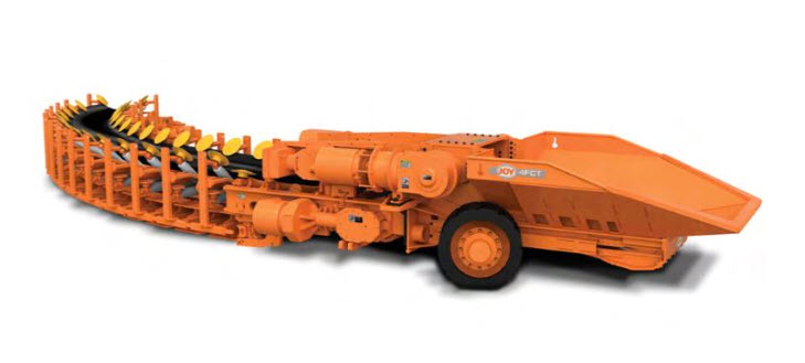
Bridge conveyors are belt conveyors that are designed to move material directly form the face to a final point, e.g., a spoil pile in surface mining, or a transfer to a main conveyor in underground mining. Unlike main-belt conveyors, which are semi-permanent, bridge conveyors are designed to be easily maneuverable, to keep up with the active mining face. Looking at this bridge conveyor, known as a flexible conveyor train, you can see the hopper where ore is loaded. There is a feeder in this hopper that meters the ore onto the rubber conveyor belt. Note that the belt can go around corners. These have found limited application in underground coal and salt mines.
Here is an example of a conveyor being used to transport spoil (overburden) directly from the bucket of an excavator to spoil piles.
5.1.2b: Mine Trucks, Haul Trucks, and Rail (Trains)
5.1.2b: Mine Trucks, Haul Trucks, and Rail (Trains)
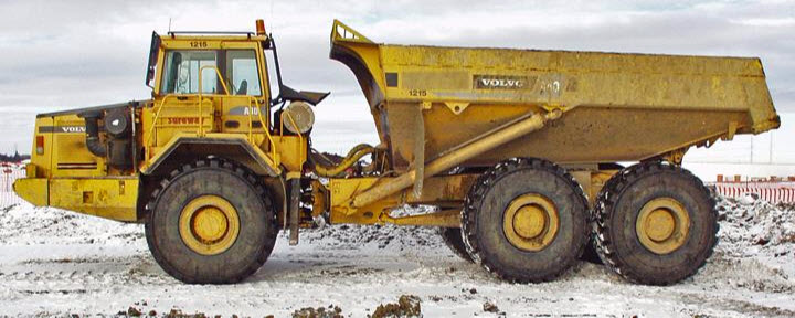
The distinction between haul trucks and mine trucks is subtle but important. Mine trucks are generally designed for underground use in more confined spaces. They will have an articulating joint to allow turning in a tighter radius. The capacity will also be less because of clearance restrictions. Nonetheless, capacities of 15 to 60 tons are common. These mine trucks, as pictured here, are commonly used in underground metal and nonmetal mining, and they are as likely to transport the ore directly from the face to the plant as to transport to an intermediate transfer point.
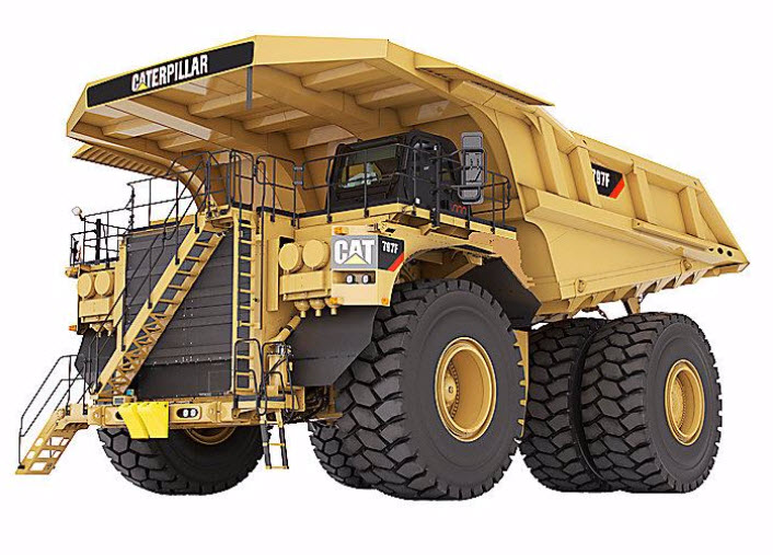
Haul Trucks
Haul trucks are designed to transport larger loads than mine trucks, and in some underground mines where there is sufficient room, you will find haul trucks. For example, in a salt mine where a 90’ thick seam is being removed, you can fit a large truck of 60–100-ton capacity, although, in underground metal/nonmetal mines, a size of fewer than 60 tons would be more common.
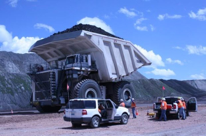
This haul truck holds nearly 450 tons and is in use at a surface coal mine in the Powder River Basin.
Rail (Trains)
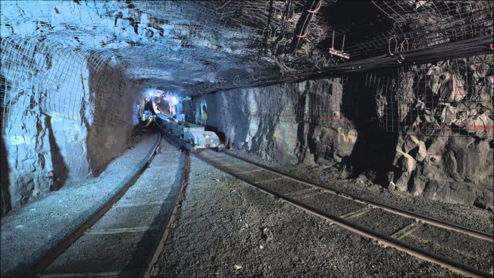
Rail haulage was once very common in underground mines, and even in some surface mines. It has the advantage of being able to transport large loads at a low cost. It has fallen out of favor because it has inherent problems that make it unsuitable for many of today’s high production mining systems. Nonetheless, it is still used. In modern coal mines, for example, rail haulage will often be used to transport equipment and supplies, whereas conveyors will be used to transport the coal. The reasons for this will become evident when we look at batch and continuous operations in the next lesson. Rail can be used as an intermediate form of haulage, or as the means to transport the ore out of the mine to the plant. The locomotives and cars used may be of lower profile, like the one shown here.
5.1.2c: Hoists, Hydraulic Transport, and Belt Conveyors
5.1.2c: Hoists, Hydraulic Transport, and Belt Conveyors
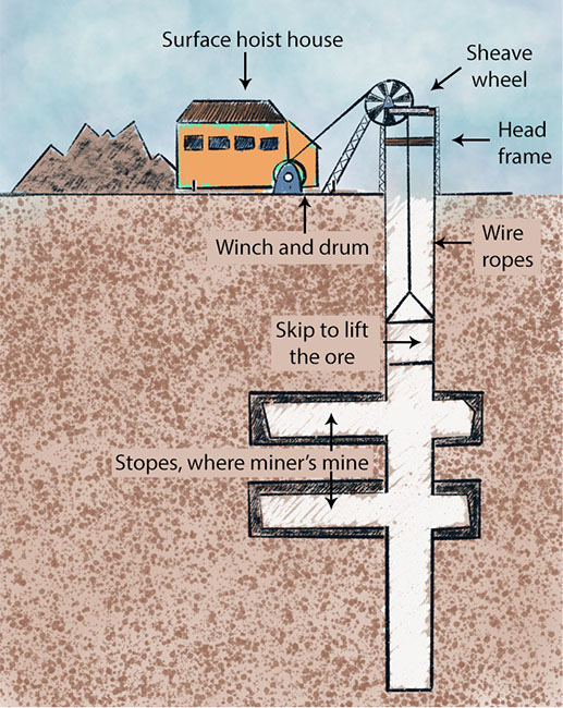
Deep underground mines may be accessible only through a shaft that is sunk from the surface to the working levels of the mine. Not only will all workers and supplies access the mine through the shaft, but also all ore will have to come out of the shaft. This is accomplished by hoisting systems. Three major components of a hoist are the skip, which holds the ore and is attached to the winder on the surface by wire ropes, the headframe and the hoist winder (winch and drum). The headframe supports the sheave wheel over which the wire rope is connected to the skip. As the drums in the surface hoist house wind the rope onto the drum, the skip is pulled to the surface, where it is dumped.
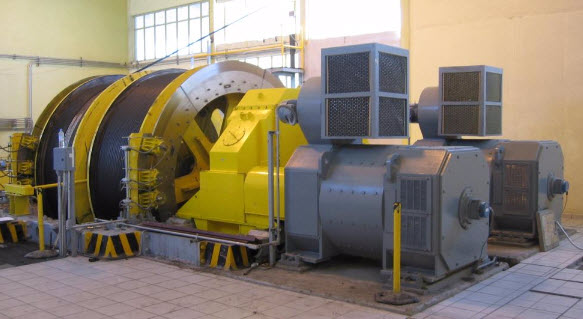
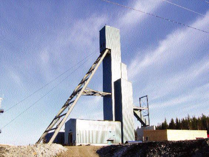
The winder is shown in the first picture below, the bottom headframe in the second, and the bottom dump skip in the third. Often a different type of hoist from the one shown is used, which allows a skip to be connected at the bottom and the top of the shaft so that as the one is being unloaded, the other is being loaded. A skip typically holds up to 50 yd3 of material.
Hydraulic Transport
Hydraulic transport, often known as a slurry transport system, is used in limited circumstances. The ore is mixed with a fluid, e.g., water, and pumped from the mine to the processing plant. It is an energy-intensive system and is best suited to a limited class of ores such as phosphate, which is already mixed with water in the mining process, or other ores obtained from hydraulicking or dredging. The system is straightforward, consisting of high horsepower slurry pumps every few miles and a large diameter pipe, greater than 2’ in diameter.
Belt Conveyors
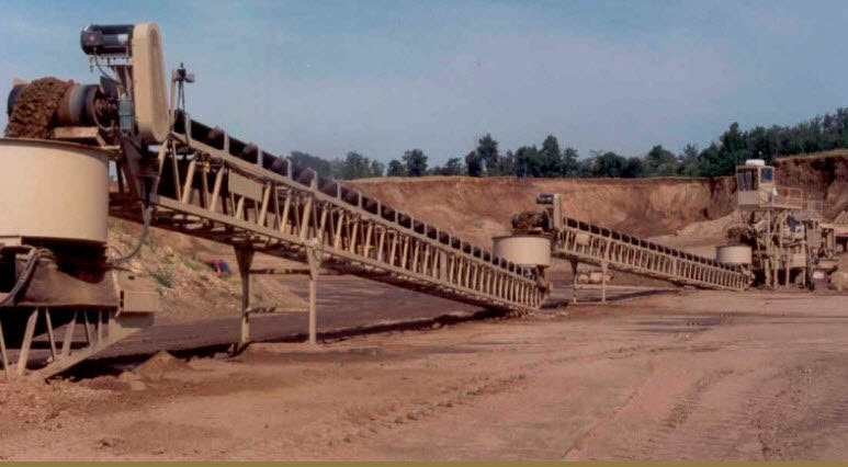
Belt conveyors are the workhorses of modern mines, both surface and underground. The belt conveyor consists of the belt, which is constructed of multiple plys to provide the required strength and wear resistance; the belt is constructed into a closed loop and stretched between a head and tail pulley; the belt is supported with idlers between the head and tail, and they maintain the appropriate trough shape as well as support the weight of the material in the belt. The head pulley is connected to a motor to power the conveyor. These belts range in width from a few feet to more than 8’, and can transport thousands of tons of ore per hour. Although each belt is of limited length based on mechanical constraints, they can be combined into long runs by constructing transfer points to allow one belt to dump onto another. In this fashion, complex networks can be assembled. Here is an example from a surface mine.
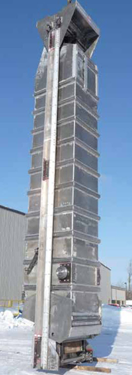
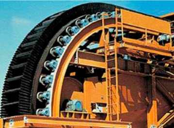
Many years ago, the incline angle of the conveyor was limited by the angle of repose of the ore being conveyed. If this angle was exceeded, the material would begin to slide down the conveyor and would no longer be conveyed upward. Modern designs and significant material improvements now permit belt angles up to 90°, as shown in the second picture.
Lesson 5.1 Summary
Lesson 5.1 Summary
There is, of course, much more that we could say about materials handling systems. Indeed, we have an entire course on their design! For our purposes here, this brief overview will help us to understand the sequence of operations in the mining methods that we will be studying.
Knowledge Check
In Lesson 5.3, we’ll take a look at the difference between batch and continuous operations, and the evolution of the so-called “continuous mining systems.” However, before talking about that topic, we will look at auxiliary operations next.