Lesson 5.2: Auxiliary Operations
Lesson 5.2: Auxiliary Operations
In the last lesson, we learned that the process of exploitation reduces to two fundamental operations: winning and materials handling. Further, we defined the basic production cycle in terms of unit operations, as follows:
Harder Materials: drill, blast, load, and haul
Softer Materials: excavate, load, and haul
I noted that there is one other category of common operations known as auxiliary operations, which support the production cycle and are essential to it. Auxiliary operations are repeated over and over again; and as with the unit operations, the specifics of the auxiliary operations will vary by mining method and the characteristics of the orebody. In the last lesson, I gave a few examples of auxiliary operations, including ground control and electric power.
In this lesson, I want to provide additional information and examples of auxiliary operations, including the equipment used in these operations. The auxiliary operations are not only complementary to the unit operations, but are generally essential to the completion of the mining cycle. As such, it is difficult to say that some are more important than others. So, if we want to see they are all equally important, then I would add that a few of them are first among equals! Those would include ground control, power, and ventilation.
5.2.1: Ground Control
5.2.1: Ground Control
An Overview of the Requirement
One of the more important and defining characteristics of mining engineers is their ability to design structures in earth materials. Few appreciate the incredible challenge this presents. Consider that if we want to design a building, we can go to a handbook and find the exact mechanical properties of our building materials, whether they are steel beams, lumber, or concrete. Important engineering challenges may remain in the design of the building, but at least we know the properties of our building materials.
…not so when we are constructing something in the crust of the earth. Sure, we can conduct lab tests and that is helpful, but significant uncertainty remains throughout the property in many cases. Even when we have a well defined material, a limestone for example, it may have structural defects due to geologic processes that result in fractures, joints, and so on. Once past the hurdle of knowing the properties that we are working with, we have to work with them! That is to say, some of the materials may be “inferior” or “substandard” to use construction terminology. But, in our case, we can return those “inferior” rock structures to the maker, and demand new ones with better properties. And here lies what can be a daily challenge for the mining engineer: maintaining a stable and safe rock mass to allow mining of the valuable commodity.
Whether we are designing and operating a surface or underground mine, this will be a challenge of varying degrees. In the surface mine, we are concerned with a failure of the slope or the highwall. If it is too high or too steep or if there has been an influx of groundwater, or… we can have a failure. The failure could kill all of the workers in the area, destroy or bury the equipment, and result in costly production delays. In an underground mine, we develop a series of openings to access and exploit the deposit. If any of those openings cave in, it can have disastrous consequences for the miners and the overall viability of the operation. The art and science of safely designing structures in the earth is captured in the term ground control. The coursework in engineering mechanics, strength of materials, and rock mechanics will give you a solid theoretical foundation, and then courses in ground control along with years of experience will enable you to succeed in this endeavor.
I think you are beginning to appreciate the importance of this auxiliary operation, which is an intimate companion with the unit operations of the production cycle. Here in this course, we’ll talk about how the ground conditions affect the mining methods and the sequence of operations, and some of the practices that are used to “control the ground” to prevent unwanted and unexpected failures.
Ground control is achieved in part through the design of the structures. For example, the engineer will design spans that won’t fail or determine the angle of the highwall to reduce the risk of a slope failure. We’ll leave the design component of ground control to other courses. Operationally, after the design, ground control is achieved in part through the use of various technologies. Uses of these technologies are an ongoing part of the production cycle, and as such are of special interest in this lesson.
Cyclical Practices
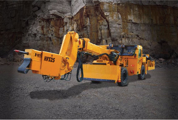
After drilling and blasting, the integrity of the surrounding ground will be inspected. This will happen prior to loading to ensure that miners engaged in the loading operation are not put in danger. This check is imperative in underground mining, and in many surface mining operations. There may be pieces of rock that have cracked but hung up, and they may fail without warning. Or there may be loose pieces that could fall. Thus, the inspection will be the prelude to scaling or barring, i.e. the act of knocking these pieces free. In a low seam mine, with minimal need for scaling, this may be accomplished with miners using a steel bar with a chiseled edge. When it is impossible to reach the area that needs scaling, then equipment will be used. Here is a scaler that is found in metal/nonmetal mines; and primarily but not exclusively in underground mines. It has a telescoping boom to reach high places and a pneumatic hammer to release any worrisome pieces of rock. The operator remains inside the cab, which provides protection from falling material. Notice also the dozer blade on the front. It is used to push a fallen material out of the way.
Ok, so this inspection and scaling represents the first auxiliary operation.
Once the area has been scaled, it will be safe to bring in equipment for loading and hauling in some mines – mines with competent rock that is not going to cave. In some mines, it is necessary to take further steps to improve the opening to ensure that the rock strata is not going to fall onto the miners, and this must be done before miners work in the freshly mined space. If additional reinforcement of the rock is required, then that will be the second auxiliary operation.
We’ll take a look at some of the equipment used to reinforce the rock, but first, a quick tutorial on the options for adding additional support to the ground.
5.2.2: Active and Passive Ground Support
5.2.2: Active and Passive Ground Support
Ground support can be active or passive. If we take actions that actually increase the strength of the rock, then we are providing active support. On the other hand, if we do nothing to increase the strength, but instead we take an action to prevent the rock mass from falling, then we are providing passive support. There are valid applications of both categories of support. Let’s look at an example. Actually, this is a really important example!
The rock strata overlying a tabular deposit are often somewhat weak. They may consist of relatively thin layers of a weak rock. These layers, which may be a few inches to a few feet in thickness, may also have partings between them. These partings may be very thin, and very weak. Now, what is going to happen when we remove the ore from underneath the overlying rock mass that I just described?
Did you ever have a long bookshelf made of wood – wood that is not very thick? What happened when you place a full load of books on the shelf? It begins to sag in the middle, right? It may not have happened immediately, but over time, it sags in the middle. A similar mechanism is at play in the mine strata of our example. All of the weight of the overlying rock layers is pushing down. You removed the ore from underneath the strata, so you now have a long unsupported span of relatively weak rock layers. The rock layers begin to sag, and before long the lowest layer will separate from the others, and fail. When it fails, it will break apart and fall to the ground. Now, the layer immediately above the one that just failed will sag, and it too will fail. This will continue until the rock mass reaches some equilibrium. This is an unacceptable outcome! We’ll never make any money at this mining business if we can’t support the openings that we create! So, you must prevent the initial failure. What are your options?
As with the bookshelf, you could place a support in the middle of the span to support the load and prevent sagging. In our mine, we could set a timber post into place, and it would prevent the failure. This is an example of a passive support. Placing timber posts, steel arches, and so on is a time-honored means of supporting the rock and preventing failures. There are some drawbacks, however. If we’re mining a 6’ thick coal seam, we can set a 6’ post. What if we are mining a 60’ seam of limestone? Finding, handling, and placing a 60’post would be a supremely daunting task, and clearly not practical! Even when it would be easy to set a post, there can be unacceptable drawbacks to the practice.
Let’s think about a basketball arena like Bryce Jordan Center. The roof of that building spans a large area, and that roof needs to be supported. Assuming that we can obtain timber posts of sufficient length, why not set them across the width of the building, perhaps every 20’ or so to support the roof? For starters, it would make for an interesting new twist to the game of basketball as the players dodged the posts on their way to the basket! Again, not very practical, and that is the drawback in the mine as well. Instead of basketball players, we have large equipment moving around and between the working areas. Thus, in many locations, this kind of passive support is inconsistent with production needs. While passive support is an appropriate control strategy in many instances, we need an alternative for when it is not.
Roof Bolts
One of the most prevalent and effective means of providing ground support is an active support known as a roof or rock bolt. Remember the failure in the layered strata of our example mine? What if we were to clamp several of those weak layers together, forming a “laminated beam”? Beams are very strong, and, indeed, by clamping these layers together, we have strengthened the rock mass, and it will be able to support the weight on it without failing. Many of you may have seen laminated beams used in building construction. Several layers of thin and relatively weak plywood are glued together, and the result is beam with superior properties to a solid piece of wood of the same thickness.
In our case, we can’t access both sides of the rock mass to clamp the layers together, as is the case when they fabricate laminated wooden beams. Instead, we use a rock bolt, as illustrated in this diagram.
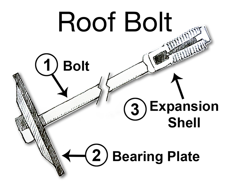
It works as follows. A hole is drilled into the rock mass that is to be supported. Next, the roof bolt is inserted into the hole. Then the bolt head is rotated, which causes the expansion shell to expand into the surrounding rock, locking it in place, and as the bolt rotates, it draws in the bearing plate. As a result, the layers between the expansion shell and the bearing plate are compressed tightly together, forming a beam. For this to work, the expansion shell must be anchored in competent rock. Sometimes, this can be done over 4’ and other times, 6’ or more. The length of the bolt is chosen with this in mind. The diameter of the bolt, which is between ½ - 1”, is based on the required tensile strength of the bolt, which is determined by calculating the weight of overlying rock that each bolt will have to support. In the future, you will learn how to size rock bolts. At this time, the takeaway message is:
- bolting is an active support because it is increasing the strength of the rock mass to prevent failure by clamping weak layers together to form a strong beam; and
- bolting is the most prevalent means of ground control in the majority of underground mines, and also in certain surface mines.
Under difficult conditions, we can place a skinny bag of resin, i.e., a strong glue, into the hole with the bolt; and then, as the bolt spins while it is being tightened, the bag will break and the resin will be mixed and will completely fill the hole around the bolt. Moreover, this resin will plug cracks and fractures in the rock in the immediate vicinity to further enhance the bolt’s holding power.
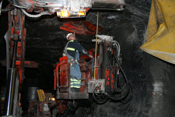
Here is a picture of roof bolting machine, commonly known as roof bolter or simply, a bolter. If you look closely, you will see the drill in front of the operator. Notice the attachment point to the machine at the bottom, i.e., the chuck. As the hole is drilled, that chuck assembly will move up towards the collar of the hole. After the hole is drilled, the operator will place a bolt in the chuck, insert it into the hole, and tighten it. The machine has plenty of space to store a supply of bolts along with the drill tools. You will also notice hydraulic canopies pressing into the top or “roof” of the mine opening. Those are passive supports to ensure that the top does not fall down while the bolter operator is installing the roof bolts.
In so-called large opening mines, where the distance between the bottom and top of the mine opening might be 20 – 30’ or more, a slightly different configuration is required, as shown here. The operator would stand in the “cherry picker basket" and operate the drill and bolter.
Cable Bolts
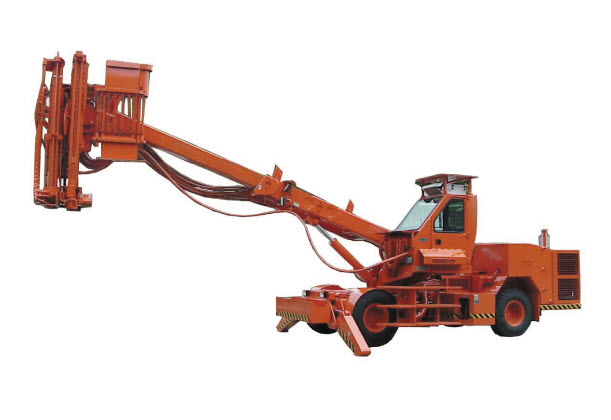
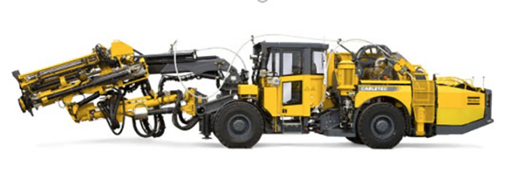
Sometimes, we need a bolt that is much longer than 4 – 6’. Remember, I said that for the bolt to achieve its purpose, the anchor must be in a competent rock layer. What if that layer is 15’, or 50’ or even 100’ above the opening? A bolt of such lengths would be impractical. Instead, we use a cable bolt. A reel of specially constructed steel cable is stored on a cable-bolting machine. A hole of the required length is drilled, an anchor shell is attached to the end of the cable, and it is fed to the end of the hole. An anchor plate and tensioning bolt is affixed to the end, and it is tensioned in some fashion as a traditional rock bolt. One difference, however, is that concrete grout will be pumped into the hole as well. Here is an example of a cable bolter. If you look closely, you can see the cable routed from the spool on the rear of the machine, up over the machine, and to the front where it will be inserted into the hole. The carriage housing the drill steel and the drill are also visible at the front of the machine.
Shotcrete
Shotcrete is another active support of note. Pillars of rock or ore are often left standing to help support the overlying strata, and only the ore between the pillars is recovered. The pillars can be under a lot of stress, and in some cases will begin to fail. The outer layers tend to crack and spall off, until the pillar is much skinnier and more likely to fail. The spalling of the outer layers can also present an immediate safety problem. One means of active support is to spray a Shotcrete onto the pillar. The Shotcrete may be cement or polymer mix, and fibers of various materials may be embedded in the mix. Thicknesses of an inch or more would be typical. Once the Shotcrete has dried, or really cured, it is quite strong and provides a confinement stress on the pillar. Sometimes the top surface of the span will be shotcreted as well.
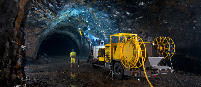
Here is a picture of a shotcrete operation in progress. You may be able to see the nozzle at the end of the boom, the mixing tank, and the dry feed hopper, and water line on the equipment. The other line is an electric power cable. The hose and cable reels provide sufficient mobility to the machine to allow it to move freely among working places, at least until the limit of the hose and cable are reached. Then, it will be necessary to advance the electrical and water supplies. Advancing utilities, such as electric power and water, is another important auxiliary operation that we will discuss shortly.
We’ve covered the majority of the ground control technologies with this brief introduction to active supports such as roof bolts, cable bolts, and shotcrete; and passive supports such as timber or steel posts and arches. There are others, but this group is illustrative. There is one more ground control technique that deserves a brief mention before we move on to other auxiliary operations, and that is backfilling.
Backfilling
Backfilling is the process of adding support to a mined out area by filling it with backfill, i.e., waste rock, tailings, or a mixture of cement and tailings or waste rock. As you might suspect, the time and cost to backfill is very expensive. Nonetheless, it is a part of the cut and fill mining method, in which we routinely mine a slice of ore, backfill it, and mine out the next slice, and so on. We’ll talk more about backfilling when we discuss this mining method. For now, you should simply be aware of backfilling as another ground control practice.
Also, I want to be clear that while the ground control challenge in underground mining is generally far more complicated than in surface mining, ground control practices including inspection and scaling are part of surface mining, and the use of rock bolts is part of some surface operations.
After this brief tutorial of ground control, you’ve probably forgotten how we got started on this discussion in the first place! Ground control is a critical auxiliary operation, and although we usually speak generally of ground control, in total, we’ve now seen that there are three components: inspection, scaling and installing ground support. Depending on the mining method and the competency of the rock, the activities associated with ground control may occur at differing time points in the production cycle.
5.2.3: Electrical Systems
5.2.3: Electrical Systems
The power sources for mining equipment are compressed air, diesel, and electric. Most mining equipment today is powered with either diesel or electric. Diesel provides more mobility because there is no need to be tethered to an electrical cable. On the other hand, the exhaust from a diesel engine creates challenges when used in a confined space, like an underground mine, and it requires a high level of regular and sophisticated maintenance. Electric has certain inherent advantages including the ability to provide a lot of power in a small space and no toxic emissions at the machine. Large equipment, such as draglines and shovels, as well as continuous miners, is usually electric. Diesel is favored for haul trucks because of the need to be untethered.
Nearly fifty years ago, there was an effort to replace electrically powered equipment with diesel engines. Eliminating the delays associated with the tether, as well as delays associated with inevitable failures of the tethers (cables) was easy to justify; and particularly so for mobile materials handling equipment. In recent years, the air quality issues associated with diesel particulate matter and noxious gases from the engine exhaust have caused some operators to transition back to electric equipment.
I should mention battery-powered equipment, given that today we are seeing more and more battery-powered vehicles on the highways. With battery power, the tether, i.e., the cable, is eliminated, and there aren’t the drawbacks associated with diesel engines. Unfortunately, it is difficult to pack sufficient energy into a battery pack to replace the “workhorses” of hauling ore and rock. Consequently, battery-powered equipment is used for utility vehicles, such as personnel carriers or scoops for hauling supplies.
The machinery associated with production will move throughout the mine over the mine life, and as this equipment makes its way through the deposit, it will be necessary to move the electrical power system along with it. Depending on the mining method, we may need to move power every few shifts, or in other cases, only every few months. Many of you have some familiarity with power systems found in towns – the substations, power lines, and so on. Can you imagine having to move and advance such a power system on a frequent basis? In many mining methods, that is all part of a day’s work! Of course, we’ve taken steps to make it more manageable. The substations and other equipment that have to be moved are mounted on skids, crawlers, or rubber tires to facilitate movement. Couplers are used to connect and disconnect components and cables. It’s manageable!
Of course, there are other electrical loads, some of which must be moved periodically, and others that are stationary and semi-permanent. These loads would include pumps, conveyors, and illumination. Even if the mining machinery is all diesel powered, it is likely that there would be other electrical loads that must be powered. Therefore, providing electrical power will be a necessary auxiliary operation for most mining methods used in surface and underground mining.
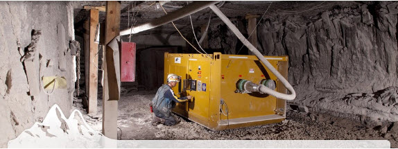
Here is a picture of a skid-mounted power center for use in an underground mine. You can see the high voltage cable going into the box. Inside, there is a transformer to reduce the distribution voltage, typically 4.16 to 15 kV, to the level required by the machinery, typically 480 to 995 V. On the other side of this box, outside of our view, there are couplers to connect the various loads. Protective devices for each outgoing circuit are built into the power center.
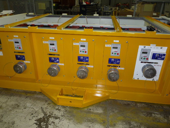
Here is a picture of a similar power center, which has just been built. Here, you can get a better view of each outgoing circuit. Each cable-connected load plugs into one of these circuits. The lid of the power center is removed only for maintenance purposes.
You might see a load center like the one in the following picture in a surface mine. Essentially, a shipping container has been mounted on a skid, and the required electrical components have been assembled inside the container. I’ve seen power centers in surface mines that have been built on railroad cars and old tractor-trailer beds, among others!
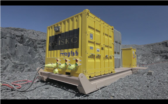
As I mentioned earlier, these power centers must be advanced as mining progresses. Often a “power move” will require adding additional high-voltage cable, or in some surface mines, adding additional poles and overhead lines. Some mining methods are more “electric-intensive” than others, and that also varies by commodity. Room and pillar mines in coal, salt, or trona, for example, are very power intensive, requiring significant infrastructure and frequent moves. Others, such as room and pillar mining in limestone or cut and fill mining in gold, require less electrical infrastructure and few moves. Nonetheless, providing safe, reliable, and timely power is a critical auxiliary operation in most mines.
5.2.4: Ventilation
5.2.4: Ventilation
Fresh air is required to provide oxygen and to carry away carbon dioxide. Large quantities of air are often required to dilute, render harmless, and carry-away dangerous dusts and gases. Methane is an explosive gas associated with coal deposits, among others. Sufficient air must be coursed through the coal mine to keep the methane concentration well below the lower explosive limit. Hydrogen sulfide, a deadly gas, forms under certain conditions in underground metal mines and must be diluted to render it harmless. Carbon monoxide and oxides of nitrogen are produced during blasting, and these toxic gases must be diluted and carried away before miners return to continue the production cycle. The concentration of respirable silica dust, i.e., dust small enough to become trapped in the lungs, is produced during mining and can lead to fatal lung diseases when inhaled over years of work. Accordingly, the allowable concentration of respirable dusts is heavily regulated and controlled, and providing sufficient air to carry away these dusts is important. We could go on with the examples, but you get the idea!
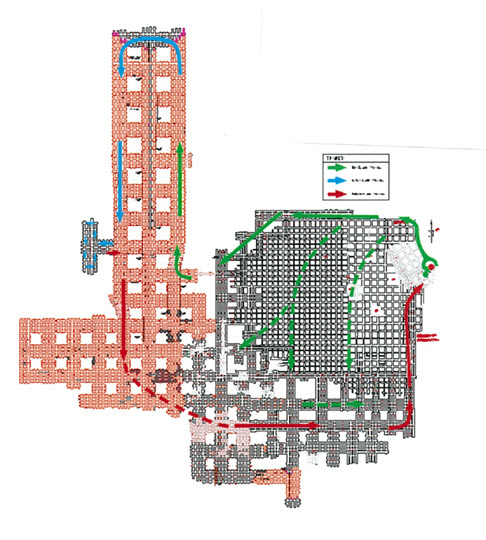
It is easy to understand the need to provide large quantities of air, sometimes on the order of several hundred thousand cubic feet per minute! It is not so easy to control that air, to get the right amounts to the different parts of the mine, and then to move the “dirty air” to outside of the mine. It takes significant engineering, and many control devices, to achieve the intended outcome. If you look, for example, at this plan view of a mine, below, you can see the many passageways. It resembles the streets and avenues of a city. Now imagine that you have one or two entry points for fresh air, as provided by fans, and you have a few exit points where the exhaust air is ventilated to the outside. All that you have to do is to make sure that the proper quantities are flowing in each of the “streets” and “avenues.” Further, you have to do this on an ongoing basis, since the layout of the mine changes from day-to-day as mining advances. No small feat…! Depending on the mining plan, you can build stoppings, i.e., solid barriers to divert air, you can hang curtains to divert air, you can install and adjust regulators to control pressure drops and the attendant airflows, and you move auxiliary fans and tubing to further direct airflows to where they are needed.
When we looked at ground control, we identified the importance of inspection, as the first step in that auxiliary operation. Similarly, with ventilation, there is a “check” that occurs as a prerequisite to certain unit operations. Gas measurements may be required as well as air quantity determinations. It may be necessary to adjust the ventilation system as a result of these measurements or to change the production plans until adequate ventilation can be provided.
Our discussion has focused on ventilating underground mines, and indeed that’s where most of the action is to be found. Interestingly, surface mines occasionally experience challenging ventilation problems. Some open pit mines, for example, are deep enough that temperature inversions can occur, in which air in the pit is trapped by a cooler and heavy layer of air near the top of the pit. The diesel fumes from the heavy equipment operating down in the lower levels of the pit can build up to dangerous levels. Utilizing artificial ventilation in this circumstance, whether the wind induced from the blades of a helicopter hovering over the pit or large axial vane fans, is essential to protecting the health of the miners and ensuring that production can continue.
Ventilation, as with ground control, is a crucial auxiliary operation.
5.2.5: Maintenance
5.2.5: Maintenance
The level of maintenance required to keep the equipment operating properly and safely varies by the mining method and the particular equipment in use. Usually, the idea is to minimize breakdowns during a production shift and the need for emergency maintenance. Instead, preventive maintenance is practiced to reduce failures, and scheduled maintenance is planned for nonproduction shifts. In some mines, there will be two eight-hour production shifts followed by an eight-hour maintenance shift every day. In other mines, there will be two ten-hour production shifts, followed by a four-hour maintenance shift. And in yet other mines, a week of production will be followed with a weekend of maintenance.
The value of a minute is often underestimated by those just learning about the industry. Given the capital cost of mining equipment, and the cost of labor and so forth, a delay can easily cost hundreds of dollars per minute and exceed a thousand dollars a minute in certain circumstances. As such, maintenance is a critical auxiliary operation.
There is an important metric that is used to keep track of how well the mine is doing with its maintenance. The metric is known as availability, which is defined as the amount of time that the equipment was usable divided by the amount of time that we had planned to use it. For example, suppose that we planned to install roof bolts for six hours yesterday. A hydraulic hose ruptured, and it took 30 minutes to obtain and replace the hose. The availability of the roof bolter yesterday is: Instinctively you may feel that this is a pretty good number. After all, if it were an exam, you would have gotten an “A”! Let’s examine this a bit more closely.
If we have a production system, we need all pieces of equipment functioning. Otherwise, a delay in one piece, like the roof bolter, will prevent other equipment from moving into that workplace. As a result, the other equipment will be delayed as well. Mathematically it can be shown that the availability of a system of equipment is equal to the product of the individual availabilities of the machines. Let’s imagine that we have the following group of equipment in our production system, along with the availabilities as shown. What is the availability of this production face?
- Jumbo drill 90%
- Scaler 96%
- Rock Bolter 92%
- Wheeled loader 92%
- Mine truck #1 88%
- Mine truck #2 91%
- Feeder-breaker 98%
- Conveyor system 94%
Can you believe it? 54%! In other words, at this production face, they are mining only half the shift! And if you really want to have an anxiety attack, let me tell you that we haven’t accounted for other mining delays – unexpected rock falls or an explosives misfire, for example! We can drop down close to 40% overall availability if we aren’t careful. Clearly, there’s room for improvement – better engineering, better maintenance, and so on!
Lesson 5.2 Summary
Lesson 5.2 Summary
In this lesson, we’ve learned about auxiliary operations and how they fit into the mining cycle. We’ve also gained important insights into ground control, ventilation, and maintenance operations. We’ll see how these auxiliary operations combine with the unit operations to complete a cycle of operations for the different mining methods.