Lesson 5.3: The Quest for Continuous
Lesson 5.3: The Quest for Continuous
Near the end of Lesson 5.2, I introduced you to the concept of availability in the context of equipment maintenance and unexpected breakdowns of equipment. We saw that even a seemingly high availability in the 90s for the equipment could result in a shockingly low availability for the overall system. In our example, the availability at that production face was barely over 50%! We focused our discussion on delays created by equipment that was out of service due to a breakdown. The same concept can be applied to other, non-maintenance delays. For the purpose of this discussion, assume that we have the following scenario:
An underground limestone has eight different working faces, but normally only works five of those faces in a given shift. The sequence of operations is:
- Five different working faces were shot (blasted) at the end of the shift yesterday.
- These faces are inspected to ensure that it is safe to load out the blasted ore.
- Loader #1 trams to Working Face A, and waits for Haul Truck #1. Loader #1 begins to load the pile into Haul Truck #1. It takes an average of 75 seconds to load and dump one-bucket load into the truck, and it takes 4-bucket loads to fill the truck.
- Truck #1 trams to the dump point, and it takes an average of 12 minutes to make the trip, dump, and return to the working face.
- Truck #2 was waiting nearby, and maneuvers into position at Working Face A as soon as Truck #1 departs. The loading cycle begins again.
- Truck #3 arrives and waits to maneuver into position as soon as Truck #2 departs.
- Working Face A will be loaded out, after three truckloads, and Loader #1 will move to the next working face.
- Scaler #1 trams to Working Face A, and scales the roof. This takes 45 min. on average.
- Bolter #2 trams to Working Face A, and installs 8 rock bolts. This takes 35 min on average.
- Drill #1 trams to Working Face A, and drills blast holes. It takes 2 hr. on average to set up and drill the pattern.
- The blaster(s) will load the holes. This takes an average of 1 hr. All faces will be loaded, but not shot until the end of the shift.
Finally, let’s assume that we’ve engineered our system perfectly. The equipment moving in and out of each face, and among the faces, resembles a beautiful symphony. All of the pieces come together at exactly the right time for the right duration. It’s a sight to behold! And if you believe this, you probably believe in the Easter Bunny and Santa Claus!
But why wouldn’t or couldn’t this be true? To use yet another metaphor, why can’t it operate like a well-oiled machine?
In a word –variability: the normal variations associated with each operation or piece of equipment. Consider the following list of normal variations:
- The pile of shot rock is compacted, and the loader operator has difficulty loading the bucket in one pass.
- The operator for Haul Truck #2 is not feeling well, is taking more time than usual to make the round trip back to the face, and is delayed in arriving by four minutes. The loader operator is idled until the truck arrives.
- Ground water inflow from an overnight storm has washed out part of the haul road, increasing the travel time for the haul trucks by 20%.
- Difficult ground conditions required substantially more time to scale the working face, which idled the bolter operator.
Honestly, we could go on and on with delays that have nothing to do with equipment maintenance. So, how do we deal with this? We apply industrial engineering techniques: we conduct time studies and develop statistical distributions of the times that it takes to conduct all the specific tasks for each machine. We study and document delays, and of course we attempt to correct the situations underlying the delays. However, our goal is to run production simulations.
Once we know something about the statistical behavior of the unit and auxiliary operations, we can execute Monte Carlo simulations for example, and we can study various options. We can add a truck or increase the size of the loader, for example, and predict how this will affect our production and productivity. We examine the sensitivity of the result for various parameters. For example, we could identify the piece of equipment whose availability has the greatest impact on production. Armed with this information, we can consider improvements to the system, and we can “test” the improvement for making an investment in time or money.
Before continuing with this discussion on production simulations, I want to explain the difference between two words that we just used: production and productivity. Both are important metrics, but the terms are not interchangeable. Production is the amount of material that we have mined. If we say that we mined 20,000 raw tons yesterday, it means that is the tonnage of rock and ore that went out of the mine to the plant. If we say that our production was 15,000 clean tons, we mean that we produced 15,000 tons for sale. Productivity on the other hand, is indicating how efficiently we mine with our labor force. If we required 12 people working for two shifts to produce those 20,000 tons, then our productivity would be 833 tons per man-shift. It’s important to remember this difference. Ok, now back to our discussion on the production simulations.
There is a fundamental weakness in typical production systems that these simulations highlight. As the number of individual operations in a sequence increases, so does the likelihood of more delays. This is intuitive: as you increase the number of people and pieces of equipment required to complete a cycle, you are more likely to experience a delay, whether it is an equipment breakdown or other factor. A practical consequence of this inherent characteristic of production systems is the quest to reduce the number of operations and/or pieces of equipment required to complete a cycle.
As a good example, let’s consider a conventional cycle in an underground coal mine. The following equipment is required:
- Drill: to drill holes for explosives.
- Cutting bar: to cut a kerf at the bottom of the coal face, which serves to create a free face (this improves the performance of the blast).
- Loading machine: to load the blasted coal into shuttle cars.
- Shuttle cars (2): to transport the coal to an intermediate dumping point.
- Roof bolter: to place bolts into the newly exposed roof.
The sequence of operation is in the order of this list. I have not listed the loading of the explosives, nor have I shown that a gas check is required prior to each operation and ventilation curtains will need to be advanced. These are of no consequence for the purpose of this discussion.
In addition to the time required to perform the indicated operation, there is a significant amount of time in the place change, i.e., when the piece of equipment leaves one face, travels to another, and then sets up to begin work at the next face. In this example, the production simulations highlighted what miners knew from experience: the place changes and other delays associated with all this equipment were “killing” production. The solution? Let’s eliminate some of these pieces of equipment and the associated place changes. How? The development of a new piece of technology: the continuous miner.
5.3.1: The Continuous Mining Machine
5.3.1: The Continuous Mining Machine
A picture is worth a thousand words… so, let’s look at the front of a continuous miner. The cutting drum is about 2’ in diameter and perhaps 12’ wide. It is laced with carbide cutting bits, and the drum rotates at about 1 revolution per second. The cutting head is sumped into the top of the seam, and then the drum is pulled down, which is known as shearing. The sump and shear is completed in well under a minute and then repeated. The cut coal drops to the floor, where it is scooped into the belly of the machine. Look at the base of the machine – it sort of resembles a dustpan. There are two gathering arms, which move to pull the cut coal into the center of the machine.
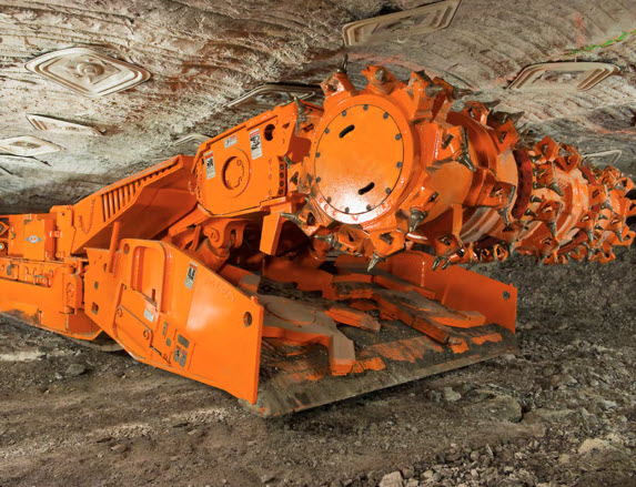
Let’s look at the next picture to understand what happens to the coal.
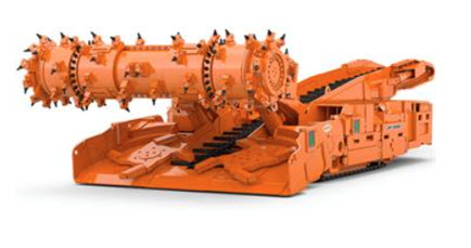
Here you can see it more clearly. The gathering arms pull the coal onto a chain conveyor, which runs the length of the machine. The chain conveyor consists of a metal trough and metal flight bars that are attached to a chain. The flight bars, which are painted black in this picture, are pulled along the metal “pan,” or trough, by the chain. In this manner, the mined material is conveyed to the rear of the machine. The rear of the machine is known as the tail or tailpiece, and it can swing over a limited arc. The tailpiece is positioned over a waiting shuttle car, and the mined coal is fed into the shuttle car. The continuous miner will continue advancing forward with the sump-shear cycles until there is a reason to stop the advance. In U.S. coal mines, the forward advance is limited by a few factors: the need to ventilate the face to maintain safe methane levels and the need to install roof bolts to prevent roof failure. Further, by law, no miners can work under unsupported roof, which will limit the amount of advance. Once the maximum advance has been achieved, the machine will be trammed back out of the cut and moved to a new face.
All right, let’s stop and catch our breath! What have we accomplished with this innovation known as the continuous miner? We’ve replaced drilling, kerf cutting, blasting, and loading with one machine, thereby reducing the number of pieces of equipment, the number of miners, and importantly, the delays. We’ve achieved a remarkable gain in both production and productivity. So much so that conventional mining of coal is no longer practiced in this country. Of course, when you make these improvements, you then expose the next “weakest link” in the system. Based on what we’ve talked about, you probably have an inkling of the weak links. Take a guess!
Many of you have probably zeroed in on the shuttle car -- when the shuttle car is filled it trams to the section dump point and another shuttle car maneuvers into position. In the time that it takes for the full car to leave, and the waiting car to maneuver into position, the continuous miner is idled. That’s a delay that is going to adversely impact our “numbers”, i.e., production and productivity. We’re going to talk more about these haulage bottlenecks shortly, but as it turns out, this is a tough one to fix. There is another weak link, which some of you have undoubtedly spotted: the need to limit the continuous miner’s advance so that the roof can be bolted and ventilation can be extended.
Allow me to introduce you to the Miner-Bolter. It took a number of years to work out the kinks, but today these machines work well. There are different configurations, but the principle is the same: incorporate the bolter into the miner. A bolter operator stands on the platform immediately behind the bolter carriage on both sides of the machine. While the cutting drum is cutting coal, the bolter operators are drilling holes and installing bolts. There is a linked platform to allow the bolters to remain stationary while the cutting head is advancing forward.
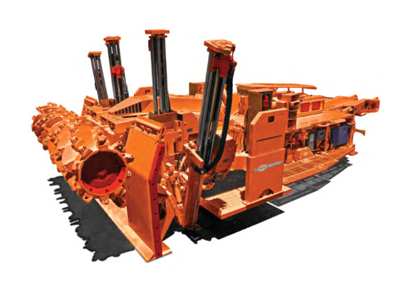
Hydraulic canopies are essential to protect the bolter operators while they are drilling and bolting. The canopies are not extended in this picture, but in the next photo they are, giving you a clearer view.
Typically, there will be a ventilation tube, on the order of 24” in diameter, hung near the roof against the side rib. This tubing will be extended as the continuous miner advances forward, providing the air needed to sweep the face and remove dust and gas.
Although remarkable gains have been achieved, there remains the weak link with the shuttle cars. In fact, there are a couple of options that can be considered. Before taking up this topic, however, I want to say a few more things about these continuous miners.
5.3.2: Continuous Miners for Noncoal Applications
5.3.2: Continuous Miners for Noncoal Applications
The impetus for developing the continuous miner came from the coal mines, but their application has grown beyond coal. The motivation for using them in noncoal mines is the same: eliminate delays wherever possible. In the case of the metal/nonmetal mines, the desire is to eliminate the discrete unit operations of drilling, blasting, and loading, along with the attendant delays. Unfortunately, there is a practical limitation that cannot be overcome in many cases. It is the hardness of the ore. The carbide cutting bits must be able to penetrate and fracture the ore, and do so with some speed and without destroying the bits in a short period of time. The limit is currently a compressive strength of around 80 MPa. This means, for example, that coal, salt, trona, potash, and some copper deposits are suitable, whereas most limestone and lead/zinc deposits are not. Pushing that limit ever higher is the goal of researchers, manufacturers, and the mining companies.
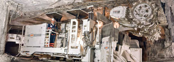
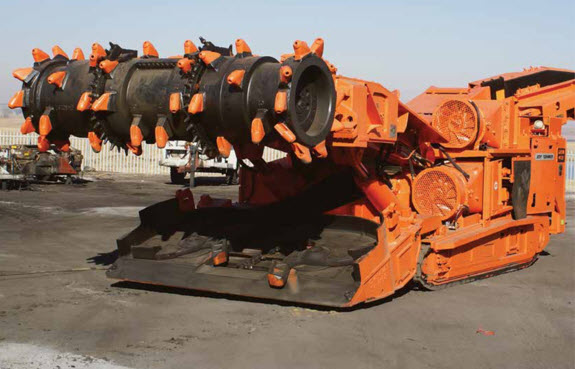
The structure and appearance of the continuous miner will change somewhat for those machines designed for use in harder rock deposits. The miner shown in the picture below looks similar to the one designed for operation in a coal mine, but there are a few subtle and important differences. The size of the machine reflects the thicker deposit in which this machine will be used, the structure is reinforced, and the lacing pattern of the bits is different – larger but fewer bits to concentrate the available energy to achieve fragmentation of the harder rock.
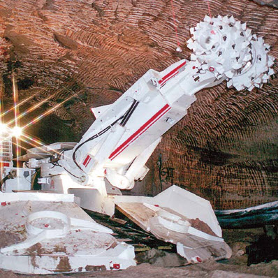
As the hardness of the rock increases, the cutting head will become much smaller, but for the same reason – concentrate more energy into a small area of the rock. Look at what’s happened to the size of the cutting head on this machine. The arm, on which the cutting head is mounted, has the ability to swing and extend. Note the bit marks in the top of the deposit. This configuration of continuous miner is often known as a roadheader, which is based on its European heritage and its use in driving gateroads. Also, take note of the size of the gathering pan and the two gathering arms.
With this overview of continuous miners behind us, we can now return to this question of the shuttle car, and what to do about the inherent delay. Well, it turns out that this is really part of a larger and age-old problem: batch versus continuous haulage.
5.3.3: Batch versus Continuous Haulage
5.3.3: Batch versus Continuous Haulage
Batch haulage is the term given to the discrete movement of material. Shuttle cars, rail cars, hoist skips, and trucks are common examples of batch haulage. Conveyors and hydraulic slurry are two examples of continuous haulage. Over the years, the goal has been and continues to be, the replacement of batch with continuous haulage. And, we’ve been reasonably successful in many cases.
Rail haulage has been replaced with belt conveyors in many mines. Moving trains around the mine, ensuring a supply of empty cars where they are needed while moving loaded cars out of the mine and doing so over limited track networks has been a daunting challenge. Gone are the days when rail haulage was used in open-pit mines and most coal mines. However, there are still applications where it is the haulage of choice. If you have to move enormous volumes over a great distance, it is a viable choice. Probably, you will find the greatest use of rail in very deep underground metal mines.
Skip haulage or hoists have been replaced in many mines by driving slopes and using rail or belt haulage, with the latter being more prevalent today. In shallower underground mines, vertical belts are being used to replace hoisting up shafts. Still, in many mines, there is no reasonable alternative to a hoist. Deep mines, thousands of feet below the surface, rely solely on skips to remove the ore. Mines at which there is no ability to put in a slope, and which are a bit too deep for vertical belts, will continue to utilize hoists.
Truck haulage continues to be prevalent in surface mining because they can transport huge volumes of material economically from the working face to the processing plant. Truck haulage is also common in underground hardrock mines that have a slope or ramp to the surface so that the material can be transported from the working face to the plant. Oversize material is generally not a problem for trucks, but is a big problem for conveyors. Abrasive rocks are not a problem for trucks, but are for conveyors.
In certain open pit mines, which are very deep, the time required for a haul truck to make its way out of the pit can become excessive. In these cases, high angle conveyors can be used to good advantage.
The haulage examples that I’ve described so far can be categorized as outby haulage, i.e., the part of the materials handling system used to transport the material through the mine and to the plant. This distinction may seem odd. In the case of truck haulage, as we just discussed, the truck is loaded at the face and then travels to the plant. However, there are many examples, particularly in underground mines, where there is an intermediate form of materials handling. In these instances, the ore at the face is loaded onto one form of materials handling, transported a short distance, and then transferred to the outby haulage system for the trip out of the mine and to the plant.
It is in the form of intermediate haulage that we encounter our old friend, the shuttle car. The LHD would be another example. And this brings us back to that question: what can we do about that weak link, the shuttle car?
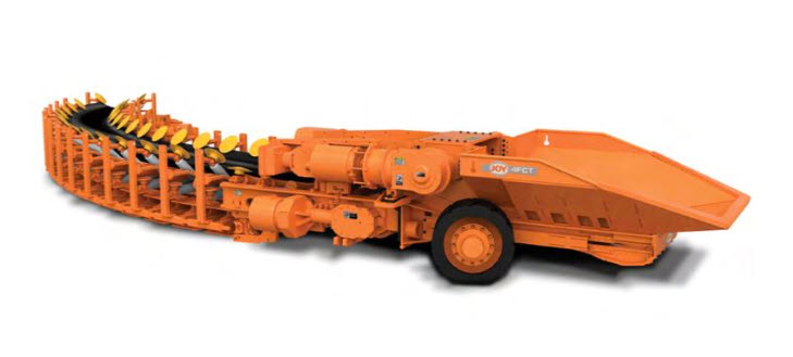
The area around the active working faces is very dynamic. It is difficult to construct semi-permanent infrastructure in this area; and it is for this reason that intermediate haulage has evolved. If we are to make an improvement, we would need a conveyor belt that was mobile, i.e., it could travel around the working faces, following the continuous miners or loaders. Prototypes of such systems have been built for use in underground metal mines to replace LHDs, but they have met with little success. In the case of soft rock applications, and notably coal and salt, there are commercially available technologies to meet the need, in specific circumstances. Here is a picture of a commercially available flexible conveyor. These units can turn corners and can be piggybacked to provide a continuous path of several hundred feet between the continuous miner and the section dump point. Recall that it is at the section dump point where the coal is fed onto the main or outby conveyor belt. This technology is being used successfully in some salt mines, but has found limited application in underground coal mines. For reasons that lie beyond the scope of this discussion, they work best in shallow mines with small pillars; and that is a small subset of all underground coal mines.
But not to despair, there is one other option in limited but successful use.
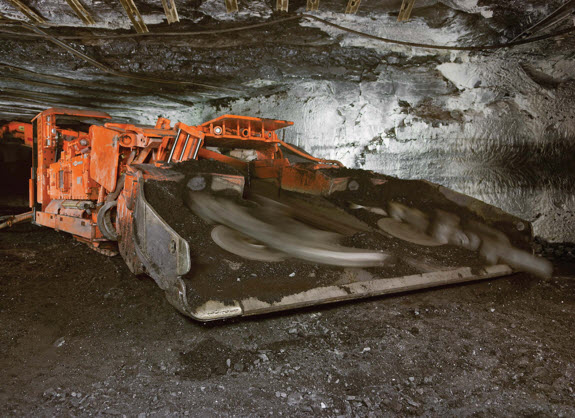
Rather than having the continuous miner load into a shuttle car, and being captive to the availability of shuttle cars, what if we allowed the continuous miner to dump onto the mine floor? Sounds crazy, right? But, not really. We could use a loading machine to clear away the pile, and trust me, loading machines can load a shuttle car very quickly. So, the shuttle cars would queue up for loading, but if there were a delay, the continuous miner would be able to continue mining without incurring a delay. Sure, the pile behind the machine might grow rather large, but no worries. The loading machine will get rid of it quickly. As you can see in the picture, the loading machine has a larger set of gathering arms than the continuous miner. The operating principle is the same, however: the gathering arms pull the coal into the belly of the machine and onto the chain conveyor.
And now, having addressed the quest for continuous, we not only understand the technology options, but we’ve become more familiar with the key concepts of availability, system delays, and batch versus continuous haulage.
There is one final unit operation to study, and one that is a huge part of most mining methods. It’s generally one of the more popular topics among mining students as well: explosives and blasting!