5.1.2: Materials Handling
5.1.2: Materials Handling
Materials handling is concerned with how we move (haul) the mined material out of the mine to the processing plant. Before looking at specific haulage options, we should talk about a few overarching concepts. The first is intermediate haulage.
At the working face, i.e., where the ore is being freed from the deposit, we are going to load the ore into some type of haulage. If we are in a surface mine, it is likely that we’ll load the ore into a truck, which will haul the ore the entire way to the plant, dump it, and then return to the face for another load. If we are in an underground mine, it is likely that the material at the face will be loaded into a haulage vehicle and then transported to an intermediate dumping point. From the intermediate point, a different haulage device will be employed. Sometimes, there could be even another subsequent intermediate device. As an example, assume we have a mine in which LHDs are used to load out the ore at the draw point (face) and transport it to a dump. The dump point is at an ore chute in the rock that funnels the ore to a lower level where it is loaded into rail cars, along with the ore from many other dump points. A train may pull these cars several miles out of the mine and to a processing plant. Or, the train may take the ore to a transfer point at the bottom of the shaft, where the ore will be dumped and transported in large ore skips (buckets) up the shaft to the surface. The choice of a specific type of materials handling is based on optimizing the overall process. Smaller and maneuverable equipment is best suited at the face, whereas larger capacity, but more permanent equipment may be indicated to move the material out of the mine. As we look at different mining methods, this will become even clearer.
Let’s identify the common choices for materials handling, to move material from the face to the plant.
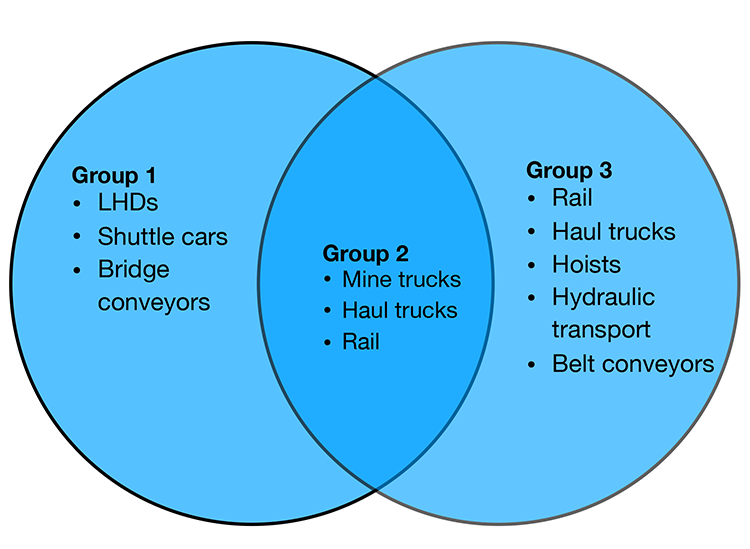
Click here to see a text description.
- Group 1
- LHDs
- shuttle cars
- bridge conveyors
- Group 2
- mine trucks
- haul trucks
- rail
- Group 3
- rail
- haul trucks
- hoists
- hydraulic transport
- belt conveyors
I’ve arranged them into three groups. The equipment in the first group is typically used for short haulage runs from the face to an intermediate dump or transfer point. The equipment in the third group is used to move the material out of the mine and to the plant. The equipment in the second group can fall into Groups I or III. In some instances, the equipment shown in Group II will be used to move the material directly from the face to the plant, whereas in others, it will be used to transfer the ore to an intermediate point. Again, the choice and rationale will become clearer as we learn about the requirements inherent to the different mining methods. Let’s look at the general characteristics of these materials-handling modes. We’ve already discussed LHDs, so let’s begin with shuttle cars.
5.1.2a: Shuttle Cars and Bridge Conveyors
5.1.2a: Shuttle Cars and Bridge Conveyors
Shuttle Cars
Shuttle cars are a low-profile intermediate haulage option used predominantly in underground coal and some industrial minerals mines. Ore is loaded into the shuttle car at the face, and then it trams a relatively short distance, dumps its load, and returns to repeat the cycle. Shuttle cars are manufactured in different sizes to work in very thin seams of less than 36” to high seams, greater than 72”. The capacity is dependent on the size, but a typical capacity is 6 – 10 tons. The shuttle car normally dumps into a feeder-breaker, which crushes any large lumps and feeds the load onto a conveyor belt. Variations of the shuttle car include ram cars and haulers.
Bridge Conveyors
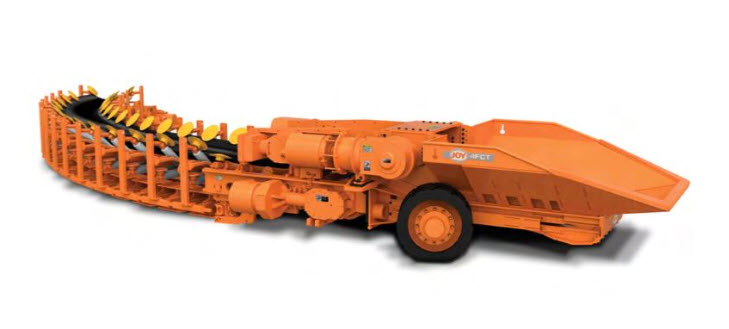
Bridge conveyors are belt conveyors that are designed to move material directly form the face to a final point, e.g., a spoil pile in surface mining, or a transfer to a main conveyor in underground mining. Unlike main-belt conveyors, which are semi-permanent, bridge conveyors are designed to be easily maneuverable, to keep up with the active mining face. Looking at this bridge conveyor, known as a flexible conveyor train, you can see the hopper where ore is loaded. There is a feeder in this hopper that meters the ore onto the rubber conveyor belt. Note that the belt can go around corners. These have found limited application in underground coal and salt mines.
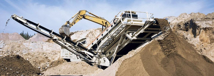
Here is an example of a conveyor being used to transport spoil (overburden) directly from the bucket of an excavator to spoil piles.
5.1.2b: Mine Trucks, Haul Trucks, and Rail (Trains)
5.1.2b: Mine Trucks, Haul Trucks, and Rail (Trains)
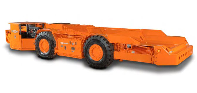
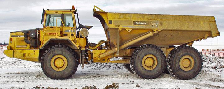
The distinction between haul trucks and mine trucks is subtle but important. Mine trucks are generally designed for underground use in more confined spaces. They will have an articulating joint to allow turning in a tighter radius. The capacity will also be less because of clearance restrictions. Nonetheless, capacities of 15 to 60 tons are common. These mine trucks, as pictured here, are commonly used in underground metal and nonmetal mining, and they are as likely to transport the ore directly from the face to the plant as to transport to an intermediate transfer point.
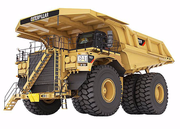
Haul Trucks
Haul trucks are designed to transport larger loads than mine trucks, and in some underground mines where there is sufficient room, you will find haul trucks. For example, in a salt mine where a 90’ thick seam is being removed, you can fit a large truck of 60–100-ton capacity, although, in underground metal/nonmetal mines, a size of fewer than 60 tons would be more common.
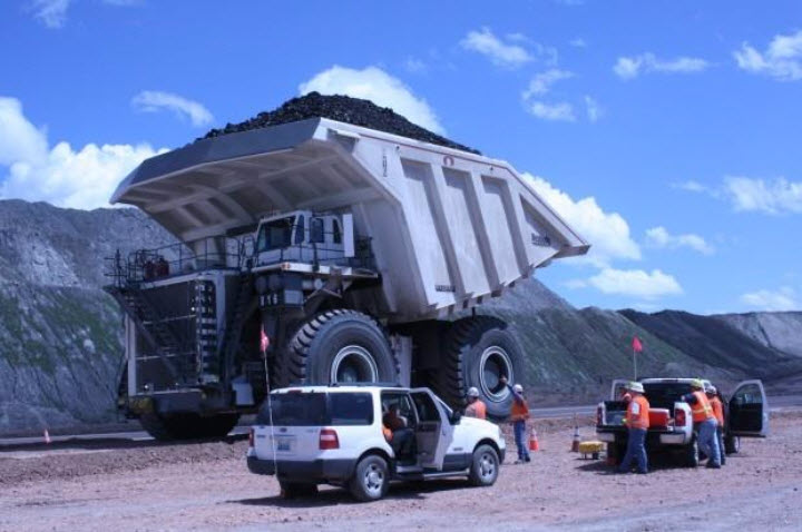
This haul truck holds nearly 450 tons and is in use at a surface coal mine in the Powder River Basin.
Rail (Trains)
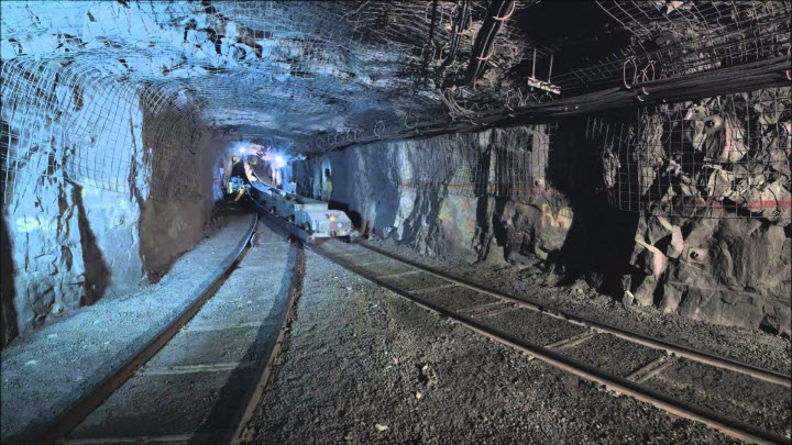
Rail haulage was once very common in underground mines, and even in some surface mines. It has the advantage of being able to transport large loads at a low cost. It has fallen out of favor because it has inherent problems that make it unsuitable for many of today’s high production mining systems. Nonetheless, it is still used. In modern coal mines, for example, rail haulage will often be used to transport equipment and supplies, whereas conveyors will be used to transport the coal. The reasons for this will become evident when we look at batch and continuous operations in the next lesson. Rail can be used as an intermediate form of haulage, or as the means to transport the ore out of the mine to the plant. The locomotives and cars used may be of lower profile, like the one shown here.
5.1.2c: Hoists, Hydraulic Transport, and Belt Conveyors
5.1.2c: Hoists, Hydraulic Transport, and Belt Conveyors
Deep underground mines may be accessible only through a shaft that is sunk from the surface to the working levels of the mine. Not only will all workers and supplies access the mine through the shaft, but also all ore will have to come out of the shaft. This is accomplished by hoisting systems. Three major components of a hoist are the skip, which holds the ore and is attached to the winder on the surface by wire ropes, the headframe and the hoist winder (winch and drum). The headframe supports the sheave wheel over which the wire rope is connected to the skip. As the drums in the surface hoist house wind the rope onto the drum, the skip is pulled to the surface, where it is dumped.
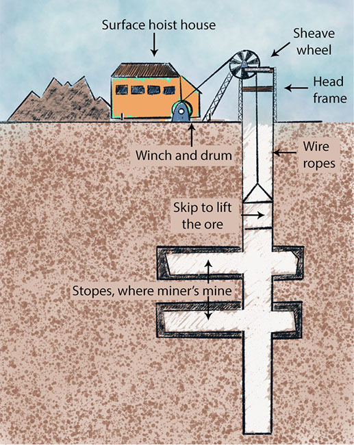
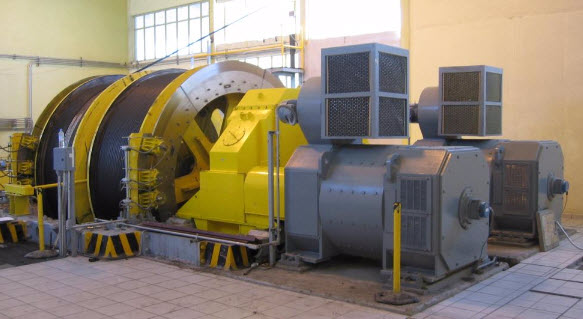
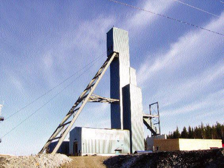
The winder is shown in the first picture below, the bottom headframe in the second, and the bottom dump skip in the third. Often a different type of hoist from the one shown is used, which allows a skip to be connected at the bottom and the top of the shaft so that as the one is being unloaded, the other is being loaded. A skip typically holds up to 50 yd3 of material.
Hydraulic Transport
Hydraulic transport, often known as a slurry transport system, is used in limited circumstances. The ore is mixed with a fluid, e.g., water, and pumped from the mine to the processing plant. It is an energy-intensive system and is best suited to a limited class of ores such as phosphate, which is already mixed with water in the mining process, or other ores obtained from hydraulicking or dredging. The system is straightforward, consisting of high horsepower slurry pumps every few miles and a large diameter pipe, greater than 2’ in diameter.
Belt Conveyors
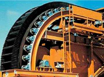
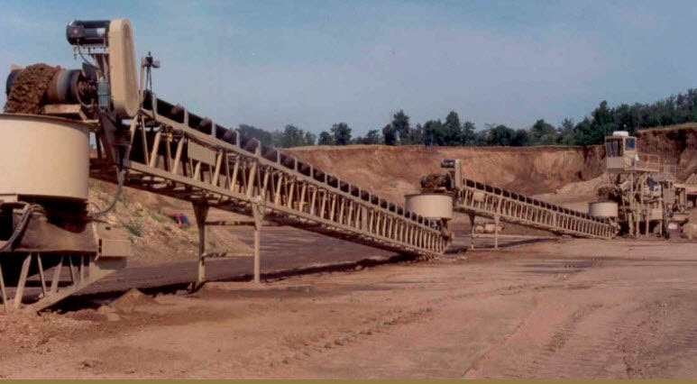
Belt conveyors are the workhorses of modern mines, both surface and underground. The belt conveyor consists of the belt, which is constructed of multiple plys to provide the required strength and wear resistance; the belt is constructed into a closed loop and stretched between a head and tail pulley; the belt is supported with idlers between the head and tail, and they maintain the appropriate trough shape as well as support the weight of the material in the belt. The head pulley is connected to a motor to power the conveyor. These belts range in width from a few feet to more than 8’, and can transport thousands of tons of ore per hour. Although each belt is of limited length based on mechanical constraints, they can be combined into long runs by constructing transfer points to allow one belt to dump onto another. In this fashion, complex networks can be assembled. Here is an example from a surface mine.
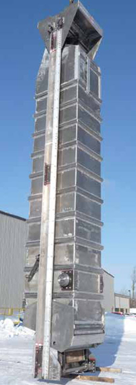
Many years ago, the incline angle of the conveyor was limited by the angle of repose of the ore being conveyed. If this angle was exceeded, the material would begin to slide down the conveyor and would no longer be conveyed upward. Modern designs and significant material improvements now permit belt angles up to 90°, as shown in the second picture.