Module 8: Underground Mine Development
Module 8 Overview
Module 8 Overview
Fewer than 10% of the mines in the United States are underground mines. Given a choice, we’d always choose to mine by a surface mining method, as surface mining is less expensive than underground. Unfortunately, we don’t usually have a choice! Certain commodities are found predominantly deep beneath the Earth’s surface – too deep to consider surface mining; and notable examples include gold, lead, molybdenum, platinum, potash, trona, salt, silver, and zinc. Other commodities are commonly mined on the surface, but because of their value, they are deep mined as well; and notable examples include diamonds, metallurgical & thermal coal and copper. In recent years, a third reason for going underground has emerged: the commodity is located in a suburban or urban environment, and local zoning ordinances preclude a surface mining operation. We are seeing this primarily with limestone. Finally, as time passes, the reserves that are easiest to exploit have been mined. Increasingly, we are having to mine deeper and deeper, and under more adverse conditions. The following article from the Wall Street Journal illustrates this well: "Mining a Mile Down: 175 Degrees, 600 Gallons of Water a Minute. [1]" Can you imagine mining under such conditions? It is a great engineering challenge, and we will see more and more of this!
The development of an underground mine follows a similar process to initial stages of surface mine development. A site has to be prepared, office buildings, shops, warehouses, and mineral processing facilities need to be constructed. And as with surface mine development, the timing of the infrastructure will minimize any premature upfront cash expenditures. The significant difference between surface and underground development is access to the orebody. This is usually easy to accomplish in surface mining because the orebody is close to the surface and often it is only necessary to remove vegetation, the soil layers, and a modest amount of overburden. By contrast, accessing a deep orebody can take considerable time, effort, and money. In many cases, we can access and begin mining a surface deposit within weeks, whereas it might take several months of even a year or more to access a deep deposit.
Learning Outcomes
At the successful completion of this module, you should be able to:
- demonstrate knowledge of the four types of openings used to access an ore body for underground mining, and specifically:
- when each would be selected, i.e., the pros and cons,
- where they would be located, and
- the materials handling options for each type of opening after the mine is in production;
- demonstrate knowledge of the process / unit operations for developing shafts, slopes, drifts, and box cuts, including the type of equipment used;
- define, and/or draw & label as appropriate, the basic terms used to describe underground mining methods and activities - specifically, the common deposit and spatial, directional, and excavation terms (see text pp 79-83 for listing and definitions);
- sketch a generalized underground metal mine, for the purpose of illustrating the basic infrastructure of such a mine;
- name the three classes of underground mining methods, and describe the distinguishing characteristic of each class;
- demonstrate an understanding of the conditions under which one method would be selected over another. Describe the “defining” or “distinguishing” characteristics of each method;
- describe and sketch the essential elements of three major unsupported methods: room and pillar, a.k.a. stope and pillar, shrinkage stoping, and sublevel stoping. Name some commodities mined by these methods;
- draw a typical room and pillar coal mine layout showing mains, submains, and panel entries;
- describe the sequence of development and production for each method; identify typical equipment utilized for the associated unit operations; additionally:
- for the room and pillar method, describe conventional, continuous, and longwall mining,
- for shrinkage stoping, describe the more popular variant known as VCR,
- for sublevel stoping, describe the variant known as bighole stoping;
- describe and sketch the essential elements of the major supported method known as cut and fill. Explain what is meant by drift and fill, undercut and fill, and overhand cut and fill;
- describe the sequence of development and production for the cut and fill method; identify typical equipment utilized for the unit operations and auxiliary operations;
- explain the concept of the historical methods of square-set stoping and stull stoping, and in what very limited circumstances they might be applied today. Describe how cut and fill mining can be used in conjunction with another primary mining method to increase the extraction ratio;
- describe and sketch the essential elements of the major caving methods known as sublevel caving and block caving, as well as another important caving method known as longwall mining (for coal and noncoal).
Lesson 8.1: Orebody Access
Lesson 8.1: Orebody Access
There are three common methods to access an orebody under deep cover. They are shafts, declines, and adits/drifts.
Shafts
A shaft is a vertical or nearly vertical opening driven from the surface to the deposit. The cross-section of a shaft is usually elliptical or circular, as these shapes are stronger than square or rectangular openings, provide less resistance to airflow, and maximize the useful space per dollar spent on the shaft. The diameter or dimensions of the opening are based on the purpose for which the shaft will be used, and the diameter can commonly range from around 6’ to 30’, and sizes outside of this range occur occasionally. The shaft may be used solely to hoist ore to the surface, provide ventilation, or to transport people and supplies. Commonly, shafts are partitioned and serve more than one purpose.
Declines
A decline can take the form of a slope, which is a straight opening driven at an angle, or a ramp, which is similar to a slope except that it is generally helical in shape. The angle of the slope, as well as the design radius and the angle of the ramp, depend on their intended use. The dimensions of a decline will depend on the purpose for which it is to be used. A slope may be outfitted with a belt conveyor to move ore out of the mine, or perhaps there will be track for rail haulage. The slope may be partitioned with a top and bottom compartment to facilitate multiple uses, including ventilation. A ramp, on the other hand, is used primarily for access, to move people, supplies, and ore between levels or to the surface, and it will be sized to accommodate the largest piece of equipment in use. The ramp may also be used for ventilation and utilities, e.g., electric power cables and water lines.
Adits/Drifts
Openings that are driven within the ore and follow the seam or vein are known as adits when they are driven in metalliferous veins or drifts when driven in coal and nonmetal seams. Functionally, there is little difference between a slope and a drift or adit. It’s simply that one, the slope, is driven in the country rock, i.e., the nonmineral-bearing rock around the ore, whereas the other, the adit or drift, is driven in the ore. In the past, it was common to find veins or seams that intersected the surface. The practice, as you would expect, was to begin mining the ore where it intersected the surface, and then to follow the vein or seam and continue mining. In some cases, this led under a mountain, in other cases, with a vein or seam that was dipping at some angle, the driven opening could go quite deep. Regardless, the opening at the surface, or the entry point into the mine, is known as an adit or drift. Thus, when you hear the term slope, you will know how that differs from drift or adit. To be honest with you, I find some of these definitions and the subtle differences among them to be a bit tedious. But, they are in common use, and you should know what they mean, and you should use the correct term.
And number 4: the Box Cut
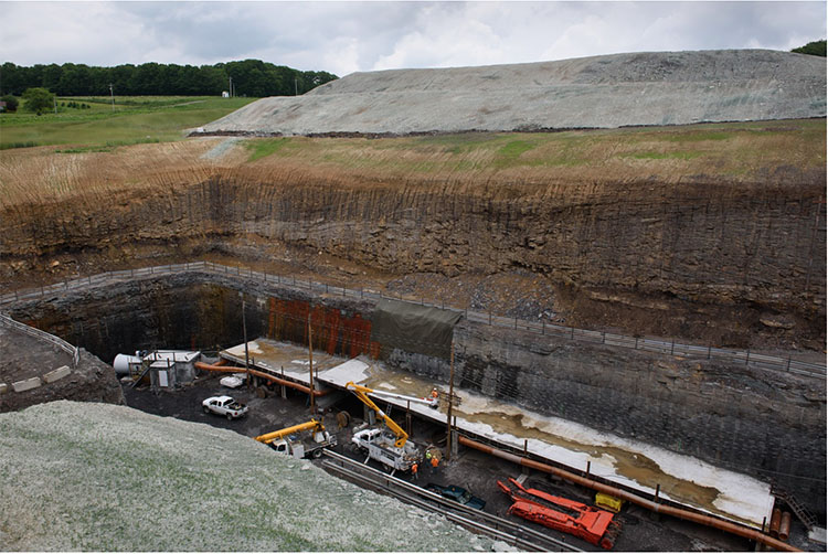
There is a fourth means of access that is used infrequently, but is common enough to warrant its own category. It is known as a box cut. You may recall learning this term earlier, as this term is taken from surface mining, and specifically the open cast mining method known as area mining. In that method, an initial cut is made to start the process, and the material from this cut is hauled away. Typically, this cut looks like a box: it is few hundred feet wide and several hundred feet in length, and may be up to a few hundred feet in depth. However, the dimensions are specific to the application. You’ll find this method of access being used in coal and limestone, and often the depth of the box is less than 100’. The idea is to have the floor of the box at the same level as the seam. This allows openings to be driven into the seam. And what would these openings be called? Yes, drifts. Of course, roadways need to be constructed to allow equipment, supplies, and personnel to be transported down into the box cut, and into the mine. Sometimes, the box will be enlarged to allow placement of buildings, crushers, and so on within the box cut.
Here is a photo of a box cut to access a coal seam. You can see the overburden that was removed and carefully place in the background. Note the overburden layers and the rock overlying the coal seam. In the front left side of the picture is an access road into the box, although it is difficult to see clearly.
The choice of an access method is generally limited. The following list illustrates the factors that go into the selection.
- If the seam or vein intersects the surface, a drift or adit will be the choice.
- If the seam is close to the surface, i.e., typically within a few hundred feet, a box cut will receive serious consideration.
- The construction cost of a shaft is about three times the cost of a slope; however, the construction footage of a slope is generally at least three times that of a shaft.
- The deeper the orebody, the more likely that a shaft will be used.
- Transporting large equipment into a mine is more easily accomplished with a slope rather than a shaft. Large equipment must be cut into pieces and reassembled underground if there is no slope access.
- Construction of a slope is more challenging in difficult ground conditions, and could sway the decision to choose a shaft.
- A shaft limits the materials handling to batch operations, which is a serious limitation, as discussed earlier in the semester.
- Quite a bit of real estate is required to put in a slope, and a ramp can be constructed under a much smaller surface footprint.
- A ramp precludes continuous haulage, which can be a disadvantage.
- Coal mines require two means of access, and it is common for deep mines to use both a slope and a shaft. This allows them to realize the benefits of both means of access.
This is not an exhaustive list of considerations, but it is representative. As you progress in your studies and learn more about ground control, ventilation, and materials handling, the decision criteria will become even clearer to you. These openings must serve as primary conduits for ventilating air – either fresh air intakes or exhaust air returns, and that will impact the size and configuration of the choice. The material handling options, which center around batch versus continuous, will be important factors in the decision, as well as the need to move very large equipment on a regular basis. You’ll recall from our discussion of auxiliary operations that we have several materials handling options. These can be summarized here by access type.
| Shaft | Slope/Drift/Adit | Ramp | Box Cut |
|---|---|---|---|
| Hoist | Rail | Rubber-tired haulage | Rail |
| Vertical belt | Belt | Belt | |
| Elevator | Inclined hoist | Rubber-tired haulage | |
| Rubber-tired haulage |
Placement of the Access Opening
What about the placement of the access opening on the property? All things being equal, you’d probably want the access to be near the centroid of the orebody. The location of roads and rail service to your property could affect the decision, as could topography. You wouldn’t want your shaft to be located at the lowest natural drainage point of your property, and permitting constraints limit the placement as well. In general, you cannot place an access opening down dip from the seam that you are mining because any water accumulation in the mine would then drain out of the mine. That can be an environmental issue that you have to address. Ground conditions may affect your placement decision as well. Unless there are overriding circumstances, logistical considerations will weigh heavily in your decision of where to locate the shaft, slope, ramp, or box cut.
8.1.1: Construction of the Access
8.1.1: Construction of the Access
We should talk a little bit about the construction of these means of access. The construction of the drifts, adits, slopes, and ramps does not differ significantly from the unit and auxiliary operations for mining the ore, which we discussed previously. However, these access openings are generally, except to remain serviceable for the life of the mine, unlike many of the other workings that are in use only while the ore in that part of the mine is being exploited. Consequently, extraordinary measures can be justified to ensure the stability of these openings over many years. What are these measures? Reinforced concrete liners, steel arches, and/or additional rock and cable bolts to ensure long-term stability. Some rock types deteriorate when exposed to moisture, and you may shotcrete these surfaces to prevent oxidation and deterioration.
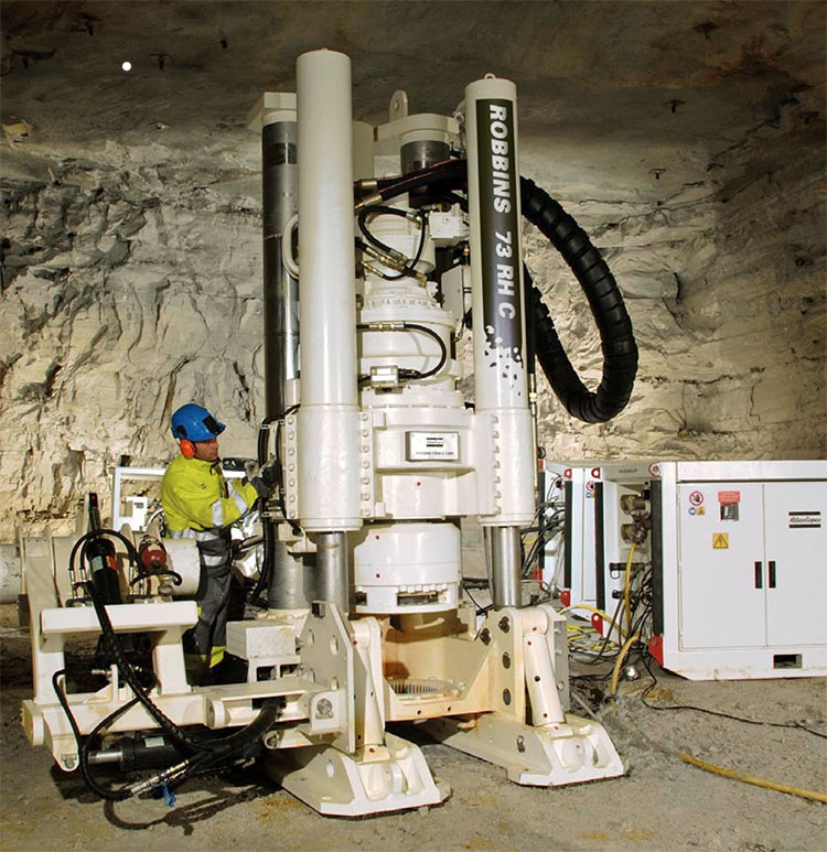
Shaft sinking, on the other hand, may involve some operations and equipment that we didn’t address directly in our study of unit and auxiliary operation. Shaft sinking can be accomplished with a conventional cycle, i.e., drill-blast-muck-hoist, or a continuous cycle using a blind-shaft boring machine. Let’s talk about each cycle.
Previously, we talked about the conventional cycle used in mining as consisting of the unit operations: drill-blast-load-haul. The same unit operations are used to sink a shaft, but the name for loading has changed to mucking and the name for hauling has changed to hoisting. As we sink a shaft into the earth, we cannot load the blasted material with a wheeled loader for example and haul the blasted material off to a dump… obviously! Instead, we use a clamshell mucker to grasp the broken rock and drop it into a large hoist bucket. When the bucket is full, it is hoisted to the top of the shaft and dumped into a waiting truck, where it will be hauled to a dump pile. Hence, the name change for loading to mucking and hauling to hoisting in the conventional cycle for sinking a shaft. It should be noted that the word muck refers to any broken, i.e., blasted, rock, and the word mucking is an old mining term for the operation of loading out muck. Here is a video illustrating the mucking and loading operations in a shaft. This example is for a fairly shallow and small shaft. Larger and deeper shafts involve more complex arrangements, consisting of multiple deck stages and equipment. Nonetheless, this video (2:28) illustrates the basic concept.
During the sinking of the shaft, the auxiliary operation of ground control is generally crucial. The first tens or even a hundred or more feet are driven in relatively poor quality material, e.g., soils and weathered materials that will not stand on their own. In other words, they would tend to fall into the shaft. In areas of past glaciation, the overburden may consist of a hundred feet or more of loosely consolidated rubble. In these areas, the only way to sink a shaft is to freeze the overburden, drill and blast through the frozen material, and then immediately place a liner in the shaft to support the shaft walls. Glaciers made it as far south as Illinois, for example, and so, if you want to sink a shaft down to a coal deposit in the Illinois basin, chances are good that you will have to freeze the alluvial till, i.e., the unconsolidated overburden. Freezing is accomplished by drilling and placing refrigerant pipes around the location of the future shaft, setting up a large refrigeration system, and pumping coolant through the pipes until the ground is frozen. Then, the shaft sinking can begin. Here is a good video (4:37) to illustrate a shaft sinking process in which freezing the overburden is part of the project.
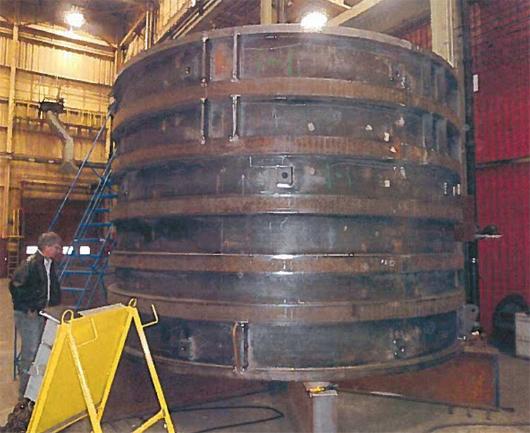
The ground support to maintain the integrity of the shaft walls may consist of rock bolts and wire mesh, but will normally require the use of liners. The liners could be timber, which was used in the past, mortared brick liners, which are also a thing of the past, or most common, concrete liners. In most cases, the concrete liners, a foot or more in thickness, are poured in place. Sometimes, precast liner segments are delivered to the site and set into place, and then a grout is pumped behind the liner to fill the space between the rock wall and the liner. The liners will change over the depth of the shaft depending on the need. If there is a problem with ground water infiltration, steps will be taken to seal the shaft in the water-bearing horizons. This is not as simple as it may seem. At depth, the hydrostatic pressure on that water could reach 500 to 1000 psi or more! To withstand these forces, specially constructed steel liners are used. They may be made out of steel that is ½ to 1” thick, and then welded into place with a concrete ground pumped behind the liner to fill the void between it and the shaft wall. Here’s a picture of such a liner in the shop prior to delivery.
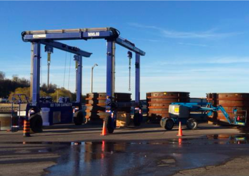
And here is a picture on site. You can see the liners waiting to be installed, along with the gantry for lowering them into the shaft. In this case, they are being set in the first 900’ of the shaft.
8.1.2: Revisiting "The Quest for Continuous"
8.1.2: Revisiting "The Quest for Continuous"
In a previous lesson on “the quest for continuous,” we looked at the motivation for replacing conventional cycles and the equipment for doing so. In the case of shaft sinking, the same principles have been applied. A variety of boring machines has been developed, and consist of a rotating and bit-laced head, a built-in materials handling system to clear the cut material and send it on its way to the surface, and the means for advancing, guiding, and controlling the borer. Likely, there are stages immediately above the borer that are outfitted to allow placement of liners. The following video clip (10:35) provides a detailed look into the functionality of a modern shaft boring machine.
In soft to medium harness rock, the boring machine is the preferred choice, as it can be done faster and at a lower cost than with conventional methods. However, in hard materials, a conventional drill and blast cycle is the only viable choice. This is similar to what we find for continuous mining methods in various deposits. There is one other machine of note for smaller diameter shafts – the raising boring machine.
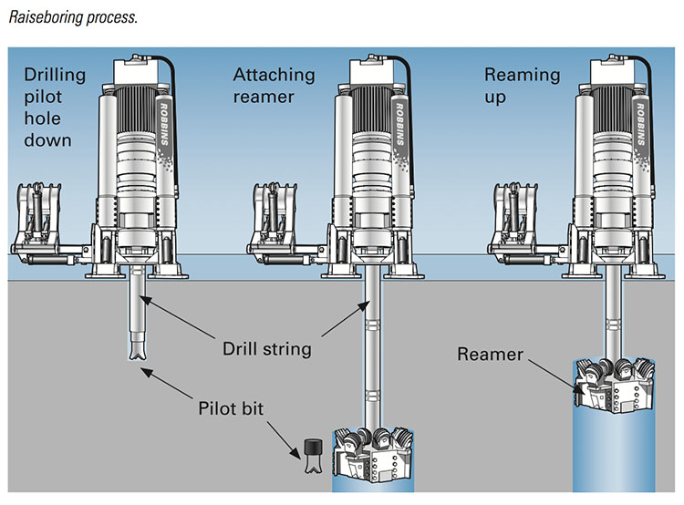
Small diameter shafts, say less than 10’ in diameter, are required in many applications. They are used for emergency escape hoists, ventilation shafts, and travel ways between levels in a mine. The latter are known as raises, and this is where the name, raise borer, originated. In the good old days, raises and small diameter shafts were driven using conventional cycles. Today, a continuous cycle is used in most cases.
Raise boring requires that the bottom of the raise terminates in an existing mined opening. The first step in using a raise borer is to drill a pilot hole down to the exiting opening. Once completed, a large diameter cutting head is threaded onto a drill steel that connects to a power source on the surface or the upper level. The power source, i.e., the raise borer, provides thrust and rotation for the cutting bits. The cuttings fall to the lower level where they must be loaded and hauled. Take a look at this figure – it makes more sense if you can see it!
Here is a picture of the power unit. Raise borers can excavate an inclined open as well as vertical, and they can bore upward, although that is done with less frequency.
8.1.3: Odds and Ends
8.1.3: Odds and Ends
There are a few odds and ends – points that need to be made, but which I haven’t discussed until now. I’ll finish out this lesson by covered these.
The shaft collar is the name given to the point where the shaft intersects the surface, and it is also a structural component of the shaft. It is typically reinforced concrete and it will be either anchored into bedrock or tied into a liner that is anchored in the bedrock. The collar serves an important structural function for equipment associated with the shaft, and it is used to limit surface drainage into the shaft.
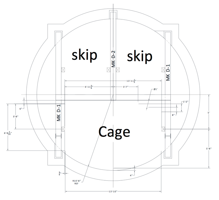
A building or structure is associated with the shaft. If there is a hoist, there will be a headframe. Hoists are always used to haul ore up the shaft and out of the mine. The hoist may also include a cage. This is a steel structure, typically with open steel mesh construction giving it the name “cage” used to transport miners and supplies. The trip to the bottom or back up to the top is known as a mantrip. In deep mines, the cage will likely have multiple floors so that a hundred or more miners can be transported at one time. When it takes 15 to 30 minutes to make the descent, you want to minimize the number of trips! Hoists are of two general types: drum or Koepe (friction hoist). You will learn how to design both in MNG 404, and we won’t go into the differences here, although they are discussed in the text. If there is no need for a hoist, i.e., to transport ore, but only a need to transport people and supplies, then an elevator would normally be used. The elevator is similar in construction to one that you would find in a high-rise office building of 100 stories.
Here is a cross-section of a shaft showing the compartmentalization or multi-function layout. Half the shaft is dedicated to hoisting ore, and there is a skip at the bottom and a skip at the top of the shaft. As one skip is being unloaded at the top, the other is being loaded at the bottom. For reasons that will become clearer later on, this is a Koepe hoist. The other half of the shaft is dedicated to a cage. This cage is connected to a drum hoist. You might want to think about why the Koepe hoist is used in the one case and the drum hoist in the other.
Shaft development practices have changed over the last few decades, with bored shafts being much more common and the "circular" shaft becoming all but universal for large shafts in new mines. In coal mining, about half of all shafts are now sunk by blind-boring methods. It has become common for main shafts up to 16’ to be drilled in this fashion. In addition, many coal mining companies now use bleeder shafts to simplify their longwall ventilation systems. These are sometimes drilled using blind-boring rigs. Raise-bored shafts are done as well, but access must be available underground to make this feasible, and the need for a mucking and transportation system underground makes this alternative less favorable. For large shafts, greater than 20’, in coal mines and for most metal and nonmetal mine shafts, conventional shaft-sinking methods are still commonly used.
We’ve talked little about slopes and ramps because their construction differs little from the conventional mining cycle. However, it should be noted that tunnel-boring machines are being used with increasing frequency to drive large slopes of considerable length. The cost of bringing a tunnel boring machine to a site, and setting it up is very high, and can only be justified for large diameter slopes that are greater than a few thousand feet.
The slopes used in today's coal mines are normally driven with two compartments: an upper compartment to accommodate a belt conveyor and a lower compartment containing track that is normally used for personnel and supply transport. The two compartments are separated by a horizontal concrete divider and are supported by bolts, wire mesh, or steel arches. Slopes in coal mines are often horseshoe-shaped, with widths of 17 to 20’ and heights of 13 to 14‘.
The next lesson will address the "building blocks" or basic elements of underground mines. Once we have gained access to the deposit, we are ready to begin development of the underground workings. We'll be introduced to the elements of those workings in the next lesson, and after that, we will be prepared to examine the development of underground mines for the different mining methods.
Before moving on, use these interactive activities to test your knowledge of important terms in this lesson.
Lesson 8.2: Elements of Underground Mines
Lesson 8.2: Elements of Underground Mines
Underground mines share common elements regardless of the specific mining method. Examples include pillars, stopes, and drifts. It is necessary to understand these words and to use them correctly. Perhaps the most onerous task in this course is to memorize these definitions. There’s simply no way around it. You have to memorize them and understand conceptually what they mean. You’ve done already for a variety of terms including burden, spacing, highwall, and box cut, among many, many others. The difference here is that you are being hit with a relatively large number of terms all at once. Of course, if you heeded my advice earlier in the semester, then you have been memorizing a few of these each week, and now you are in good shape! I won’t ask if you’ve done that…
Let’s dive into the definitions!
The text divides the definitions into three broad categories.
Deposit and Spatial
These terms are useful to describe the deposit and major features that define the mine within the deposit.
Directional
These terms allow us to communicate the relative location of something within the mine, or the direction in which an activity is moving.
Excavation
These terms capture the features that we create within the deposit through our mining activity.
I am not going to ask you to tell which terms fall into which category. I’m only trying to explain the underlying rationale for the groupings. Some terms are rarely used or are specific to just a few uncommon mining methods. I’ll try to distinguish those from the ones that are used widely. Obviously, you will want to know the latter quite well! I recommend that you read through the terms, and then refer to the three figures that follow to help understand the meaning of the terms, and then go back to the definitions with the goal of memorizing them. Ok, with this out of the way, let’s get to it!
8.2.1: Deposit and Spatial Terms
8.2.1: Deposit and Spatial Terms
If we are in a horizontal deposit and we mine an opening into the deposit, that opening will have a top and a bottom. We often use those terms. We might say, “this mine has good top,” and we mean that the rock structure at the top of the opening is competent. Or, we might say, “that seam is underlain by clay, and the bottom is terrible,” and we mean that it is difficult for equipment to move around because of the poor condition of the bottom. In a tabular deposit, we frequently refer to the top as the roof, and the bottom as the floor. Conceptually this aligns with our everyday experiences – if someone refers to the roof or the floor, we know what they mean. Likewise, if we refer to the top or bottom of our mined opening, we intuitively know what is meant. As I indicated, these four terms, top, bottom, roof, and floor, work well for tabular deposits, and are used in coal, trona, potash, salt, and stone mines, for example.
When we move into metal mines, we will not hear those terms. There are a few reasons for this. The mining methods and culture evolved differently in metal versus coal and some of the nonmetals, and they each evolved their own terminology. It’s similar to the situation with the word we use to describe a soft drink. In some parts of the country we would ask for a bottle of “pop.” In another region, we would request a bottle of “soda.” If you go into an area and use the “wrong” term, people may snicker and smile, but they will know what you mean. The same is true for some of these mining terms, except that in addition to smiling, they will likely think that you are a rookie and perhaps are not really a mining person. If, in fact, you are a mining engineer, then that would not be a good thing!
The second reason for the difference in terms relates to the spatial complexity of many metal mines and metalliferous the deposit. In a steeply dipping deposit, for example, the concept of a roof and floor is less useful than hanging wall, footwall, and back. And, of course, there can be crossover in terms. A mining engineer working in a tabular limestone deposit will refer to the top of the opening as the roof, unless they have a background in the metal industry, and then they will refer to it as the back. Don’t despair! As you look at the figures, study the definitions, and read more about the methods, it will become perfectly clear. On with the definitions!
- Top: Overlying surface of an underground excavation.
- Bottom: Floor or underlying surface of an underground excavation.
- Roof: Top or overlying surface of an underground excavation.
- Floor: Bottom or underlying surface of an underground excavation.
- Back: Roof, top, or overlying surface of an underground excavation.
- Country rock: Waste rock adjacent to a mineral deposit; and sometimes called host rock.
- Wall rock: Country rock boundary adjacent to a deposit.
- Footwall: Wall rock under the deposit.
- Hanging wall: Wall rock above a deposit.
Initially, students are uncertain about which is the footwall and hanging wall. If you have doubts, remember this: these two terms only have meaning if the deposit is dipping at an angle; and pretend the opening in the deposit is a sliding board, and that you are going to slide down – and when you do, your butt will ride on the footwall. Now you’ve got a silly but effective way to keep it straight. Speaking of the footwall, you will notice that the shaft and the workings are located in the country rock and on the footwall side of the deposit, not the hanging wall. There’s a good reason for that. Why do you think that is the case?
All right, onward with the definitions! Here are two more of major importance.
- Dip: Angle of inclination of a deposit, measured from the horizontal; also pitch or attitude.
- Strike: Horizontal bearing of a tabular deposit at its surface intersection.
We’ve talked on various occasions about deposits that dip, and so you already have a familiarity with the term. A synonym that is sometimes used is pitching. The terms steeply pitching or a steeply dipping are synonymous. This is true whether it is a seam, vein, deposit, or orebody.
If you’re a surveyor or a geologist, then you are very familiar with the concept of strike. The dip of a deposit can have a profound impact on the type of mine that we develop, but not so for the strike! The strike provides us a direction on the compass to orient our workings, but little more than that for the mining engineer. Now, for structural and economic geologists… they can get excited by the strike of the vein!
In the process of excavating an opening, i.e., mining, we will often leave behind sections of the orebody, for the sole purpose of providing structural support to the overlying layers of rock. These unmined blocks are called pillars, and they are necessary to prevent a collapse of the mined openings. Certain pillars are given specific names, as follows.
- Pillar: Unmined portion of the deposit, providing support to the roof or hanging wall.
- Crown pillar: Portion of the deposit overlying an excavation and left in place as a pillar.
- Sill pillar: Portion of the deposit underlying an excavation and left in place as a pillar.
- Barrier pillar: a pillar designed to withstand major loads.
- Yield pillar: a pillar designed to yield, but not fail under heavy loads.
Crown and sill pillars are commonly found in mines for steeply pitching deposits, and barrier and yield pillars are commonly found in tabular deposits that are nearly horizontal.
Finally within this first group, three more terms:
- Capping: Waste rock overlying the mineral deposit.
- Rib: Side wall of an excavation.
- Gob: Broken, caved, and mined-out portion of the deposit. Often, mined out areas will begin to cave, and this is a normal part of the process. The caved area is known as the gob, or in some parts of the world, the goaf.
8.2.2: Directional Terms
8.2.2: Directional Terms
The directional terms are quite useful and not too difficult to remember. Let me give you an example to illustrate these terms before I give you the formal definition. Imagine that we are all in a big classroom, and the classroom represents the mined out opening. This classroom has rows of chairs and then near the front of the room there is table on which I lay my books and materials, and then we have a chalkboard on the front wall. I stand behind the table to lecture. There is a door into the classroom on the rear wall. Got the picture?
Ok, let’s imagine that we are mining in the direction of the chalkboard, i.e., we are advancing in the direction of the chalkboard. We’re going to drill holes into the chalkboard, load the holes with explosives, blast, and load out the broken material. We’ve just made the classroom bigger! The chalkboard where we drilled and blasted is known as the face or working face. It is also known as the breast. The act of mining in this horizontal direction is known as breast stoping.
Now, let’s suppose that I’d like to make the classroom higher rather than longer. So, I am going to drill holes into the ceiling, load the holes with powder, shoot them, and load out the broken material. When I advance in this upward direction, it is said to be overhand stoping. Similarly, if I wanted to enlarge our classroom to a lower level, I would drill down into the floor, blast, and load the broken material. When I advance in a downward direction, it is called underhand stoping.
Finally, I can squeeze one last example out of this classroom setting to help you understand the terms inby and outby. These two terms are very useful to state a relative position. Typically, the relative position is between the working face and the entrance to the mine or some portion of the mine. In our classroom that we are pretending is a mine opening, we have a working face (chalkboard wall) and an entrance (the door in the rear wall). Remember the table near the front of the room. If I am standing behind the table, close to the chalkboard, I am standing inby the table, and you are sitting outby the table. If we had video camera set up in the fourth row back, the students in rows one through three would be sitting inby the camera, and the students sitting in row five to the back of the room would be sitting outby the camera.
This business of inby and outby may seem a little strange, but these words are extremely useful. There is for example a regulation that prohibits miners from working inby the last row of roof bolts. Or another that allows certain electrical equipment to be used only if it is outby the last open crosscut. Hopefully, with this example, the following terms will be clearer.
- Breast: Advancing in a near-horizontal direction, also the working face of an opening.
- Inby: Toward the working face, away from the mine entrance.
- Outby: Away from the working face, toward the entrance.
- Overhand: Advancing in an upward direction.
- Underhand: Advancing in a downward direction.
8.2.3: Excavation Terms
8.2.3: Excavation Terms
These terms describe the types of openings that are created to facilitate mining of the deposit. The adjectives primary, secondary, and tertiary are used to characterize some of the terms. This is to indicate the relative importance of the opening in the same sense as saying interstate highways are primary roadways, two-lane streets in a city are secondary roadways, and the alleys between some streets are tertiary roadways. Some of these terms are specific to certain mining methods, and when we study those methods, they will become clearer. I want you to understand all of them, but for right now, focus on the ones that I have highlighted in red.
- Bell: Funnel-shaped excavation formed at the top of a raise to move bulk material by gravity from a stope to a drawpoint.
- Bleeder: Exhaust ventilation lateral.
- Chute: Opening from a drawpoint, utilizing gravity flow to direct bulk material from a bell or orepass to load a conveyance.
- Crosscut: Tertiary horizontal opening, often connecting drifts, entries, or rooms; oriented perpendicularly to the strike of a pitching deposit; also breakthrough.
- Drawpoint: Loading point beneath a stope, utilizing gravity to move bulk material downward and into a conveyance, by a chute or loading machine; also boxhole.
- Drift: Primary or secondary horizontal or near-horizontal opening; oriented parallel to the strike of a pitching deposit.
- Entry: Secondary horizontal or near-horizontal opening; usually driven in multiples.
- Finger raise: Vertical or near-vertical opening used to transfer bulk material from a stope to a drawpoint; often an interconnected set of raises.
- Grizzly: Coarse screening or scalping device that prevents oversized bulk material from entering a material transfer system; constructed of rails, bars, beams, etc.
- Haulageway: Horizontal opening used primarily for materials handling.
- Lateral: Secondary or tertiary horizontal opening, often parallel or at an angle to a haulageway, usually to provide ventilation or some auxiliary service.
- Level: System of horizontal openings connected to a shaft; constitutes an operating horizon of a mine.
- Loading pocket: Transfer point at a shaft where bulk material is loaded by bin, hopper, and chute into a skip.
- Manway: Compartment of a raise or a vertical or near-vertical opening intended for personnel travel between two levels.
- Orepass: Vertical or near-vertical opening through which bulk material flows by gravity.
- Portal: Opening or connection to the surface from an underground excavation.
- Raise: Secondary or tertiary vertical or near-vertical opening, driven upward from one level to another.
- Ramp: Secondary or tertiary inclined opening, driven to connect levels, usually in a downward direction, and used for haulage.
- Room: Horizontal exploitation opening, usually in a bedded deposit.
- Shaft: Primary vertical or near-vertical opening, connecting the surface with underground workings; also vertical shaft.
- Slope: Primary inclined opening, usually a shaft, connecting the surface with underground workings.
- Slot: Narrow vertical or inclined opening excavated in a deposit at the end of a stope to provide a bench face.
- Stope: Large exploitation opening, usually inclined or vertical, but may also be horizontal.
- Sublevel: Secondary or intermediate level between main levels or horizons, usually close to the exploitation area.
- Transfer point: Location in the materials-handling system, either haulage or hoisting, where bulk material is transferred between conveyances.
- Tunnel: Main horizontal or near-horizontal opening, with access to the surface at both ends.
- Undercut: Low horizontal opening excavated under a portion of a deposit, usually a stope, to induce breakage and caving of the deposit; also a narrow kerf cut in the face of a mineral deposit to facilitate breakage.
- Winze: Secondary or tertiary vertical or near-vertical opening, driven downward from one level to another.
If you haven’t done so already, this would be a good time to look at the figures.
This figure from the text illustrates the basic infrastructure for a mine in a steeply pitching deposit. Generally, these mines are spatially complex.
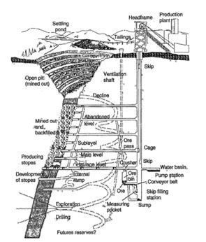
The footwall and hanging walls are not labeled, but I am sure you can identify them after our previous discussion. The answer to the question of why the permanent structures such as the shaft are located in the footwall side of the deposit is: as areas are mined out within the deposit, it is likely that some caving will occur, and the caving can be a consequence or cause of fractures propagating through the hanging wall, and potentially ending at the surface. If there were any structures such as a shaft in the hanging wall of the deposit, they would be destroyed by the normal mining operation.
You’ll note the main levels versus the sublevels, and don’t miss the decline. Also, take note of the exploration-drilling program that is ongoing throughout the life of the mine.
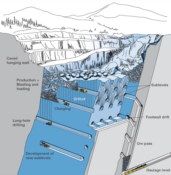
I like the next figure because it shows the footwall drift clearly as well as the sublevels and some of the unit operations within the sublevels. The ore passes down to the haulage level are easy to see in this figure, too.
Finally, this third figure allows me to illustrate and elaborate on more of the terms. In thick-bedded deposits, it is often necessary to mine the bed in multiple steps known as lifts or benches. In this example, they are taking the seam in two lifts, and you can see the work underway on the benches. Specifically, you should be able to identify the locations where they are breast stoping, underhand stoping, and overhand stoping. You can also see the pillars that are being left behind to support the overlying strata.
Now that we have a common vocabulary to describe the elements of underground mines, as well as an understanding of these basic elements, we are ready to look at the underground mining methods. In the next two lessons, we will look at the methods. I think it is useful to put the methods into a context of their usage within the industry. That is to say, some methods are rarely applied, and others are frequently applied. Let’s finish up this lesson by taking a closer look at this.
8.2.4: Prevalence of Underground Mining Methods
8.2.4: Prevalence of Underground Mining Methods
The actual number of underground mines will fluctuate somewhat year-to-year, as a few close and a few open. In recent years, there has been a more significant shift in the number, as several underground coal mines closed due to market conditions. Even though the actual numbers will vary, the proportions are relatively stable. For the purposes of this illustration, we will use underground mines in the U.S., and I’ll round up the number slightly for ease of comparison. There are approximately 600 underground mines in the U.S. Of those, approximately 400 are coal and approximately 200 are noncoal. The noncoal includes metals, industrial minerals, and stone mines.
Every one of the 400 coal mines utilizes the room and pillar method, neglecting the 2 or 3 underground anthracite mines that employ a hybrid method. All of the other underground mining methods are distributed among the 200 noncoal mines. Let’s look at that group in more detail.
| Unsupported Methods | Supported Methods | Caving Methods |
|---|---|---|
| Room and Pillar (150) | Cut and Fill (including sub-methods/variations (23) | Block Caving (2) |
| Shrinkage Stoping (2) | Sublevel Caving (0) | |
| Open Stoping (including sub-methods/variations) (18) | Longwall (all of the longwalls, coal and noncoal, are in mines that use room and pillar for the development of the panels) |
The disproportionate number of room and pillar mines is quite noteworthy. Roughly 75% of the underground noncoal mines employ this method. If you add the coal mines into the mix, roughly 90% of all underground mines are using the room and pillar method. Let me ask you a question. If you were to become an expert in the design of one mining method, which would you choose? Well, certainly your career options would be much better if you chose room and pillar! This is not to say that you don’t need to learn about the other methods! You do!!! However, in our curriculum, we do emphasize this method more than the others, and now you know why!
Let’s look at the commodities mined by the three most prevalent methods: room and pillar, cut and fill, and open stoping; as well as the two rarely used methods (in this country) of shrinkage stoping and block caving.
| Method | Commodity | Number |
|---|---|---|
| Room and Pillar | Limestone & Gypsum | 105 |
| Salt | 16 | |
| Lead/Zinc | 12 | |
| Trona | 5 | |
| Potash | 4 | |
| Silver/Gold | 3 | |
| Copper | 1 | |
| Open Stoping | Gold | 9 |
| Zinc | 7 | |
| Nickel | 1 | |
| Platinum | 1 | |
| Shrinkage Stoping | Gold | 2 |
| Cut & Fill | Gold | 19 |
| Silver | 2 | |
| Platinum | 2 | |
| Block Caving | Molybdenum | 2 |
Please be aware that not all commodities are accounted for in this table. There are additional industrial minerals mined by an underground method, which are not accounted for in this data. Despite the very small discrepancies in the totals, the data illustrates accurately the prevalence of the mining methods by commodity.
Review your knowledge of Module 8 terms by engaging with the interactive activities.
Lesson 8.3: Mining by Unsupported Methods
Lesson 8.3: Mining by Unsupported Methods
You will recall from Lesson 4.3 of Module 4 that underground mining methods are traditionally placed into three classes: unsupported, supported, and caving methods. These classes reflect the competency of the orebody and host rock more than anything else. If you excavate an underground opening in the ore or the rock is the opening stable -- i.e., will it remain open for an extended period, or will it begin to fall in? If it is unstable, i.e., the surrounding ore or rock breaks up and falls into the opening, how much support would be required to keep the opening from caving in? The answers to these questions lead us to choose mining methods from one of the three classes.
We are going to focus on the class of unsupported methods in this lesson. If the rock is essentially self-supporting and only requires the addition of minimal artificial supports to achieve a stable opening, then one of the methods from the unsupported class will most likely be applicable.
The three important methods within this class are room and pillar, shrinkage stoping, and open stoping. After a brief summary here, we’ll look at each in more detail. We will not talk in detail about the unit and auxiliary operations associated with these methods, as these were covered earlier in the course. Suffice it to say that a conventional mining cycle is used for shrinkage stoping and open stoping, whereas both continuous and conventional cycles are employed with the room and pillar method, depending on the commodity being mined. Examples of commonly used equipment will be noted for the different methods.
Room and Pillar Mining
This method of mining is used to recover bedded deposits that are horizontal or nearly horizontal when the orebody and the surrounding rock are reasonably competent. Parallel openings are mined in the ore, i.e., rooms, and blocks of ore, i.e., pillars, are left in place to support the overlying strata. Other than the pillars, little artificial support is required and often consists of bolts placed into the overlying strata to pin the layers together, making them behave like a strong laminated beam. A few examples of commodities mined by this method include coal, lead, limestone, and salt. Historically, if the pillars were irregular in size and placement, which is more likely to occur in certain metal and nonmetal deposits, this method was known as stope and pillar, rather than room and pillar. You will still hear the word stope and pillar being used, but the distinction is now largely irrelevant. This method accounts for the vast majority of all underground mining in the U.S. – and I believe globally as well, although I have not done that analysis. Examples of commodities mined by this method include coal, limestone, salt, trona, lead, and potash.
Shrinkage stoping
Shrinkage stoping is used to recover steeply dipping orebodies when the ore and host rock are reasonably competent. A stope, i.e., a large section of the mine where active production is occurring, is mined, but the broken ore is not removed, but rather is left in place to support the walls of the stope until the time when all of the broken ore will be removed. Since rock swells, i.e., increases in volume when it is broken, it is necessary to draw off some of the broken ore as the stope is progressively mined. The name of this method derives from this drawing off or shrinkage of the stope. A modern and important variant of this method is known as vertical crater retreat (VCR) mining. A few examples of commodities mined by this method include iron and palladium.
Open stoping
This type of mining is used to recover steeply dipping orebodies in competent rock. The ore is removed from the stope as soon as it is mined. Sublevel stoping and big-hole stoping are the important variants in use today. A few examples of commodities mined by this method include iron and lead/zinc.
8.3.1: Room and Pillar Method
8.3.1: Room and Pillar Method
Room and pillar mining is arguably the most important underground mining method in practice today. The majority of underground production comes from room and pillar mines, and the majority of underground mines, by number, employs the room and pillar method! Think about that!
Let’s start out by looking at this sketch of a section in a room and pillar mine. Immediately, you can see that only part of the deposit is mined. Openings are driven in the direction of mining, as shown, and unmined pillars are left in place to support the overlying strata.
Remember from our earlier discussion of ground control: when we mine an opening, the weight of the overlying strata must be supported; otherwise, it will cave. As long as the rock layers over the opening are sufficiently strong (think beam), the weight of the overlying members will be transferred to the points where the beam is supported. Those points are the pillars. And from an engineering perspective, it is essential that you do not make the beam too long, because if you do, the beam will fail in the middle, and you will have a cave-in. Just to make it more interesting, you should know that in addition to choosing an appropriate opening width, which is governed by the allowable span of your beam, you also have to worry about the pillar. In some cases, the pillar is not strong enough to bear the weight being superimposed on it, and it will fail. And, in some cases, the pillar will be sufficiently strong, but the layers comprising the floor will not be, and the pillar will push through the floor. Lots of things to think about! This is one reason why, if you are going to be a mining engineer, you will take a course in rock mechanics and cover ground control design in the underground and surface mining courses.
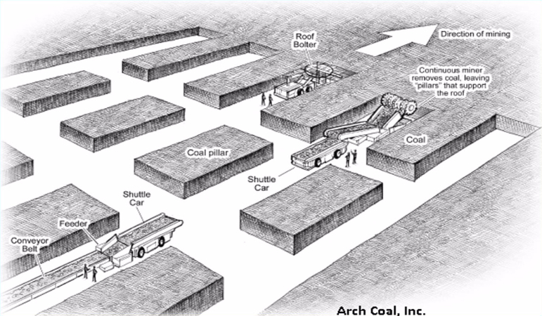
Anyway, back to our sketch of the room and pillar section. The diagram shown is labeled specifically as a coal mine. In fact, it could just as well be salt, trona, lead, and so on; but with some differences that we will discuss. The active mining areas of coal mines are known as sections. In this diagram, you see one working section. This section consists of the equipment and personnel required to conduct the mining activity. From our earlier discussions of unit and auxiliary operations, you will recognize this as a continuous mining operation; and in the U.S., there are no remaining conventional mining sections in underground coal mines.
The mined-out areas in the sketch are given special names, and these may vary depending on the type of deposit that is being mined. There is one term of special significance: the mined-out areas in the direction of mining are known as rooms. Hence, the name of the mining method, room and pillar. Very clever… Typically, the pillars are laid out in this regular checkerboard pattern in coal mines, and now in most other commodities as well. That was not always the case for the noncoal mines. The size, spacing, and even location of the pillars would vary significantly, as would the dimensions of the openings. In those mines, the method was known as stope and pillar. Although you will still hear the term being used, the distinction has largely disappeared, and the term room and pillar is normally applied across all deposit types employing this general method. As a point of interest here, I would mention that mining engineers now recognize that there are serious shortcomings to the somewhat random placement of pillars, resulting in unnecessary ground failures, e.g., cave-ins. As a result of the art and science developed in underground coal mines, ground control approaches such as the pressure arch approach are more generally applied in all commodities, and this results in a more uniform placement of pillars. You will learn more about this if you take a rock mechanics course.
I want to talk about a few more terms. We’ve defined rooms and pillars. The openings driven between rooms are known as crosscuts. Here, they are shown at an angle of 90 degrees, and that is common; but if you are using continuous haulage, such as the flexible conveyor trains that we covered earlier, then you’ll be driving the crosscuts at a different angle of say 60 degrees. Recall also, that the point at which the material is being freed from the deposit is known as the face. In the sketch, you can see five faces. The continuous miner is mining at one face, and a roof bolter is bolting at another face. Alright, there are just a few more terms, and then we fill in some additional detail for the method itself. Let’s look at this plan view of a room and pillar section.
The sequence of rooms in the direction of mining is known as an entry in a coal mine. They take on the appearance of well-laid-out streets in a city. Indeed, you can stand in an entry and see for quite a distance. If you are in a noncoal mine, you may refer to entries as well, but more likely you’ll call them drifts or headings. What about the sequence of crosscuts? What special name do we assign to that? We don’t assign a special name, and the primary reason is that they do not form a continuous path in the way that rooms do for entries. The reason for that will become clearer within this lesson.
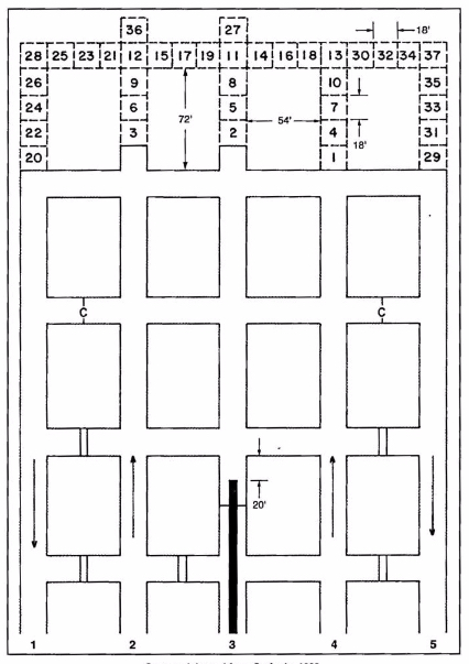
The collection of rooms and pillars shown in this figure form a panel. In this case we have a five-entry panel. Depending on the mining plan this panel could be 10,000’ or more in length, but its width will be determined by the width of the pillars and entries. Three-entry panels are common, as are four and five. There are additional details of note on the plan view.
- There are two different symbols, which appear in the cross cuts: the double line is a solid barrier known as a stopping, and often constructed of concrete blocks; and the single line with a “C” is a flexible curtain, known as a check curtain. Both of these are used to route and separate ventilating air. Recall that you need to provide fresh air to the working places, and then you need to exhaust the air that has become fouled with dusts and gasses.
- The directional arrows are illustrating the direction of the ventilation streams, sometimes called air courses. The air moving toward the face is known as the intake, and the stale air that has already passed the working face is known as the return.
- The thick solid line in entry number three is the conveyor belt.
- The numbered blocks are representing a cut sequence, i.e., block 1 is mined and then block 2, and so on. The cutting sequence will vary by mine, so you don’t need to know this cutting sequence. Simply, it is illustrating that there is a pattern to be followed. This pattern will be designed to optimize productivity and safety.
- The dimensions that are shown will vary somewhat by mine and certainly by commodity; and again, you don’t need to remember these specific numbers.
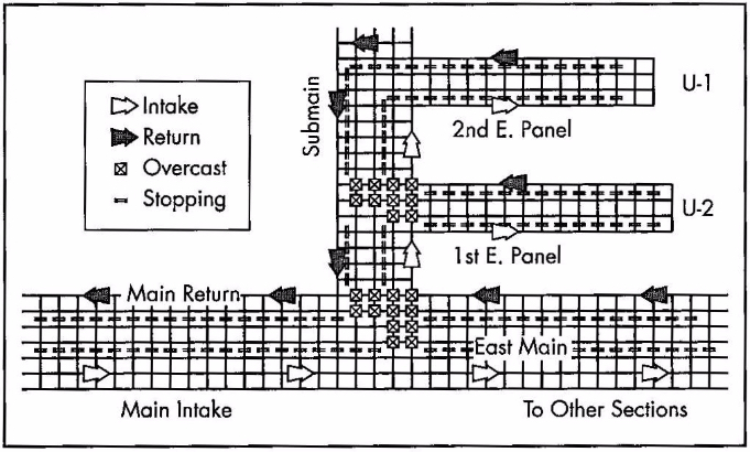
Finally, in terms of this overview, let’s look at this next figure. Notice that we are no longer representing the entries and cross cuts the same way. We’ve replaced them with a single line. That makes it easier and faster to draw these diagrams. As you look at this figure, you will see some of your newly acquired concepts, including Panels, Sections, Intakes, Returns, and Stoppings. There are also three new terms: overcasts, mains, and submains. Overcasts are yet another type of ventilation control joining curtains and stoppings as controls to route ventilating air. Specifically, overcasts are used to route on type of air over tip of another. It’s similar to a pedestrian overpass to allow people to walk over top of a busy highway. The overcast allows us to route, for example, intake air over top of a return aircourse without mixing the two airstreams. To satisfy your own curiosity, go ahead and trace the airflows in the part of the mine represented in the figure.
Now, on to the two other terms that I really wanted to highlight in this figure: the mains and submains. These are common terms in every coal mine and in some industrial mineral mines, e.g., trona. These words are simply designating their importance in the overall mine plan. The mains serve as the primary means of distributing utilities throughout the mine as well as being the location for the primary transportation and materials handling routes. The submains branch off of the mains to provide these same services to a group of panels, and the panels of course are the location for the active production sections. These word, mains and submains, and sometimes panels, are used as adjectives as well as nouns. The major aircourses supply air for the mine are known as the main intakes and main returns, for example. Main haulage of the mine may be a 72” belt, whereas the belts in the submains may be 60”, for example. It is no coincidence that the mains have more entries than the submains, which usually have more entries than the panels. Mains with seven to eleven entries are common. Often, three or four parallel entries are required to serve as intakes in larger mines, with two or three parallel returns, and another two isolated entries for material handling -- one being a belt entry and the other a track (rail) entry.
We now have a basic understanding of the layout for room and pillar mines, and we know the key terms that are used to describe them. We also know either continuous or conventional production cycles can be employed. With this as a solid foundation, let’s complete the picture with the conditions necessary to use a room and pillar method.
This is an underground method for which you can find mines as shallow as 60’ and at depths of greater than 2500’, and so we can conclude that depth is not a particular defining characteristic for the use of this method. The method does require tabular deposits, as opposed to the porphyry or vein deposits; and further, the method requires that the ore be fairly uniform in quality and thickness. Those are defining characteristics. Deposits with little dip (< 15) are necessary, and less dip, the better. There are rare examples of room and pillar being applied to steeply pitching (dipping) coal seams, but they need not concern us at this time. The rock strength needs to be moderate to strong. The rock needs to be strong enough to allow a reasonable span of opening between pillars. The ore strength on the other hand is not quite as important in the choice of the method. As the ore strength declines, it will be necessary to leave larger pillars, and at some point, that becomes uneconomical. In real-world situations, however, the ore strength is rarely an important characteristic for the selection of this method.
Before reading on, please pause for a minute and think about the characteristics that will lead you to select or exclude the room and pillar method from consideration. Specifically, think about the relationship between that characteristic and the design or operation of a room and pillar mine.
I identified the shape of the deposit as important in the selection of this method, and I said that uniform thickness is desirable. In fact, the thickness can vary by 10 or 20%, and not eliminate room and pillar as a viable method. In some cases, the quality of the ore declines rapidly as you approach the interface between the ore and host rock. In those cases, it is not unusual to leave anywhere from several inches to several feet unmined. In still other instances, the competency of the rock in the immediate roof may be very poor, and in those cases, that material will be mined along with the ore. Yes, that will dilute the run-of-mine product, but the additional cost of doing so, may be less than the cost of the ground-control problem that would result from attempting to leave the “bad” roof layer in place.
I did not say anything about the thickness of the orebody. Room and pillar is used successfully in deposits as thin as 24” and as thick as 100’ or more. It is clear that the orebody thickness is not a defining characteristic of the method itself. However, the mining plan and cycle will be affected as the thickness increases. Consider this: you have a continuous miner with a reach of say 15’. Your seam is 25’ thick. How you are going to mine that seam? Are you going to take 15’ out of the 25’, perhaps down the middle, and leave the remainder? Although there might be an instance in which you would do that, generally you would not invest the capital to access the orebody, and then voluntarily leave a lot of it behind! So, back to the question… what are you going to do?
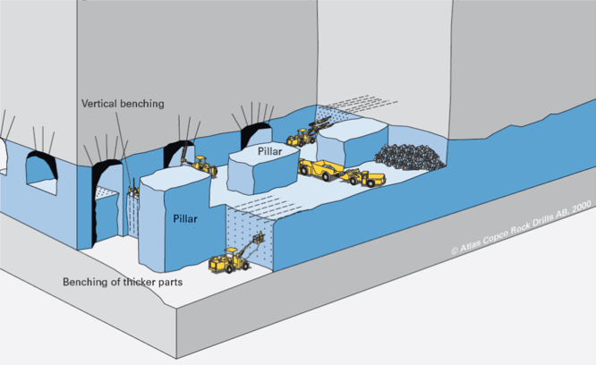
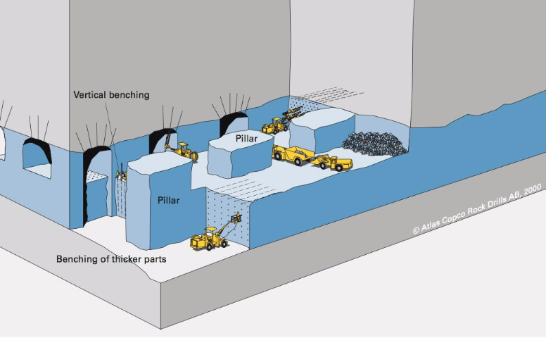
Why not take it out in layers? That is what we do, and we refer to it as benching. We can do this, and it is frequently done with the continuous or conventional cycles. In some instances, both are used, i.e., the top lift or bench is taken with a continuous cycle and the bottom bench is taken with a conventional cycle. In these thicker seams, three of more lifts may be taken. Take a look at this figure.
It is apparent that the first bench is taken at the top of the deposit. This is the norm for room and pillar mining. For one thing, it is easier to scale and bolt the roof form this first bench. This figure is illustrating a conventional cycle, and we can see a couple of interesting practices. Note the drifting or breast stoping occurring on both the top bench and on the lower bench right side. As a contrast, look at what’s happening on the left side and front of the top bench: underhand stoping. They are also showing some overhand stoping, but, to be honest, I have no idea why! If they were moving upwards in the orebody that would make sense… Just ignore that part of the figure! Anyway, this is a good example of benching used in room and pillar mining.
A defining characteristic for the selection of the room and pillar method, as I explained earlier, is a relatively flat lying deposit. What if you meet the characteristics of the unsupported class of methods, except that you have a steeply dipping orebody? You will look more closely at selecting an open stoping or shrinkage stoping method. Next, we will look at these two unsupported methods that are only applicable to steeply dipping deposits that are greater than 50 degrees, and frequently near vertical. The dip angle of the footwall must be greater than the angle of repose for the broken ore because these methods depend on gravity flow to collection points (draw points).
8.3.1a: Typical Equipment
8.3.1a: Typical Equipment
Before moving on to look at the methods suited for these steeply dipping deposits, I do want to identify some typical equipment used in room and pillar mining. There is a significant variation in equipment usage across room and pillar mines. This should not surprise you, given the big differences in the deposits. As you might expect, the equipment used to mine a 5’ thick coal seam is quite a bit different than that used to mine a 50’ thick lead-zinc deposit.
| Continuous Cycle | Conventional Cycle |
|---|---|
| Continuous mining machine | Jumbo drill |
| Road header | Wheeled loader |
| Shuttle car | Haul truck |
| Flexible conveyor train | Mine truck |
| Roof bolter | Scaler |
| Roof bolter | |
| Powder loader |
In the list of “typical” equipment, you saw an item that has not been discussed yet. A rock duster, which is an essential piece of equipment for an auxiliary operation in underground coal mines. Given the importance of this auxiliary operation to underground coal mining, let’s say a little more about the need for it, and the practice of rock dusting.
After we conclude our discussion of rock dusting, we’ll resume with the unsupported methods of shrinkage and open stoping.
8.3.1b: A Practice and the Auxiliary Operation to Prevent Explosions
8.3.1b: A Practice and the Auxiliary Operation to Prevent Explosions
Fine dust that is suspended in the air can be very explosive. Coffee, coal, cotton, and flour are important examples of dusts that are explosive, and are examples of deadly explosions that do occur in industrial settings. Many processes that involve milling, grinding, and cutting, for example, can generate fine dust particles. Under the right conditions, they can fuel powerful explosions.
Fine basically means that the dust particle has a very large surface area to volume ratio. We all have practical experience with fine dust. If there is sunlight shining into your room, pick up a towel, sheet, or piece of clothing and shake it. What do you see? Dust particles floating in the air, right? Eventually, those dust particles settle onto your desk or other furniture, and then periodically you take a cloth a wipe the accumulated dust away. There are corollaries between your practical experience and the industrial issue with dusts, and we will identify them.
The dust particles that are suspended in the air, and then eventually settle are known as float dust. The exact size of the float dust is somewhat dependent on the material. For coal dust, we are interested in particles that are 75 microns or less in size. The cutting action of carbide-tipped bits, as used in continuous mining machines, and shearers, creates not only large pieces of coal, but also a range of much smaller particles. Some of these are less than 10 microns and are respirable, i.e., they are trapped in the lungs when we breathe air containing these particles. Long-term exposure to excessive concentrations of respirable dusts will lead to fatal lung diseases, e.g., black lung (coal) or brown lung (cotton). The concentration of respirable dusts is heavily regulated, and engineering controls are used to ensure that hazardous concentrations do not occur. As we’ll see, the concentration of float dust is regulated as well. The creation of these dusts is an unavoidable consequence of the cutting or processing of the materials. Therefore, if we want to avoid bad outcomes, we have to take steps to ensure that the dust does not cause harm.
Before we can mitigate the affects of float dust, we need to know a little more about the genesis of dust explosions. In general, we must satisfy three conditions to have an explosion. We need a fuel, an oxidizer, and an ignition source. In this case, the dust serves as the fuel and the oxygen in the air serves as the oxidizer. Ignition sources can be varied. A spark created when a carbide bit strikes a hard rock at the interface of the coal seam and the roof, a spark from a motor or piece of electrical equipment, or in the old days, a match used to light a cigarette. It takes a very small amount of energy to ignite a dust cloud, or for that matter, a methane-air mixture. Given this information as background, what can we do to prevent a dust explosion?
Well, we have three choices, don’t we? Eliminate the fuel, the oxidizer, and/or the energy source. We can’t eliminate the oxygen, because it is in the air that our miners are breathing. We can’t eliminate the fuel, or can we? We can eliminate the energy source, so let’s talk about that one first.
We can ban the use of smoking materials in the mine or plant. In coal mining, smoking was banned with the 1969 Coal Mine Safety Act. This eliminated many explosions in coal mines. Next, we can mandate the use of special electrical equipment. We can require that all electrical equipment used in certain areas be placed inside of explosion proof enclosures. Unfortunately, no one has devised a way to prevent frictional ignitions, i.e., when a cutting bit creates a spark when striking certain rock masses, such as quartz or pyrites. Dramatically reducing the likelihood that an energy source will exist is doable; but guaranteeing that there will never be an energy source is not. Therefore, we have no choice but to try to eliminate the fuel source. While it is impossible to complexly eliminate the fuel source, we can dramatically reduce the chance of satisfying the three concurrent conditions necessary for an explosion, if we dramatically lower the likelihood of two of the conditions.
We cannot stop the generation of float dust, although researchers are attempting to devise ways to control it at the source. We can take two important steps after it has been created. Before talking about those steps, let’s first look at the anatomy of a dust explosion; and I need to preface that discussion with this fact: dust explosions follow from a methane explosion. We will use that as our starting point.
- A small volume of methane is ignited, perhaps by a frictional ignition. 99.999% of the time, our properly engineered and operated ventilation system is diluting the gas as it is liberated during cutting, and the ignition amounts to no more than a “little pop and flash of light.” If there is a little more methane present, the initial ignition will grow in size. High temperatures are produced and the gas and surrounding air will rapidly expand. The force of this explosion and the attendant damage will depend on the volume of methane present. We take significant steps to prevent the presence of an explosive mixture of methane and air, but sometimes multiple people fail to perform their responsibilities, and the unthinkable happens.
- The rapidly expanding gases create a shock wave, which produces a wind out in front of the fireball. The fireball will dissipate as soon as the methane is consumed, and the damage could be confined to a relatively small area; unless another fuel source is present. Any guesses on the other fuel source? Yes, accumulations of float dust.
- The traveling shock wave “stirs up” and dissipates accumulated float dust. A moment later, the fireball comes through and ignites this dust cloud, producing a violent explosion. At this point, the explosion may transition from a deflagration to a detonation. When it detonates, the shock wave will be moving faster than the speed of sound! The propagation of the explosion at this point does not require any methane – only dust. The moving explosion will entrain float dust and essentially at that point, it is carrying its own fuel! Even if it reaches a point where there is no float dust, there will be sufficient fuel entrained to allow propagation over a considerable distance. And, of course, if additional dust is encountered, the explosion will continue that much further. The amount of energy involved, as you might imagine, is staggering. A dust explosion can travel over miles and miles of entries, leaving nothing but twisted metal and charred remains in its path.
If you were standing downstream of a mine explosion, you would see the flame front approaching at a speed in excess of 1200 ft./sec. You can see the effect of the shock wave out in front of the flame front.

Often, these explosions will ultimately vent to the outside. Here is one such event – a research experiment, not an operating mine explosion, at the U.S. Bureau of Mines’ experimental mine near Pittsburgh. Much of what is known about these explosions and their prevention was developed by researchers at this facility.
Fortunately, these explosions are rare in the U.S. The last coal dust explosion occurred in 2010. You have to go back four decades to find the one before that (actually there were a few smaller gas explosions during that period as well). Unfortunately, they have not been eliminated.
So, what more can we do to prevent these horrible events? Hopefully, this more detailed explanation of explosions has given you an idea or two! What do you think?
First off, we need to clean up accumulations of float dust. In fact, the law requires such cleanup to occur, and you will be fined if an inspector finds excessive accumulation of float dust. This is a very important “housekeeping” function. While you can successfully cleanup float dust accumulations near belt drives and along the belt line, it is impossible to prevent fine layers of dust from accumulated on the mine ribs and floor. Consequently, we need another approach, and that is the application of rock dust, which is known as rock dusting. We apply rock dust with rock dusters. I admit these terms are not very imaginative, but at least they will be easy to remember!
What is this rock dust and why is it effective? Rock dust is usually limestone that has been crushed to a fine powder. When we rock dust, we are applying, and literally blowing, this powder onto every surface in the coal mine. What purpose does this serve? Well, first off, this dust is inert, i.e., it is not combustible. Let’s assume that we’ve applied rock dust to all surfaces, and with this practice in place, let’s revisit the propagation of the explosion.
As explained previously, the shock wave moving ahead of the flame front disperses any dust into the air, and then the flame front ignites the dispersed dust cloud, and the explosion continues to propagate. But, what if the dispersed dust were an inert material like rock dust? Two good things would happen. First, the explosion would be deprived of new fuel, and second, the mass of the rock dust will reduce the temperature of the flame front. The net effect is that the explosion is quenched. Thus rock dusting can prevent dust explosions; but only if it is applied in sufficient quantity. Based on NIOSH research, MSHA regulations require that sufficient rock dust be applied so that the resulting mix of float dust and rock dust contains a minimum of 80% of inert, i.e., incombustible, content. Rock dusting is an essential and critical auxiliary operation in coal mining, and the law requires that all areas within 40’ of the active mining face be rock dusted.
You may be interested to know that you cannot use just any rock dust for this purpose. The law defines the specification for rock dust as follows:
Pulverized limestone, dolomite, gypsum, anhydrite, shale, adobe, or other inert material, preferably light colored, 100 percent of which will pass through a sieve having 20 meshes per linear inch and 70 percent or more of which will pass through a sieve having 200 meshes per linear inch; the particles of which when wetted and dried will not cohere to form a cake which will not be dispersed into separate particles by a light blast of air; and which does not contain more than 5 percent combustible matter or more than a total of 4 percent free and combined silica (SiO2), or, where the Secretary finds that such silica concentrations are not available, which does not contain more than 5 percent of free and combined silica.
I am not going to test you on the specific details of this definition, but I thought that you might be interested to know the standard.
Rock dusters come in a variety of shapes and sizes, but consist of a storage vessel for the bulk rock dust, a feeder, and a compressed air system to entrain the rock dust in an air stream. Application can be through hoses directed by a miner or broadcast in all directions around the rock duster. In some instances, it is desirable to apply rock dust continuously, and in those cases, trickle dusters dispense a small but continuous stream of rock dust into the air stream. This is done, for example, in certain return aircourses and belt entries.
One of the most surprising sights to people going into a coal mine for the first time is that the mine is white rather than black! Rock dusting is the reason for that!
It’s tough to find a really good video illustrating rock dusting. This one here (2:53) does a reasonably good job at the 2-minute mark; and the other operations that you can see in this clip are worthwhile watching as well.
Ok, let’s continue with our study of unsupported mining methods!
8.3.2: Shrinkage Stoping
8.3.2: Shrinkage Stoping
Shrinkage stoping is a vertical stoping method, conducted in a vertical or near-vertical plane, and at an angle greater than the angle of repose of the broken ore. A defining characteristic of shrinkage stoping is that most of the blasted (broken) ore remains in the stope to support the hanging wall and footwall. However, when ore is broken, for example by blasting, it swells, i.e., its volume increases. This swell may be as much as 30% or even more. Therefore, as mining progresses within the stope, it is necessary to draw off some of the broken ore – to make room for the next round of drilling and blasting as well as to create space for the next slice of ore to be blasted into. This drawing off was known as shrinking and hence the name associated with this method: shrinkage stoping.
Let’s take a closer look, using the following figure.
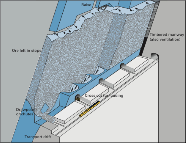
Although not shown, a shaft has been sunk on the footwall side of the deposit, and among other development workings a haulage drift has been driven, and then crosscuts into the orebody. Next, draw points and chutes were constructed by drilling and blasting in exact patterns. Then, the orebody within this stope is undercut. Raises are constructed at each end of the stope to provide manways for personnel access (ladders) as well as to provide ventilation and utilities, such as compressed air lines. This is a very labor-intensive method.
As an overhand stoping method, holes are drilled, loaded, and shot. A portion of the broken ore is drawn off to create sufficient space to allow the drilling and blasting operations in the stope. Once the newly drilled holes are drilled and loaded, the miners and equipment will be withdrawn. At that time, an additional portion of ore will be withdrawn to create sufficient space to account for the swell of the ore that will be blasted. Once this has been done, the round will be fired. Then a portion of the ore will be withdrawn to create space for the overhand stoping to continue. However, before the drillers re-enter the stope, any required ground control will be taken care of. Given that the ores are usually strong, little ground control will be required, other than scaling any loose materials. After it is safe to re-enter the stope, the cycle will repeat.
All right, let’s fill in some additional detail. First of all, why are we leaving ore in place? Essentially to keep the hanging wall and footwall from closing open stope, and causing a failure. Typically, the ore is strong, but the country rock, less so. This method works well with narrow veins, as thin as 3’ or thicker veins of 100’ or so. Stope lengths vary from 150’ to 300’ and heights of 200’ to 300’. In narrow veins, the stopes are laid out longitudinally, whereas in thicker veins they will be transverse. The key design parameters in shrinkage stoping are the dimensions of the stope, largely governed by the size and shape of the deposit. Although rock mechanics will enter the picture in determining size of the stope, the openings used are generally relatively small and are not excessively stressed. Therefore, the major concern is to maintain a manageable-sized stope that ensures a smooth flow of ore by gravity and effective draw control.
A high-quality ore, i.e., high grade and a valuable commodity, is necessary given the high cost of this method. It is labor intensive, and productivity is low compared to other methods. Furthermore, the ore needs to be uniform in quality, as the method doesn’t lend itself well to blending. There are a few other characteristics of the ore that are important. When blasted, the ore should not pack – if it does, you won’t be able to draw it off, and secondary blasting may be required. The ore may remain in the stope for six months to a year, and during that period it should not oxidize, as oxidation can create mineral processing problems, or worse, spontaneous combustion can occur, creating a carbon monoxide and fire hazard.
This method in its original form, as described here is, is unlikely to be used anymore. The last mine that I am aware of in the U.S. was a platinum/palladium mine in Montana. Despite the advantages of this method, it has two really serious disadvantages: one is safety and the other is productivity. Miners working in the stope after each blast presents a level of risk to their safety that cannot be justified by modern standard. From a productivity perspective, there are multiple problems. It requires the use of small equipment and multiple miners. The working surface for the miners is the blasted ore, which makes it difficult to move equipment. Given these serious limitations of the method, you should be asking yourself the question: why are we bothering to talk about this method? As it turns out, there is a modern variation of this method, which is quite successful, and accordingly, quite popular. The variant is known as the vertical crater retreat (VCR) mining method. It was invented by mining engineers working in the nickel mines in Canada. The company, INCO or International Nickel Company as it was known, obtained a patent on the method, and until the patent expired near the end of the 20th century, INCO had exclusive use of this new method.
Vertical Crater Retreat (VCR)
As a variation of shrinkage stoping most of what we said there, applies here, except for the differences that I am going to point out to you now. VCR is much safer because miners and equipment do not enter the stope, and VCR is amenable to a high level of mechanization. In these two differences, VCR has overcome the two primary disadvantages of shrinkage stoping that we identified. This is all well and good, but how does VCR achieve these two improvements? Let’s take a look at the following figure.
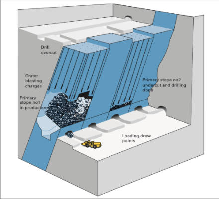
Before going into any detail, I should tell the underlying secret that made VCR possible: significant advancements in drilling technology, and specifically down-the-hole drills. You’ll see why this is so important in a moment.
The initial development of the stope for VCR is the same as for a shrinkage stope. The one addition is the need for an overcut at the top of the stope, for that is where all of the drilling and blasting will originate. Either from the shaft or a ramp, crosscuts will be driven over to the overcut level. The overcut will be mined out, and then this will serve as the location where the miners will work. Rather than being in the stope with the attendant hazards, the miners are on top of the stope working from a stable and safe location.
From the overcut, they will use down-the-hole drills to drill the full length for all of the holes that will be required to mine the stope. Drilling holes of that length, accurately, is difficult. If the position of the holes varies by more than a few percent, the rock fragmentation will suffer. Oversize material will result, and will likely cause serious problems when they try to draw down or shrink the stope. Excessive fines will be produced, and they will likely cause plugging and packing. As such, very accurate drilling technology must be used. That’s where the advances in DTH enable the success of VCR. Of course, DTH is only an enabler. It also took clever innovation in the blasting design, and specifically in the development and refinement of crater blasting.
The drilling pattern is a grid on the order of 12’ x 12’. The hole diameters are on the order of 6”. While there is engineering guidance in the literature for the design of these crater blast rounds, many of the best practices are closely guarded secrets within the companies using this method.
Once the holes have been drilled, the lowest part of each drill hole is charged with explosive. The explosive is detonated, and a portion of the fragmented rock is drawn off to make room for the next blast. The lowest part of the holes is again charged, the blast is set off, and the cycle repeats. Usually the blast would be designed to take off a 10’ slice of ore. The design and execution of the spherical charges is technically challenging, and there is significant art as well as science to a successful application of crater blasting.
As with shrinkage stoping, there is some revenue from the ore that is drawn off during the development of the stope, but the real “payday” comes after the stope has been completely fragmented. Then the broken ore can be drawn off and sent to the mill over a period of several months.
8.3.3: Sublevel (Open) Stoping
8.3.3: Sublevel (Open) Stoping
If we had a stronger and more competent host rock, we could dispense with the need to keep ore in the stope to support the hanging wall as we do VCR mining. Indeed, such deposits do exist, and when they do, we can employ the open stoping method. There are different variations, but essentially, we delineate stopes, and then through drilling and blasting, we slice off segments of the ore, and remove the blasted ore through draw points. We often divide the stope vertically by driving sublevels longitudinally, and then we ring drill with the sublevel, charge the holes, and initiate the blast. The progression of the sublevel blasting is coordinated spatially from sublevel to sublevel, so that the blasted ore from a sublevel is free to fall to the bottom of the stope where it will be drawn off.
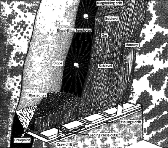
The vertical spacing between sublevels is limited by the accuracy of the ring drills. As with the innovation of VCR, the accuracy of DTH drilling technology led to a variant of sublevel stoping known as big hole stoping. As you can see in the following figure, the ring drilling has been replaced with long-hole drilling. Using DTH drilling the vertical spacing can be increased significantly, and this means less time and cost to develop the sublevels. The holes are typically on the order of 300’ in length and approximately 6” in diameter. A slice of approximately 10 to 15’ is blasted with each round. Ultimately the size of the blast is limited by concerns of blast damage, and as increasing amounts of explosive are detonated, the risk of damage increases.
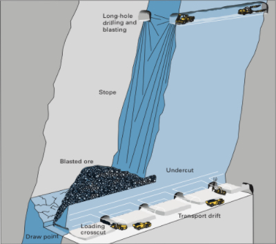
You can also notice in this drawing the vast open spaces created as the stope is mined out. As you recall, a condition for using open stoping is that the host rock be reasonably strong. Here, you can see why this is the case.
In our discussion of shrinkage and open stoping, including the variations of these two major methods, I didn’t say anything about pillars used to separate stopes. There will be a pillar remaining over the entire stope, and this is known as a crown pillar. The pillar underlying the stope is the sill pillar. Finally, there will be pillars separating the stopes transversely, which do not have a special name. Often, there is significant ore of considerable value contained in these pillars. Mining these pillars, however, presents a major challenge: if you attempt to take out the pillar, everything is likely to cave in. It’s rather difficult to recover the ore, if the entire mine in that area has collapsed!
Well, mining engineers are clever, and they have devised means of safely recovering the economic value remaining in the pillars. That’s an interesting story and one that we will tell in the next lesson when we look at cut and fill mining. Stay tuned!
Before moving on to the supported methods, let’s identify some of the equipment commonly found in these different stoping operations.
| Stoping Methods |
|---|
| Jumbo drill |
| Ring drill |
| Down-the-hole drill |
| LHD |
| Mine truck |
| Bolter |
| Powder loader |
Lesson 8.4: Supported and Caving Methods
Lesson 8.4: Supported and Caving Methods
We examined the unsupported class of methods in the last lesson and saw that this class is by far the most prevalent, i.e., those methods account for the vast majority of all mines. Nonetheless, the supported and caving classes are important in those circumstances that match these methods. Let’s examine each class in more detail.
8.4.1 The Supported Class of Mining Methods
8.4.1 The Supported Class of Mining Methods
Supported methods are those that require significant artificial support to maintain stability in the exploitation openings of the mine. We like to use pillars of the original rock mass as the ultimate form of ground control in an underground mine, because they are capable of providing near-rigid support. However, some orebodies are too weak to employ pillars for support. Often, the host rock is not very strong. Pillars are not an option, as a primary means of support, and consequently attempts to remove the ore will likely result in structural failure of the opening. It may not occur immediately, but over the time period that the opening would be needed, failure is likely to occur. Thus, the supported methods are used when production openings will not remain standing during their life. Support methods are also used when surface subsidence cannot be tolerated.
Whoa, but wait a minute. Didn’t we say that caving methods are applicable when the rock caves readily? Ok, then why would we use a supported method, rather than a caving method for these weak orebodies? Good question, for which there are two good answers! One is that caving to the surface will cause a subsidence zone, i.e., the surface will literally collapse and sink by an amount close to the thickness of material removed in the mine. If you are in the middle of “nowhere,” it doesn’t matter. If there are bodies of water, e.g., rivers and lakes, or towns, for example, you will not want to subside them! The second answer to the question is that supported methods can be extremely selective, whereas caving methods are just the opposite.
We could say that the supported class is employed when the other two classes of methods, i.e., unsupported and caving, are not applicable.
The supported class of methods is intended for application to rock ranging in competency from moderate to incompetent, and includes:
- Cut-and-fill-stoping
- Stull stoping
- Square-set stoping
Cut-and-fill and stull stoping is applicable to moderately competent rock, and square-setting is for the least competent rock. Mechanization requirements and labor costs have all but eliminated stull stoping and square-set stoping. Nonetheless, I’ll briefly explain them because it may give you some ideas if you ever want to recover a very small part of the deposit and no other approach is possible.
8.4.1a Cut and Fill Stoping
8.4.1a Cut and Fill Stoping
Cut and fill is a very expensive method, but is very selective. You might predict the type of deposits in which it would be employed as the principal mining method. High value metalliferous ores such as gold or silver are often mined by this, and when the high-grade ore is in veins, the high degree of selectivity of this method is a real asset.
The basic concept of cut and fill is straight forward: we mine a portion of the stope, and then we completely backfill the mined portion. The backfill may simply be broken rock, but more likely is a mix of cement and waste rock. This backfill serves to support the stresses that were originally borne by the ore, and we’ll talk more about the backfill material in a while. Deciding how much ore to recover before beginning the backfilling is an important engineering decision. If you take too much or leave the opening unsupported for too long, it will fail. If you error on the conservative side, your productivity will suffer, and the mining cost will escalate.
So, let’s take a look at one implementation of the cut and fill method. We define a stope by driving an upper and lower haulage level. This defines the height of the stope, and a height of 150’-300’ is typical. The length of the stope is running left to right in the figure below, and may be on the order of 200’-2000’. The width of the stope is going into the page, and in this drawing you cannot tell anything about the width. The width would need to be at least 6’ and may be as much as 100’.
What determines these dimensions? First, you will try to keep your stope within the mineralized zone of the orebody. Second, ground control considerations will prevent you from making the stope too large. Third, the equipment that you are using will require certain minimum dimensions. If the equipment is 8’ wide, then the narrowest dimension of the stope, which is the width, must be greater than 8’.
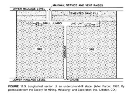
Looking at the figure, you can see the progression of mining activity. This figure is representing an undercut and fill cycle. Drifting or breast stoping is started with the jumbo drill. The holes are charged and shot, and then the LHD loads out or mucks the broken ore, and drops it down the orepass. The orepass is a raise that has been excavated for that purpose, and typically the raise will be protected with a grizzly at the top. This is done to prevent a large rock from plugging the orepass. If that happens, it is very dangerous. Someone has to go down into the orepass to drill and blast the plug. Anyway, as soon as we’ve completed mining the slice of ore, we will begin to backfill. The height of the slice that we take will be determined by ground control considerations, and is likely to be at least 10’ but no more than 30’. The ore will be collected at the lower haulage level and taken out of the mine. It is likely that mine trucks will be used, and there may or may not be a hoist involved in the operation.
Ok, now that you have the basic concept, there are a few variations. The figure illustrates mining moving downward, which we know as underhand stoping, and, in this case, we modified the term cut and fill to undercut and fill. In some deposits, we may choose to mine the orebody in an upward direction, which we know as overhand stoping. In this case, we modified the term cut and fill to overhand cut and fill. Finally, there are times when we progress in small slices, with an ultimate direction of up or down in the deposit; but, in this case, we often call it drift and fill. Don’t stress over the nuances of these terms, but you should already know what we mean by: overhand, underhand, and breast stoping; undercut and fill; and overhand cut and fill.
Here, below, is a deposit in which the ore is so weak that we cannot take a slice across the entire length of the stope, and have to take it in small slices – backfilling each as we go. This is an example of a drift and fill operation.
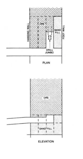
Next, we have a diagram of a modern cut and fill operation with a ramp in place. If you were to go into the underground gold mines in Nevada, for example, you would see mines similar to this. This particular example is using overhand cut and fill, but you will also see undercut and fill in practice there.
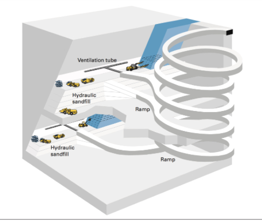
Fill and Backfilling
Significant research has gone into the development of fill materials, the engineering practices to use backfill, and the design of cut and fill mines. Let’s take a closer look at the fill.
Historically, waste rock mined underground, tailings from the prep plant, or rock quarried from a nearby location on the surface were used as backfill. In the former two instances, backfilling serves a secondary purpose of disposing of useless byproducts. Rather than accumulate large mountains of tailings on the surface near the mineral processing plant, we can use them productively in the active mine. Over the years, the practice of adding cement to these raw materials was incorporated into most operations. The addition of cement allows for a stronger backfill to be formulated and placed. It also can be used to provide a smooth working surface. If you are overhand stoping, for example, your equipment will be working from the last backfilled surface. By adding extra cement to this top layer, the equipment and miners will work more productively and safely.
Engineers generally consider three types of fill
- Hydraulic fill: tailings (55 - 70% solids) and 3-4% cement, with a 10% cement mix to top off the fill (smooth hard surface). Pumped underground as a slurry.
- Paste fill: unclassified tailings (up to 88% solids) with only a few percent cement. Requires precise mix and a more expensive plant but offers a stronger backfill and the use (recycling) of a higher percentage of tailings.
- Cemented rock fill: originally waste rock was used to fill the stope, and then hydraulic fill was sprayed on top to form the working surface. Today, the cement is often added at the surface, and then the backfill is dropped down a winze.
You don’t have to memorize these three types, but I’d like you to have an approximate idea of the mix for hydraulic fill.
Here, below is a photo of a paste fill plant, where the tailings are dewatered and mixed with the cement, and then pumped into the mine for placement.
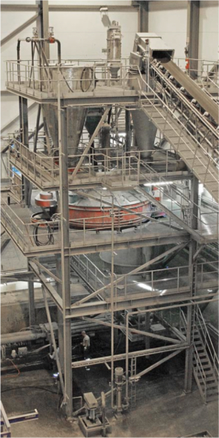
It is important to note that backfill can represent 10 - 20% of the mining cost, and of that cost, nearly 75% is the cost of the cement!
Cut and fill is an important mining method because it enables the recovery of high-value metal deposits in weak rock. The ability to be very selective with this further enhances its usefulness in many of these deposits, in which the spatial characteristics of the deposit require a more selective method. There is another important use of the method, and that is in pillar recovery.
I did mention earlier that often there is a significant value in the pillars that remain after the stope has been mined. In shrinkage stoping or open stoping, the crown and sill pillars as well as the pillars separating the production stopes contain significant ore. But how do you safely recover them? They are there to support the mine openings, and if you attempt to remove them, the openings will collapse. The solution is to backfill the mined-out area around the pillars. Then, with the backfill supporting the weight of the overlying rock, you can safely extract the pillars. Of course, the economics of doing so must be analyzed carefully.
This method of pillar recovery is also practiced in some metal mines employing the room and pillar method. A notable example is in the Viburnum Trend in Missouri – a famous lead-zinc mining region in the U.S. There they have roughly one million dollars of ore tied up in one pillar. Using a cut and fill approach, which is expensive, they are able to recover the pillars profitably.
8.4.1b Square Set Stoping
8.4.1b Square Set Stoping
This mining method was used to mine in the weakest of rock masses. It is extremely expensive, and you’ll see why in a moment, but was used to recover silver and gold deposits through the 1970s in the U.S. The concept of the method is simple: we will mine only a small volume and immediately build and place timbers into the opening to support it on all sides. The timbers will be precisely cut and fitted to form a cuboid. This process will continue indefinitely, resulting in mines with thousands of these square sets. The dimensions of the square set will vary, but 6’x6’x8’ would be illustrative. Take a look at this figure, which illustrates a small portion of a mine with the square sets. The timbers are large, at least 6” square and likely between 8”- 12” or larger. The cost of acquiring such timbers today would be cost prohibitive, but that cost would be small compared to the labor cost to build these square sets. Elaborate and precise joinery was required so that the strength of the square set as not compromised. Today it is difficult to find carpenters with the skill to construct such precise joints! Note in the figure the use of the lagging to keep the weak ground from flowing into the area supported by the square sets.
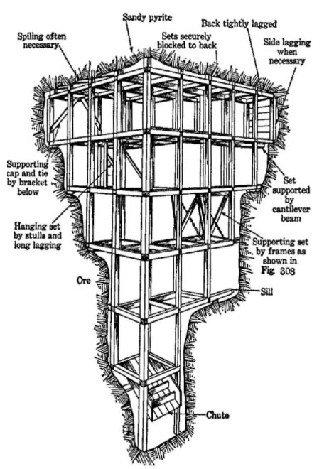
8.4.1c Stull Stoping
8.4.1c Stull Stoping
This method is designed for rock masses that are weak but somewhat competent – not as weak to require square sets, but not sufficiently competent to use cut and fill. The method is also conceptually simple. Place timber posts at close intervals to maintain the opening between the hanging wall and footwall. A serious shortcoming of this method is that the close placement of the stulls effectively prevents the use of mechanized equipment. Hand drilling with stoppers, drifters, or sinkers is required; and load is accomplished with labor-intensive approaches such as slushers, small overshot loaders, and so on. Needless to say, as a principal mining method, this one has also disappeared.

However, with this observation, I want you to consider that you could apply this approach to a very small area of a mine, where you had a unique challenge; and it could be a safe and economic solution to whatever your problem is. Instead of timbers, you might use hydraulic jacks. Regardless, there is value in having an awareness of these older but now obsolete mining methods. This reminds me of another very important point. Just because you select a particular mining method, and then successfully use it for a period of time… don’t think you are required to continue using that method if the conditions are changing. As a mining engineer equipped with knowledge of these methods, do not be afraid to change methods if the conditions warrant, or even to modify a method to suit your needs. The need for this, and the opportunity to do so, is most likely to occur in metal deposits.
8.4.2 Caving Methods
8.4.2 Caving Methods
So far, we have studied mining methods that require exploitation workings to be held open, essentially intact, for the duration of mining. Specifically,
- if the ore and rock are sufficiently competent, unsupported methods are adequate;
- if ore and rock are incompetent to moderately competent, then supported methods must be used.
We will now study a class of methods in which the exploitation openings are designed to collapse; that is, caving of the ore or rock or both is intentional and is the very essence of the method.
We define caving methods as those associated with induced, controlled, massive caving of the ore body, the overlying rock, or both, concurrent with and essential to the conduct of mining.
There are three current methods that are considered to be caving methods:
- Block caving
- Sublevel caving
- Longwall mining
Sublevel caving and block caving have application to inclined or vertical, massive deposits, almost exclusively metallic or nonmetallic.
Longwall mining is used in relatively flat-lying and tabular deposits such as coal, primarily, but the method is used to exploit some noncoal minerals, such as trona.
Longwall mining is a moderately priced method, and sublevel and block caving are among the cheapest of all the underground methods.
The caving class is truly unique because the exploitation openings are deliberately destroyed in the process of mining. Now, having said that, I suppose that before we go any further with this discussion of the caving methods, I should clarify one point. Do not think, even for one second, that because caving is the desired outcome, you are relieved of your engineering obligations for ground control! It is as important to apply rock mechanics to ensure that caving will occur as it is to prevent the occurrence of caving! In effect, the cross-sectional shape of the undercut area (i.e., the width-to-height ratio) must be sufficiently elongated to cause failure of the roof or back. Further, the development openings must be designed and located to withstand shifting and caving ground, as well as subsidence that usually extends to the surface. Thus, there is no shortage of significant ground control challenges with the caving methods. And it doesn’t stop with the engineering. In caving operations, the rate of production may be more important than in many other methods. Specifically, production must be maintained at a steady and continuous pace to avoid disruptions or hang-ups in the caving action.
Let’s take a look at each of the three methods in this class.
8.4.2a Block Caving
8.4.2a Block Caving
This method, which was developed in the U.S. after WW I, is well suited for mining in weak orebodies. Panels or blocks of ore are undercut. Once undercut, the weak orebody begins to cave under its own weight. The caved ore is drawn off through draw points. As the ore is drawn off, the orebody will continue to cave under its own weight. This process will continue until all of the orebody within the block or panel has been recovered.
Under proper conditions, this underground method can rival economically surface mining! It can do so because it is a bulk or high-volume mining method. But it is not a selective method. In the caving and drawing process, you take everything; and therefore this is not a viable method for following rich mineralized zones, for example. If you were in weak ground and you wanted to follow mineralized zones, which method would you first consider? Cut and fill? Yes! The method works well for low-grade ores where you have to mine large quantities cheaply to be profitable. Examples include low-grade copper and molybdenum deposits, diamond-bearing Kimberlite pipes, and certain iron ore deposits, among a few others.
Given the foregoing discussion, let’s summarize the conditions that we expect to see for a successful application of block caving.
- Massive orebody (both horizontally and vertically)
- Low grade ore (the method is not selective)
- Orebody must cave easily into manageable pieces
- block - largest cave volume, weakest ores
- panel - intermediate volume, weaker ores
- mass - smaller volume, weak ores
- The host rock, i.e., the hanging wall has to fracture and collapse, following the cave.
- Subsidence of the ground surface above the orebody has to be acceptable.
Note the breakdown of the orebody into the categories of blocks, panels, and masses. These relate to the size of the cave area. If the ore is very, very weak you can have a wide stope. On the other hand, if you try to have a wide stop with a moderately weak ore, you are likely to get bridging within the stope. Caving stops at that point and it develops into a very dangerous as well as production-killing situation. Thus, the cave volume has to be reduced as the ore becomes marginally stronger. In some mines, they will talk about their panels, and in others, their blocks. Now, you know the reason for this difference in the words they use.
Let’s take a look at a video of block caving before going on. This video will give you a good understanding of the method. The are some other details of note as well:
- Decline and shaft, and the purpose of each
- Ground control measures
- Drawbells
- Undercut level
- Ring drilling
- Materials handling
- LHDs
- Crusher - Orepass
- Conveyor Belt
- Ore skips (hoist)
- Subsidence zone
- Automation
Please watch the following video (3:44) entitled "Block Caving"
Here, below, is a view of a block caving operation, which depicts the information that you saw in the video, but in a slightly different form.
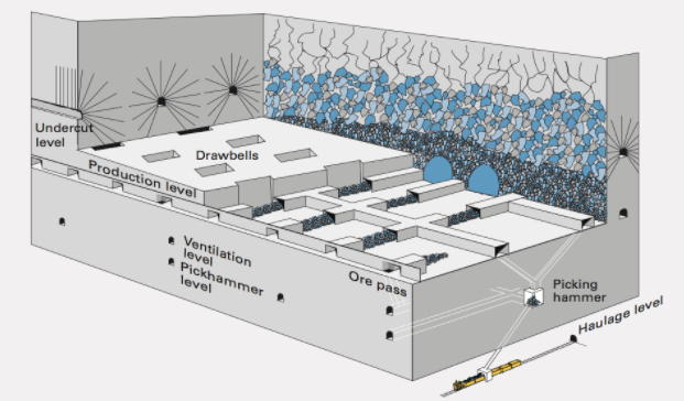
We can summarize what we learned from the video into the following steps for development and exploitation.
Development - Tasks
Development to prepare blocks for production caving is extensive and can take up to several years of advance work. On a per unit cost basis, the development for block caving is no greater than for sublevel caving.
- Sink Shaft and develop decline for access to the orebody from the footwall.
- Drive multiple headings to prepare haulage ways, cross cuts to develop undercut and draw points. Drive other laterals as needed.
- Develop the draw points and ore passes
- Install extensive ground control technologies to stabilize development openings, e.g., shotcrete, cable bolts, steel sets, arches, and so on.
This figure, below, shows these development activities.
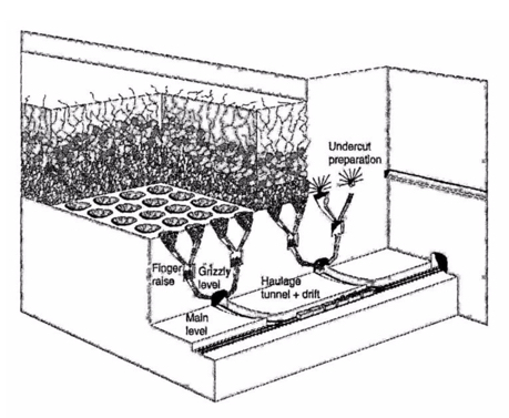
Exploitation - Unit Operations
- Drilling for the undercut using pneumatic- or hydraulic-powered percussion jumbos with a hole size 2 to 3 in.
- Blasting the undercut using ANFO or slurries; and bulk charging by pneumatic loader or pump with electric firing.
- Loading at the draw points with an LHD, or rarely today, a slusher.
- Hauling by LHD from the draw point to an ore pass, and then belt, rail, or truck to a hoist.
8.4.2b Sublevel Caving
8.4.2b Sublevel Caving
Sublevel caving shares many similarities with block caving, with one notable exception, which is responsible for this method: the orebody is competent and will not cave under its own weight. The host rock, on the other hand, is weak and caves behind the ore as it is extracted. Consequently, the orebody needs to be drilled and shot to extract the ore. Once extracted, the hanging wall caves. Given the similarities, we don’t need to say much, and especially if you look at this diagram of a sublevel caving operation, below. There are a few points to be made, however.
You will notice there is no need to develop and undercut, nor bells and drawpoints. Instead, a series of sublevels is developed, and next, the ore above the sublevel is fan or ring drilled. The holes are charged and fired. The broken ore is then loaded out of the sublevel using an LHD (or rarely, a slusher). The LHD’s travel to ore passes where the ore is dumped and then collected at a lower haulage level.
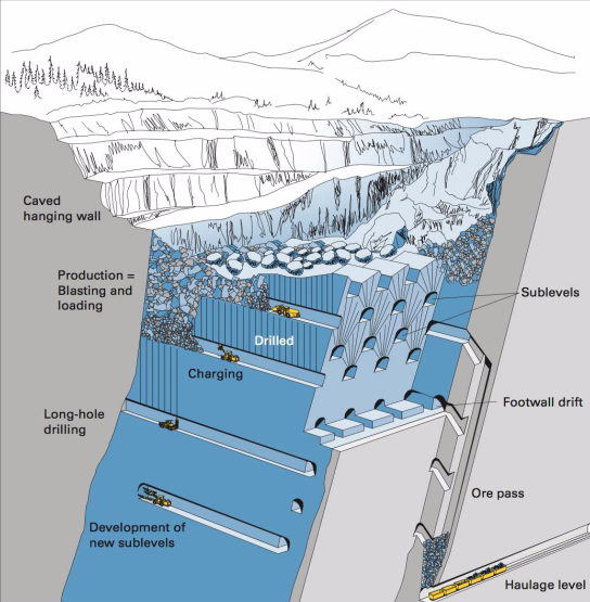
The world’s largest sublevel caving mine is located above the Arctic Circle in Sweden. The Kiruna Mine is mining the Kirunavaara iron orebody. (See figure below.) This mine is famous not only for its size and longevity, but it has been a hotbed of innovation for mining technologies over the years. I really like this figure because it tracks the mine’s development over the decades. You can see that the orebody was mined by open pit for nearly 50 years, and then they went underground. You can trace their progress over the ensuing 50 years up to the present.
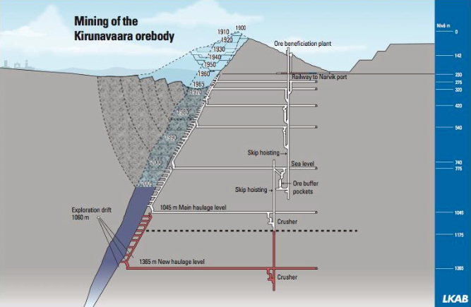
Looking at this next figure, you see the planned workings (sublevels) through 2019.
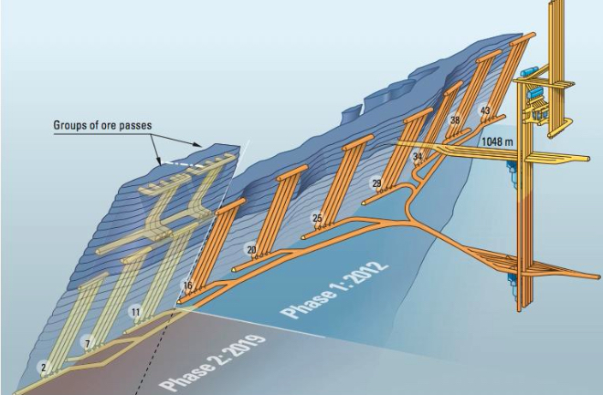
Block caving and sublevel caving require steeply dipping to nearly vertical deposits to enable the gravity flow of the rock. Longwall mining by contrast does not require this gravity flow of the caved material, and as such, it is well suited for tabular and nearly horizontal deposits.
8.4.2c Longwall Mining
8.4.2c Longwall Mining
Longwall mining applies to thin, bedded deposits, with uniform thickness and large horizontal extension. Typical deposits are coal seams, potash layers or conglomerates, trona, and gold reefs. Longwalls are found in nearly horizontal deposits of coal and trona, whereas in metal/nonmetal deposits, a steeper dip is tolerated. The difference is in the equipment that is used. Coal and trona are using massive suites of mechanized and semi-automated equipment that is unsuitable for use in greater than 5-10% grades. There are exceptions, but we’re not going to complicate this discussion with those.
Longwall mining takes its name from the characteristic long face or wall, which may be several hundred feet or more in length. The figure below illustrates this nicely. The ore is extracted in a slice along this long wall. The region adjacent to the face is kept open, i.e., free of obstructions, to allow space for miners and equipment. This region might extend 10’-20’ out from the wall. If we are looking at mining a gold reef, for example, a line of posts will be installed to support the roof or back and protect the active mining activity. At some distance back from the face, caving will be allowed to occur, and in most instances, this is necessary to relieve superimposed loads on the working face. If we are looking at a coal application, the process will be somewhat different. A significant percentage of the coal that is mined underground comes from longwall mines; and not just in the U.S. but around the world. As such, we’ll look more closely at longwall mining in coal.
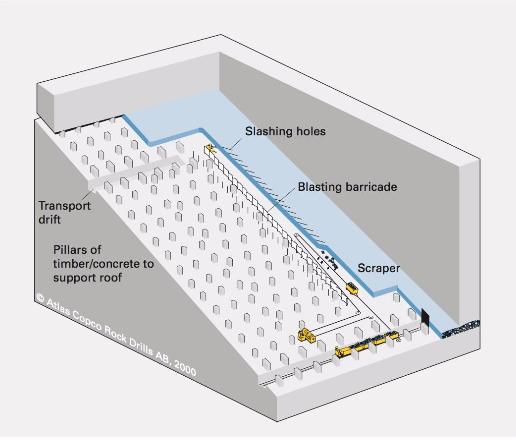
Longwall Mining of Coal
Longwall mining of coal is a high production and high productivity method, employing sophisticated electrical, mechanical, and hydraulic systems, as well as computer-based monitoring and control systems. Most modern (coal) longwall faces are semi-automated. It is noteworthy that longwall operations in trona mines utilize essentially the same equipment and processes that are used in coal mine longwalls. As the long wall or face is mined and the roof supports advance forward with mining, the roof in the mined-out area will cave.
When the panel is initially mined, caving will be delayed. This is a worrisome period because all of the weight of the unsupported roof is transferred to the face and also the gateroad pillars. Sometimes caving may not start for 10 - 20 or more passes of the shearer. If the superimposed load becomes too great, the face and pillars can begin to crush. Thus, for longwall to work safely and productively, the cave must occur in a timely fashion. Once it has started to cave, it will generally continue with each pass of the shearer. Ground control experts will conduct a cavability analysis of the overburden before a decision is made to employ this mining method. This requirement for caving is the reason this method is classified in the caving class of methods.
Please be aware that the longwall panels within the coal deposit are created by room and pillar mining. Thus, many room and pillar (coal and trona) mines are also longwall mines, and in most of them, the room and pillar work is simply to develop the panels and the infrastructure to facilitate operation of the longwall. By that, I mean you need to have a well-developed ventilation, materials handling, and power systems to support a high production longwall. The room and pillar mining creates the mains, submains, and panel entries for these systems. Let’s look at a few figures. These won’t answer all of your questions right now, but these in combination with some videos that will come afterwards, should give you a good understanding of the method.
Let’s start with a plan view of a mine. This figure, below, shows a portion of the mains or submains and the longwall panels. Notice the three-entry gateroads that define the panels. One set of these will be known as the headgate entries and the other as the tailgate entries. The one of the longwall face will be known as the headgate and the other end of the face will be known as the tailgate. The entries adjacent to the mined out panel are the tailgate entries, and that defines the tailgate side of the panel. The longwall face is mined on retreat. That is to say, the gateroads are mined on advance, and then the longwall face retreats back to the submains or mains.
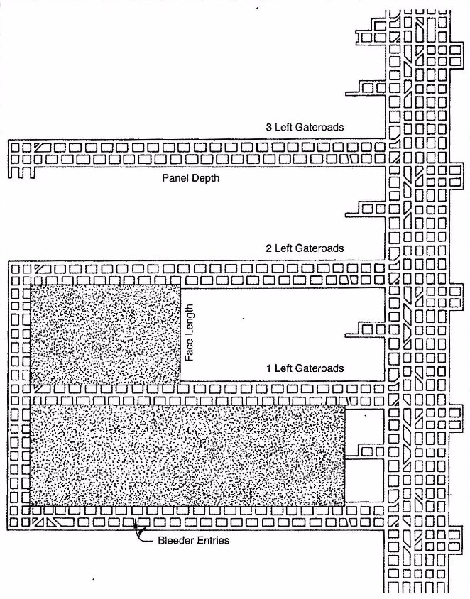
The equipment required for a longwall face is unique to this mining method. Let’s look at it in this figure below, and then when you see it in the videos, it will make more sense.
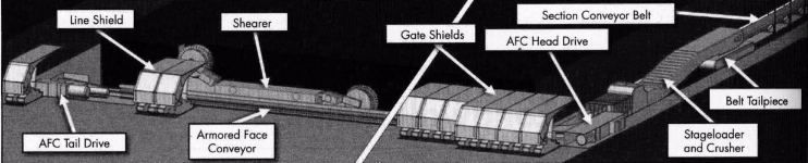
The armored face conveyor is a massive steel structure containing a chain conveyor. The shearer (or plow) rides on the AFC and cuts the coal. The cut coal falls into the AFC, and is transported to the headgate. At the headgate, the coal is crushed to a size suitable for transport on a conveyor belt and then fed at a controlled rate onto the belt. This panel belt feeds the outby belt system. It takes an enormous amount of power (1000s of hp) to operate the AFC, and there are drives at both the tail and headgates to power the chain conveyor. All of this equipment and the miners working at the face are protected by what has been called an umbrella of safety, i.e., the series of shields. As the coal is cut, the AFC snakes into place immediately adjacent to the face. On the right side of this figure, they are depicting this advance of the face, and you can see the shields that have moved into place.
This next figure illustrates more completely the relationship of the longwall panel to the overburden, the gateroads, and the longwall face itself.
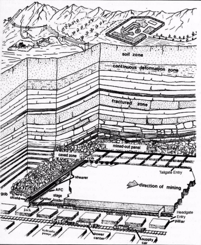
Next, let’s take a look at some videos, each of which is less than five minutes in length. I think these videos are helpful for the details that they show. There are four of them, and they are addressing the same basic topic. However, in each one you can see certain important details more clearly than in the other videos. I suggest that you watch all of them twice, and don’t hesitate to pause them and look more closely at the image. In so doing, you’ll develop a more complete understanding of the equipment and the process.
I want to make one correction to the videos. Caterpillar or CAT as it is known, is a global manufacturer of excellent mining equipment. One important detail of their second video is not quite correct, however. All longwalls in the U.S. use shearers, not plows, including the longwalls operating in thin seams. The reasons for this are not important here, but please remember that shearers, not plows are applied through the U.S coal fields. In MNG 410, we take a more detailed look at longwall mines, including the conditions that favor the use of the plow.
I imagine that you have a reasonable understanding of modern longwall mining after studying the figures and the videos. Allow me to summarize the process and add a few additional details of interest.
Development of the panels is done with the room and pillar method. It generally will take at least two continuous mining sections to develop the longwall panels. From a mine planning perspective, the goal is to ensure that you have panels developed and ready to go. Often, the mine will have spare longwall equipment, and they will partially set up a longwall face on the next panel, so that minimal time will be lost in moving to the next panel and commencing with longwall production. This requires that panel development activities stay far enough ahead of the longwalls to ensure that the next panel can be set up before mining of the previous panel is completed. However, it is important that panel development does not get too far ahead, which would result in developed panels sitting idle for several months. This would represent a poor use of resources, but more importantly, the roof rock often begins to deteriorate when exposed to the moist mine atmosphere. This could result in roof problems before you have begun to mine in those panels.
Services to the longwall face will be placed in the headgate entries. This includes the panel belt, the staged loader and crusher, the hydraulic pumps for the shields, the electrical power centers, the computer control boxes, and the refuge chamber.
The tailgate is under additional roof stresses, and requires additional roof support, such as concrete pillars, timbered crib structures, and so on.
The number of gate roads is typically three, which is a legal requirement in the U.S. Under severe ground pressures, fewer gate entries are advantageous. In the western U.S., a few mines have received special permission to have only two gate roads. Outside of the U.S., you will find single entry gate roads. A reduction in the number of gateroads does create safety hazards that must be managed.
Panel Development
- Develop the gate roads (headgate and tailgate).
- Connect the headgate and tailgate.
- Develop (mine) the setup rooms – the entries connecting the head and tail gate, are mined to specific dimensions and in a pattern to facilitate setting up the long face of equipment.
- Develop (mine) the recovery rooms – once the longwall has been mined, the longwall face of equipment must be moved to the next panel. Given the size of the equipment, additional openings are mined to facilitate the removal of the face equipment. Finish the setup of the equipment on the new panel.
Production Cycle
The basic production cycle is straightforward, as you no doubt saw in the videos. The cutter, whether a plow or shearer, mines along the width of the face. As the cutter moves, the shields advance forward. As they advance forward, the AFC is pushed to the face; and as such, it is ready for the next cut. A few details that are not apparent would include:
- Mining along the face can always be done in the same direction, e.g., headgate to tailgate, which is known as unidirectional cutting, or it can be done in both directions, known as bidirectional cutting.
- Beginning the cutting cycle at either gate is a multi-step process, requiring that the shearer cut into the gateroad, and then gradually cut into the face over a few hundred feet to reach its full cutting depth, returning back to the gate, and then commencing with a full web cut along the full face.
- The shields are lowered to move forward, and when in the new position, the canopy is extended. Usually, the shields will push into the roof momentarily to aid in the formation of a crack in the roof, which facilitates the caving action. The roof typically does not cave immediately after the shield advance, but once caving has begun, the roof will cave reasonably close behind the shields.
Closing Comments
Modern longwall mining systems represent the highest level of technology and engineering achievement in mining method design. The design of the individual components has pushed the envelope on electrical, mechanical, and hydraulic component design. The productivity of these systems is unrivaled, and the raw tonnages achievable per shift are staggering compared to what was state-of-the-art 20 years ago. As cutting technology advances to allow continuous cutting of harder materials, you will see these systems applied in other commodities… but only if what is true?
This brings us to the end of our discussion of the supported and caving classes of underground mining methods.