Lesson 6.3: The Design of Blast Rounds
Lesson 6.3: The Design of Blast Rounds
We’re ready to design a blast… so, what do we need to do?
The design of a blast round generally means, at a minimum, to do the following.
- determine the size, i.e., the diameter, of the borehole, and the length of the hole;
- determine the geometric arrangement of the holes;
- determine the burden, spacing, and stemming;
- determine the delays for different holes, and the number of holes at each delay period.
Some elements of the design are common or applicable to the design of all types of blasting, while others are specific to a given type. We’ll cover the common elements in this course, and look at two types in more detail. As with many aspects of mining-engineering design, the design of blasts tends to be as much art as science. Make no mistake, however: the “art-of-practice” is informed by the science! And one goal here is to help you become proficient in applying the science.
The two types that we will focus on are bench blasting and drifting, and, together, these two account for the vast majority of all blasting done in mining. Bench blasting is used in most surface and underground mining methods, and drifting is used in the underground methods that utilize a drill and blast cycle.
Other important, but less common types that will not be examined in more detail here are:
- ring drilling & blasting: specific applications in certain underground M/NM mines, e.g., bell and draw point development in caving methods, and sublevel stoping;
- longhole drilling & blasting: specific applications in certain underground mining methods, e.g., sublevel stoping and shrinkage stoping;
- crater blasting: used in the vertical Crater Retreat (VCR) mining method;
- cast blasting: adaptation of bench blasting used in certain area surface applications, predominantly in the Powder River Basin surface coal mines.
In past lessons, we’ve defined some key terms for the design of a blast round. By way of review, these included the following:
- Free Face is an unconfined surface through which the broken material can move.
- Burden is the distance between the hole and the nearest free face.
- Spacing is the distance between holes.
- Stemming is the inert material used to confine the shot at the collar of the hole.
- Decking is unloaded space in the hole. Inert material is used as spacers for the unloaded space.
- Sub-drill is the added length of the borehole past the advance plane (horizontal) or the desired grade (vertical). In other words, if you wanted to blast a bench that was 50’ high, you might drill a that was 55’ deep. Why would you drill 5’ past the level that you wanted the bench? By doing so, i.e., sub-drilling, you will ensure a more even surface at 50’, which will make it easier to move equipment about the bench.
You will recall that we defined bulk strength, BS, as the product of the density and the weight strength of the explosive. While the weight strength tells us how much energy the explosive will release per unit weight, bulk strength is a more informative metric. The bulk strength is telling us how much energy we can place into the hole, which is of direct interest to us. The bulk strength is also a useful metric to compare explosives. In the old days, dynamites were rated as 1X, 2X, and so on, based on their bulk strength. Let’s look at an example using bulk strength to compare two different products.
where = density, (kg/m3) and Q = weight strength, (kcal/kg).
Consider typical values for ANFO, Q=912 kcal/kg and =800 kg/m3,
and let’s calculate the bulk strength of a “typical” ANFO.
Now, let’s imagine that someone has brought a different product to our attention, with the suggestion that we may want to use it. Its weight strength is 850 kcal/kg, whereas the one that we are currently using has weight strength of 912 kcal/kg. The product that we are using has larger weight strength than the new one that is being suggested to us. Do we even need to bother looking into this?
Well, humor me. Let’s look at it a bit more. Remember that what really matters is how much energy we can fit into the hole. To evaluate that, we need to calculate what?
Bulk strength!
We’ll need the density of this new product… let’s call it product “A”.
We find that . We were told that . Ok, now we can calculate the bulk strength of “A”.
Wow, imagine that! Product A packs a 40% bigger punch than the product that we are currently using!
A word of caution, however: these “raw” energy comparisons are useful, but not absolute indicators of blast efficacy. The amount of energy that produces seismic shock as compared to the amount that produces gases, for example, affects efficacy. A reasonable split is 15% - 85% to produce the cracks and then cause separation.
Let’s move onto the design, now that we’ve got this background behind us.
6.3.1: Bench Blasting
6.3.1: Bench Blasting
Here is a sketch of a bench, showing a few boreholes, and the design variables. This bench could be in an underground or surface mine. Our goal will be to calculate values for many of the parameters shown on this diagram.
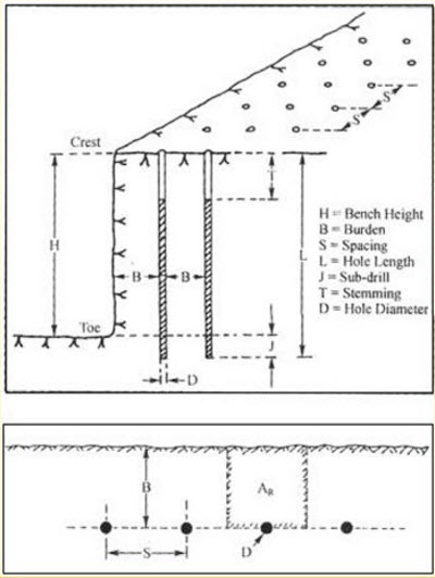
First, please take a look at each of these parameters, as labeled, and make sure that you understand what’s going on. There are two terms on the diagram that we have not yet defined. They are toe and crest. The toe is the bottom edge of the bench adjacent to the vertical wall. The crest is the top edge of the vertical or nearly vertical wall. This wall is often called the highwall.
The equations for determining the burden, spacing, and stemming require that we know the blast hole diameter. So, looking at the diameter of the hole is a good first step. This diameter is defined by the diameter of the drill bit.
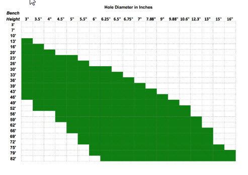
For benching, hole diameters typically range from a low of 3” to a high of 15”. If we’re benching in an underground mine, we’ll have hole diameters near the low end of that range, and for surface applications, we’ll be in the middle to upper end of that range. Just as a comparison, I would mention that for drifting, the holes are likely to be as small as 1-3/4” and probably no bigger than 3-4”. In many cases, you will have historical practice or the practices at similar mines to narrow your choices. Other times, you will already own equipment capable of drilling a limited range of sizes, and your design will be bounded accordingly.
Here’s an interesting chart, which is a compilation of the hole diameter and bench height at more than a hundred mine sites. As you can see, there is a rough relationship between the bench height and the diameter of drill used to create the blast hole for that bench.
Given a hole diameter, D, we can calculate the burden, B, the spacing, S, and the stemming, T. We will use Ash's to calculate these parameters. Note, as indicated earlier, and as will become more apparent with the discussion of the “K” factors, these relationships provide guidance not absolute precision.
Let’s talk about these “K” factors.
KB = 20 for underground application and 25 for surface, assuming a standard ANFO and a rock density of approximately 2.5 g/cm3. If the rock density is significantly greater or less than 2.5, then the factor should be examined. Here’s a table of typical rock densities for commonly mined minerals. As you can see for most of them, the suggested KB of 30 to 25 will be fine. The notable exceptions would include coal and peridotite. If you need to convert these to lb/ft3, multiply by 62.3.
| Mineral | Rock Density |
|---|---|
| Andesite | 2.5-2.8 |
| Basalt | 2.8-3.0 |
| Coal | 1.1-1.4 |
| Diabase | 2.6-3.0 |
| Diorite | 2.8-3.0 |
| Dolomite | 2.8-2.9 |
| Gabbro | 2.7-3.3 |
| Gneiss | 2.6-2.9 |
| Granite | 2.6-2.7 |
| Gypsum | 2.3-2.8 |
| Limestone | 2.3-2.7 |
| Marble | 2.4-2.7 |
| Mica schist | 2.5-2.9 |
| Peridotite | 3.1-3.4 |
| Quartzite | 2.6-2.8 |
| Rhyolite | 2.4-2.6 |
| Rock salt | 2.5-2.6 |
| Sandstone | 2.2-2.8 |
| Shale | 2.4-2.8 |
| Slate | 2.7-2.8 |
If you are using an explosive, x, with a different bulk strength, the factor KB changes as follows:
KBx = KB * (BSx)1/2, and BSx is the bulk strength of explosive X.
The other two factors are constants: KS = 1 to 1.3; and KT =0.7.
And, that’s all there is to it! More or less… this gives us a reasonable first approximation to laying out the pattern, or at least the burden and spacing along with the stemming. There are additional considerations, as well as sources of additional guidance.
An important metric is powder factor, because it tells us something about how efficient our blast is, and if we know typical powder factors from other similar mines, we can use that number to back calculate some of our design parameters. Powder factor is defined as the weight of the explosive used divided by either the volume or weight of fragmented rock. Its units are lb/ton or lb/yd3, or in the metric system, kg/tonne or kg/m3.
The calculation of the powder factor is straightforward. In practice, you will know how many pounds of explosive were used and you will know how many truck loads of rock were fragmented; and frankly, it is a good idea to keep close tabs on this in your operation. In the design stage, you can directly calculate the powder factor.
The explosive charge per unit length of hole, Mc, is: , where D is the hole diameter and is the density of the explosive. The weight of the explosive in the hole is therefore the product of the charge per unit length and the charged length of the hole, Lc. Remember that the entire hole is not filled with explosive. For example, the top 1/3 or so may be stemming; and in this case, the charged length would be 2/3 of the hole length.
The volume of fragmented rock is taken to be the product of the blast area, Ab, around the hole times the length of the hole. It is defined by a rectangle with the hole in the center. The two sides of the rectangle are and . Or simply, the area of the rectangle, Ab, is the product of the burden, B, and spacing, S. The volume of broken rock is then the area, Ab, times the length of the hole. If we want the weight of the blasted material, we need to multiply this volume by the density of the rock that will be broken by the blast.
The powder factor, PF, is:
All right, we can calculate powder factor, and we understand why it is a useful metric to compute and monitor at our operation. Earlier, I mentioned that knowing factors at similar operations could be useful to us in the design stage. How so?
If we have a known powder factor to start with, we can use that to determine a reasonable burden or spacing, which could be a good “check” on our first round of calculations. We can calculate MC directly based on the explosive that we are going to use and the hole diameter. As a starting point, we can assume that Lc will be 70% of L. We know our bench height, so we know L. The remaining unknowns are B and S. Substituting, we have:
and simplifying,
, and rearranging,
You know MC and PF, but not B or S. However, you can compute the product of B&S; and then, you can choose one, and solve for the other. At this point, you may be thinking: but wait a minute! How is this helping me, because I still have to choose B or S. True, but you are not doing so blindly. You could use B that you calculated earlier with Ash’s formula, plug that number into this equation, and voilà, you now have values for B and S. Or better yet, rather than using the B that you calculated, you might refer to a handbook where you can find burden-to-spacing ratios for many different scenarios. For example, such a table may list a typical S:B ratio of 1.25 for the type of mine of interest to you. Thus, for this ratio:
Substituting this into the equation,
, and simplifying, we have: .
Solving:
And so, using “real-world" data for powder factor and burden-to-spacing ratio, we are able to estimate a reasonable starting point in our design. Please remember that the constant, 0.56, in this equation is only valid for this example.
Here are a couple of other things to keep in mind. The degree of fragmentation will depend on the interrelationship among powder factor, burden, and spacing. We could, as an extreme case, choose to drill one hole of say 48” in diameter and pack in with explosives. The number might look good in terms of the powder factor, but what is likely to be the outcome?
This is why it’s useful to calculate these parameters in different ways, using not only Ash’s formulas but also using the fundamental definition of powder factor and available handbook data.
Clearly, it's a bit of an art, and you will go through iterations before “perfecting” your design. Nonetheless, there is a solid scientific approach to get you reasonably close.
6.3.2: Drift Round Blast Design
6.3.2: Drift Round Blast Design
For drift rounds, we are talking about driving openings, i.e., drilling, blasting, loading, and hauling, in an underground mine. These openings are horizontal or nearly so in many cases, but can be on fairly steep grades in others. Think of advancing a tunnel through a mountain – we are driving an opening through the mountain, and depending on our needs, the tunnel may be inclined or nearly horizontal.
Although the calculations that we just covered are generally applicable, designing a blasting round for drifting is more difficult. There are two reasons for this. Primarily, it is because we only have one free face. In bench blasting, we almost always have at least two. Recall, what is happening in a bench blast. As we initiate the round, the blasted and expanding material closest to the highwall is able to move freely upward and outward in the direction of the highwall. When rock is blasted, it expands by 30% or more, so it needs somewhere to expand. Furthermore, the expanding gases from the detonation of the explosive are rapidly propelling this blasted rock. After the first row of holes has been fired and the fragmented material is moving out of the way, the next row is fired, and the round evolves in an orderly sequence based on the timing delays used in the pattern. If we don’t give the blasted material the space to expand and move, we’ll have a big problem. The fragmentation will be adversely impacted, of course, but the bigger problem is that the fragmented material will tend to stay in place, and then it will be very difficult to dig or load. This is the challenge we face in drifting, because we have only one free face.
We overcome this limitation by creating a second free face; and we do this by putting cut holes in the center of the opening that we are driving. We’ll look at these cut holes in the next lesson, but, essentially, they are unloaded holes drilled in the center of the center of the opening; and then, when this new free face is created, we set off the remainder of the holes. The blasted rock from those holes is then free to expand inward towards this new free face that we created in the center of the opening, and then outward.
We can use the same formulas for drift rounds as we did for designing a blast round for a bench. However, the patterns will be significantly different. And that’s what we really need to look at next – the patterns, i.e., hole placement and timing delays that are used in bench and drift blasting. We’ll do that in the next lesson.
Before moving on to that topic, let me finish one last detail here. I said that drift blasting was more challenging for two reasons, and we just talked about the primary reason for this. The other reason is overbreak, which is fragmentation that occurs beyond the intended space. Suppose you were blasting a tunnel with a rectangular cross-section of 30’ wide by 20’ high. Your goal will be to limit fractures in the rock to the 30’x20’ opening. It’s unlikely that you could maintain a perfect opening, but limiting the fracturing beyond those boundaries to less than several inches is doable. We aren’t as particular about this in many surface applications as we are in underground mines. Why? We touched on this earlier.
These fractures are likely to become future ground control problems, costing us time and money. The fractures or cracks are likely to destabilize over time, and if there is ground water seepage, the process will accelerate. Accordingly, we have to design a round to minimize overbreak. Unfortunately, few engineers do this for lack-of-knowledge; but it is not that difficult, and we will learn how to do it in the next lesson.