Lesson 6.4: Blasting Patterns
Lesson 6.4: Blasting Patterns
We have learned much about explosives, as well as some analytical procedures to help us design blast rounds in surface and underground mines. We know that a blast round consists of multiple holes arranged in certain geometric patterns, and we know that the holes are not necessarily fired at the same time. We don’t know much about these geometric patterns for the holes, nor the time delays that may be used. You will recall from the first lesson of this Module, we watched the video clip, “Dance of the Detonators,” and we saw vivid evidence of different patterns and the use of timed shots. In this lesson, we’ll look at some common patterns, talk about their use, and we’ll look at delayed firing of holes, including the various technologies available to use for this purpose.
6.4.1: Patterns for Drift Rounds
6.4.1: Patterns for Drift Rounds
The overall pattern will be based on the desired shape of the blasted opening. If we are driving headings that will be used by people and equipment to access the ore and conduct the mining operation, we will strive to create openings that will be stable over time, and be of dimensions that meet certain requirements. These requirements may be openings of a minimum height and width to allow equipment access, or the dimensions may be based on production requirements. And there could be other considerations. Rectangular openings have sharp corners that tend to concentrate stresses, whereas elliptical or circular openings do a better job distributing the stress around the opening, and as such, they are more stable. The strength of the rock and the expected life of a particular opening will influence the shape as well as the dimensions of the opening.
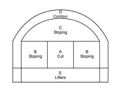
The cross-section shown here is typical, but regardless, the content that we are going to cover applies to other shapes as well. Notice that the cross-section is divided into named regions. This can be applied to cross-sections of almost any size and shape.
The purpose of the Cut is to create a second free face, which we introduced in the last section of this lesson. There are two general types of cuts: parallel cuts and angled cuts.
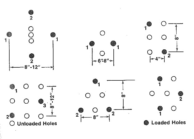
The most common type of parallel cut is known as the burn cut. Burn is the shortened name for the Viburnum Cut; so-named because it was developed for use in the lead-zinc mines found in the Viburnum trend in Missouri, back in the 1950s. Its use quickly spread to many underground mines. The burn cut consists of parallel holes, sometimes of different diameters, and always some of the holes are unloaded. The unloaded holes within the burn are referred to as relief holes. Sometimes, a few angled holes are placed within the burn, but this shouldn’t be confused with the other major type of cut, i.e., the angled cut.
Here are examples of burn cuts. The loaded holes are shaded black. The numbers adjacent to the hole refer to the firing sequence. The spacing between the holes is shown for most of them, although the diameter is not. The diameter of the holes would be the same as used for the other regions of the pattern, with the possible exception that the unloaded holes are occasionally of larger diameter. For example, if the loaded holes are around 2”, the unloaded holes of the burn cut may be 4”.
The unloaded holes provide an initial, although quite small, free face. The holes labeled “1” are fired first. The expanding rock moves toward the center and also out in front of the free face. The result is an expanded second free face, and the holes labeled “2” are then fired. They have the benefit of the larger free face, and after they have done their job, there is a sufficiently large free face in the center for the other holes to be fired.
Here is an example of the most widely used angled cut, which is known as the V-Cut. All of the holes are loaded with explosive, which is a contrast to the burn cut. The V-Cut shown here includes a baby V, which is also fairly common. The number adjacent to the holes designate the millisecond (ms) delay for the firing of that hole.
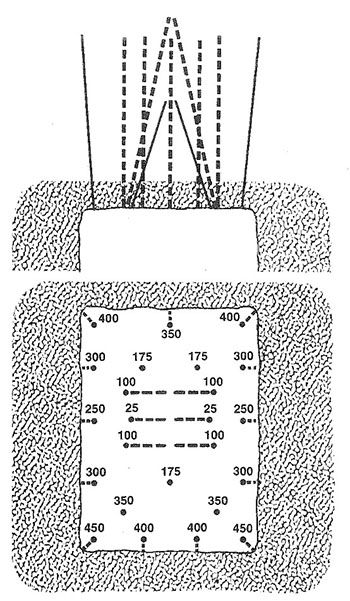
In this example of the V-cut, the baby V fires first, and creates a small free face for the firing of the two large Vs. Then, after the two large Vs have fired, there will be a sufficiently large free face to fire the remainder of the holes. Other variations of angled cuts include pyramidal and diamond-shaped arrangements.
A particular cut will tend to give better and more consistent results in a given deposit. Most underground limestone mines, for example, will settle on a V-cut after trying the burn and V-cuts, whereas in the lead mines in Missouri, there is a decided preference for the burn cut. One of the more important deciding factors will be the pull that can be achieved with the round. Pull refers to how far back into the face you can successfully blast. If we drill a hole, say 12’ back into the face, can we get good fragmentation at the back end of the hole? As you attempt to drill further and further back into the face, it becomes increasingly difficult to achieve good fragmentation near the back of the hole. The distance that you can achieve good fragmentation is known as the pull. It’s important to monitor the pull closely because if a problem has crept into your workflow, whether it is a change in the geology, an inexperienced driller or blaster, or other problem, it will often show up first as a reduced pull.
The stoping holes do most of the work of advancing the face, as they blast the most rock. These holes will begin to fire as soon as the cut holes have cleared, and they will fire in a sequence such that the holes closest to the cut will fire first, and then those further away will fire in sequence. The idea behind the sequencing of the stoping holes is to ensure a good free face for the blasted material to move through.
Lifters are not always used, but their purpose is to help ensure good fragmentation at the bottom of the drift, as this will allow for an even surface that will facilitate movement of people and equipment through the drift. Lifters can also help to throw the blasted material out into the drift to improve the ease of loading.
The holes in the Contour region are designed to ensure a smooth surface and to minimize overbreak. The contour region is properly defined by two rows of holes. The inner row is known as the buffer row, and the outer row at the perimeter of the opening is known as the contour row. Research completed in recent years provides design guidance on how to minimize overbreak using the buffer and contour rows. However, this has yet to be widely adopted.
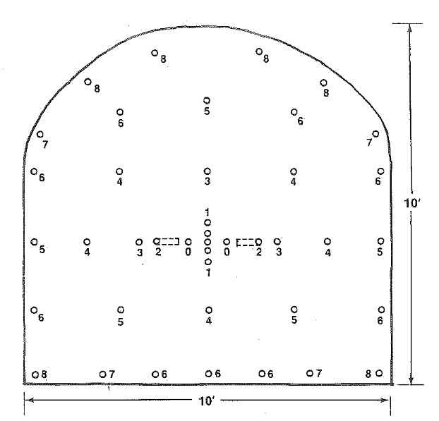
The delay sequence for a drift heading using a burn cut is shown below. Note that the burn has two angled holes; and also note that the contour region only has one row of holes around the perimeter, reflecting the longstanding practice.
The process of minimizing overbreak is referred to as controlled blasting and is documented in the following publication: NIOSH Report of Investigations 9691, A New Perimeter Control Blast Design Concept For Underground Metal/Nonmetal Drifting Applications [1], Stephen R. Iverson, William A. Hustrulid, and Jeffrey C. Johnson.
We are not going to go through the details of the design in class, but I want you to understand conceptually the process. You have the publication that you can use in the future to design a controlled blast.
This approach requires that significantly more holes be drilled and loaded than in the traditional approach. However, it is rarely about first costs only! You have to look at costs over time, and then make an informed decision. While the first costs of this approach are higher, the improved ground control should yield larger savings over time by eliminating the extensive damage zone into the back and walls.
This approach allows a burden to be calculated between the buffer row and contour row, such that the damage radius from the buffer row does not extend beyond the contour row.
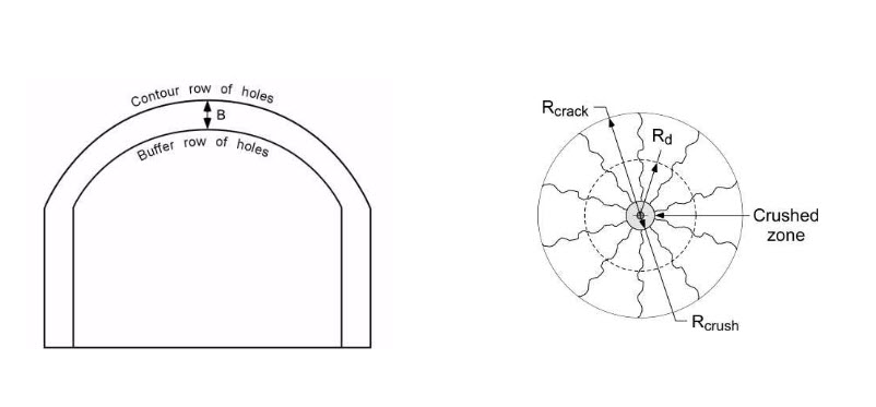
The spacing of the buffer and contour holes is based on the damage radius, Rd, as shown here.
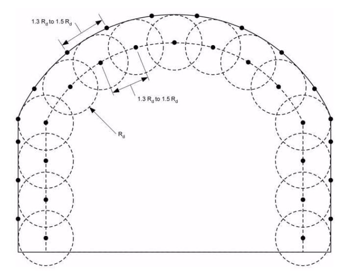
After the buffer and contour holes have been located, the lifters are added. Next, the cut holes are placed, and then, finally, the stoping holes are located. Design guidance for these holes is given in the report.
It is important to note that the contour holes are very lightly loaded. The function of these holes is to trim the wall at that point, not to create additional crushing and fracturing. This is known as decoupling of those holes. There are various ways to load these holes to achieve the desired effect. One way is to use a detonating cord in the hole instead of a blasting agent such as an emulsion or ANFO. Another is to use trim cartridges, i.e., products specifically developed for this purpose.
I think I’ll close this discussion on blast rounds for drifting by showing you a short video clip. The blast will be repeated several times. You’ll want to try to determine the type of pattern that is being used, based on your observation of the detonating cord.
6.4.2: Patterns for Bench Blasting
6.4.2: Patterns for Bench Blasting
There is a seemingly endless variety of patterns, and to make sense of it all, it’s helpful to remember that when all is said and done, the design goal is to achieve uniform fragmentation within a certain size range, and to do this it is necessary to ensure an adequate free face. Most of the variation that you will see in the patterns, and especially for surface mining, will be as result of the way in which the free faces are created and managed. The patterns for an underground bench blast tend to be straightforward – the amount of explosive that will be set off will be far more limited than in almost all surface mine blasts. As you attempt to blast larger and larger volumes, you need more holes, more rows, and the timing delays become more involved.
Here is a common surface mine layout with one free face. The numbers underneath the hole correspond to the delay sequence, first, second, third, and so forth. The numbers over the holes represent the millisecond delay for that hole.
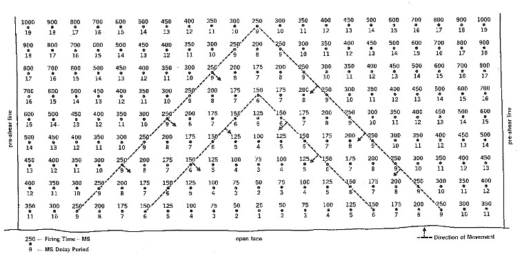
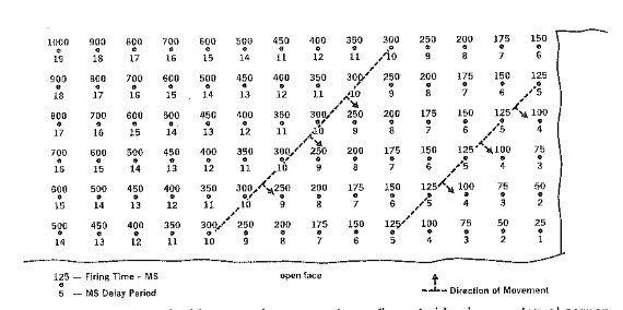
If there are two free faces, as in this case, a pattern like this is common.
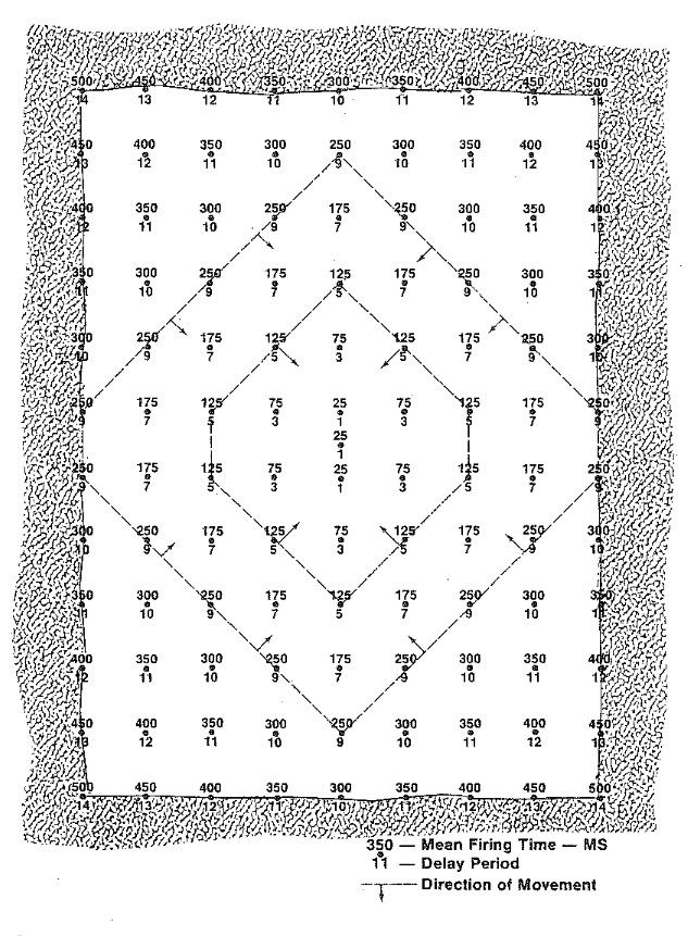
Occasionally, it is necessary to design a surface blast where there is no free face. Imagine an open field, and you are going to make the first blast so that material can be removed to initiate the surface mining cycle. By the way, the name given to this is box cut. Box cuts are a common means of accessing an orebody for underground mining, when the deposit is within a few hundred feet of the surface; and they are required as one of the initial development steps in most surface mining operations. A blasting pattern for a box cut is shown here.
These patterns can and will be modified ad nauseam to account for local geological anomalies, nearby structures such as pipelines or buildings and so on. With the few figures that we’ve examined here, you really do have comprehensive starting point for the design of your own pattern. You know how to: determine the burden, spacing, and stemming; choose an explosive or blasting agent; and lay out a pattern. One glaring gap in your knowledge base is how to achieve the desired timing delays. And so, we need to talk more about initiating the blast and the technology options available to us. We’ll do that in the next lesson.