Lesson 7.4: Aqueous Extraction Methods
Lesson 7.4: Aqueous Extraction Methods
We’ve examined surface mining from a very general perspective, and we’ve studied the class of mechanical surface mining methods. The other major class of surface mining methods is aqueous extraction. Aqueous extraction is distinguished from mechanical extraction by one characteristic: all of the aqueous methods depend on the use of water or another liquid to extract the ore, and often the water is used to aid in the gravity separation of the valuable mineral. We’ll look at three methods within this class of mining methods: Dredging, Hydraulic mining, and solution mining. These methods are important to the recovery of certain commodities, but their overall application is limited compared to mechanical extraction methods. Here in this lesson, we’ll simply introduce the basic concepts, and leave further study to advanced courses on surface mining.
7.4.1: Dredging or Dredge Mining
7.4.1: Dredging or Dredge Mining
A dredge is the principal piece of equipment used in the dredging method and, essentially, a dredge is a boat containing specialized mining and materials handling components. Accordingly, a dredge requires a body of water in which to operate. In many cases, this is a natural body of water such as a river or a lake, but in others, it is a manmade pond or small lake. Of course, the only reason for floating a dredge is to recover something of value at the bottom of this body of water. We need to add one more condition, and that is: the material of value on the bottom must be unconsolidated, such as sand and gravel, or it must be very soft. Simplistically, the dredge is designed to lift these materials of interest from the bottom up into the dredge. Shortly, we will look at how the payload is moved in a little more detail, but for now, let’s talk for a moment about the kinds of materials that are typically recovered with this method, dredging or dredge mining.
The bottom of rivers, lakes, and harbors is often a good source of gravel. Gravel can be used sometimes in concrete as well as for a variety of other purposes such as architectural and landscaping purposes. Dredging to remove this material has the additional benefit of deepening the channel or harbor, and sometimes that is the primary purpose of dredging, and the recovery of minerals is a secondary benefit… the “icing on the cake,” so to speak!
Glaciers once covered a significant portion of the Earth’s surface, and the movement of these glaciers created extensive unconsolidated deposits of materials containing not only sand and gravel, but gold, tin, diamonds, and other heavy minerals. These alluvial deposits created by glaciation, are also known as placers. I mention this here because you will sometimes hear or read about placer mining or alluvial mining. Although these terms may be used interchangeably with dredging or dredge mining, you can’t assume that to be true in all cases. As we will see, hydraulic mining may be used in these deposits as well. Regardless, if we have a body of water covering a placer deposit, we will consider strongly using dredge to recover the minerals of interest.
Moreover, if we have such a deposit that is not underwater, but is in an area that could be easily flooded, we will consider making our own lake and then using a dredge to recover the bottom materials. If the deposit is in an area with a very shallow water table, we may simply have to remove several feet of overburden, e.g., vegetation and soil, and the excavated area will fill with water on its own. Then, we can float the dredge and mine the deposit. There are other circumstances where we could create a manmade lake to mine the deposit, but it a complicated process, because we cannot take any action that could have an adverse environmental impact.
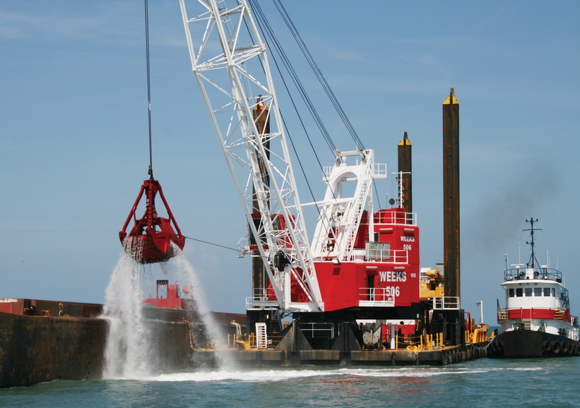
Let’s talk a bit more about the dredge itself. A dredge is defined by the way in which it recovers the ore from the bottom. The four types are bucket-wheel, ladder, clamshell, and suction. The choice will depend on the depth of the deposit below the surface of the water and the degree of consolidation of the deposit. The size of the dredge will depend on the desired production rate and the characteristics of the body of water, e.g., depth and extent. Let’s start by looking at a picture of a dredge.
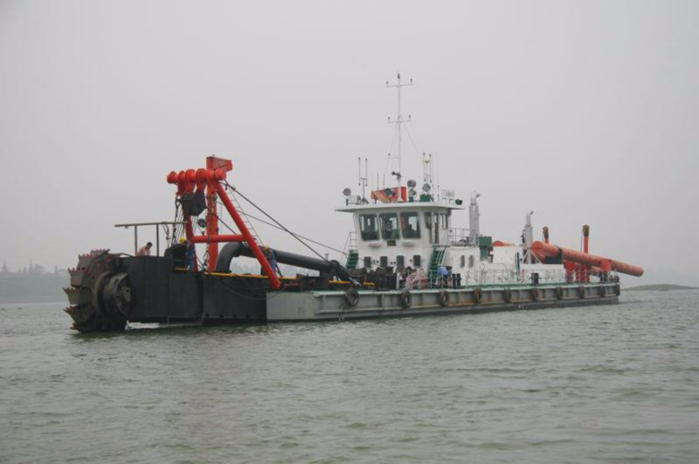
This is a large dredge, and specifically, it is a bucket-wheel dredge. You can see the bucket wheel on the left side of the picture. The bucket wheel rotates, digging into the soft material at the bottom. The dug or “mined’ material is then transfer onto the dredge. Typically, some sort of a gravity separation is employed to segregate the material of interest from the silt, mud, and other detritus of no interest. The latter is then immediately returned to the water.
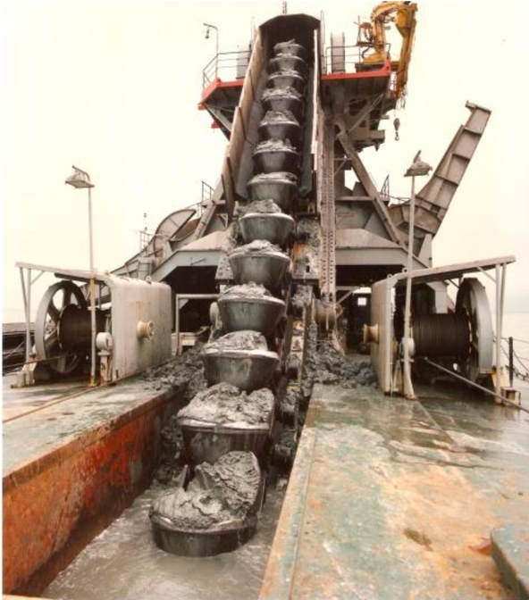
The bucket-ladder dredge is probably the most common type of dredge, as it is the most flexible method for dredging under varying conditions. The excavation equipment consists of an endless chain of open buckets that travel around a truss or “ladder.” The lower end of the ladder rests on the mine face—that is, the bottom of the water where excavation takes place—and the top end is located near the center of the dredge. The chain of buckets passes around the upper end of the ladder at a drive sprocket and loops downward to an idler sprocket at the bottom. The filled buckets, supported by rollers, are pulled up the ladder and dump their load into a hopper that feeds the separation plant on the dredge. After the valuable material has been removed, the waste is dumped off the back end of the dredge. Here is a picture of a bucket-ladder dredge, which gives a clear front view of the bucket ladder.
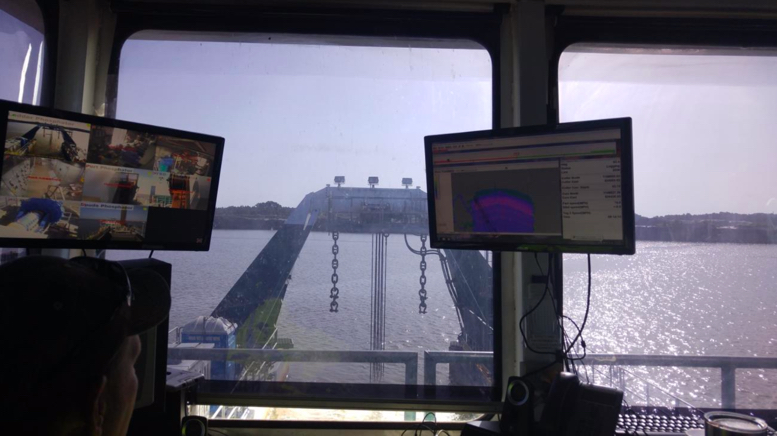
Here is a view of a bucket-ladder dredge used to mine phosphate.
And here is that same dredge in a photo taken from a distance.
Finally, here a view from the operator's cab of that dredge. Notice the computer displays providing not only video images of different parts of the dredge but also sensor data that the operator can use to better control the operation of the dredge.
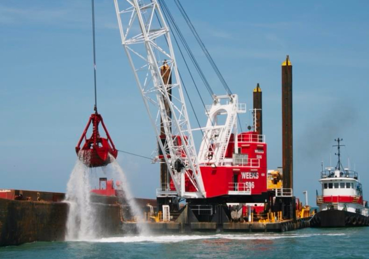
The clamshell dredge, unlike the previous two, employs a batch rather than continuous process. This type of dredge utilizes a clamshell bucket that is dropped to the bottom, scoops a bucket of material, and is hoisted back to the dredge where the bucket is dumped. This dredge can operate in deeper water than other systems and handles large material, e.g., larger rocks, well. A typical cycle time would be on the order of one minute, depending on the depth of the water. You understand the drawback of batch or discontinuous systems, and consequently, this style of dredge would only be used when its unique strengths are necessary. A typical clamshell dredge is shown here. Note the ability of this style dredge to place its payload on the dredge or on a nearby barge or structure.
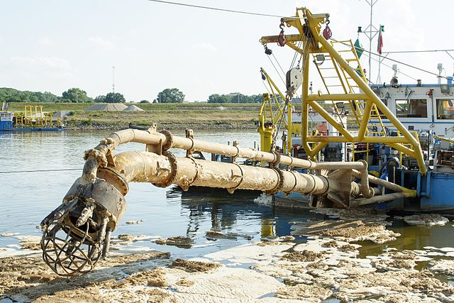
The fourth type of dredge is a hydraulic dredge. Imagine a big vacuum cleaner with a long hose – the hose is dropped to the bottom, the “vacuum” is turned on, and the material is literally sucked up the hose and captured on the dredge. Basic physics limits the amount of “lift” that can be achieved. However, the amount of lift can be supplemented with a high-pressure spray around the suction nozzle – essentially a push-pull system. This is known as hydrojet assistance. This style of dredge is suited to digging relatively small-sized and loose material such as sand and gravel, marine shell deposits, mill tailings, and unconsolidated overburden. Hydraulic dredging has also been applied to the mining of deposits containing diamonds, tin, tungsten, niobium-tantalum, titanium, and monazite. This figure diagrammatically illustrates the use of a suction dredge. Note that the use of a hydraulic pipeline to move material off the dredge is often associated with the use of this type of dredge.
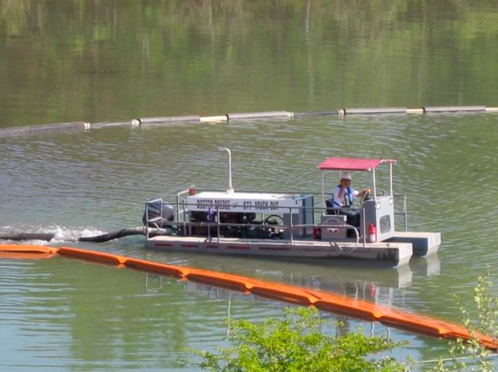
This picture shows a very small suction dredge, which might be used to clear a tailings pond, for example.
7.4.2: Hydraulicking or Hydraulic Mining
7.4.2: Hydraulicking or Hydraulic Mining
Hydraulic mining uses high-pressure water cannons, known as monitors, to dislodge relatively unconsolidated material. One of the earliest applications of hydraulic mining was to break down banks of alluvium containing gold and silver. These alluvial deposits are firm, but break down quickly upon the application of the water cannons. Of course, if digging the banks of alluvium were the goal, we could use wheeled front loaders or other traditional digging and loading equipment. The goal is not only to excavate the banks but to separate the gold, silver, or other metals from the sediments in these alluvial deposits. Toward that end, we use a gravity separation with water in a device known as a sluice. The sluice which is usually constructed, consists of a trough on a slight incline. The trough bottom may have embedded ridges. The idea is that the material laden water will flow gently down the sluice and denser materials will settle to the bottom. Toward this end, the material loosened by the water cannon is channeled to the sluice; and as it passes through the sluice, the heavier materials, e.g., grains of gold and silver, settle on the bottom of the sluice while the water and sediment are carried away.
Another important, but limited, application of hydraulicking is to break down mineral ores prior to slurry transport. Slurry transport is an important materials handling method in which a water-solid mixture is pumped over some distance. In some cases, the slurry may be pumped for 20 or 30 miles, while in others, it may be hundreds of feet. One such application is in phosphate mining. The overburden is removed, typically with a dragline, and then a monitor is used to break down the phosphate matrix into a slurry, which is then pumped to the mineral processing plant. We’re going to examine a case study in the next Lesson, and at that mine, they use a dragline to excavate the phosphate matrix and place it into a small pit where it is broken down and fed into the slurry pipeline. You’ll see some good pictures of hydraulic monitors in that case study.
7.4.3: Solution Mining
7.4.3: Solution Mining
Solution mining is the extraction of the ore through a dissolution process, i.e., we pump a solvent through the ore, the solvent dissolves the constituent of interest, and then we recover and process the resulting liquid, which is known as the solute or pregnant liquor. We can apply this method to in-situ deposits using a borehole mining method, or to mined material using a heap leaching method. In-situ, which implies “in-place” “in-the-seam”, and using an in-situ method, means that we extract, i.e., dissolve, the material of interest within the deposit and leave behind the gangue or waste minerals. In-situ recovery has the advantage of not disturbing the surface with a mining activity and of eliminating surface piles of processing plant tailings or waste. It has the disadvantage in some applications of creating a potentially hazardous environmental situation if the solvent or solute can migrate into the environment. Let’s talk about the in-situ methods first.
7.4.4: Borehole Mining Method
7.4.4: Borehole Mining Method
One hole is drilled into the deposit for the purpose of pumping the solvent into the deposit, and one is drilled at some distance from the other to recover the solute. The solvent flows between the two holes creating a cavern where the ore was dissolved. For some minerals such as common salt (NaCl) or trona, water is the solvent. For other minerals, a chemical solvent is required. Interestingly, sometimes these caverns are of greater value than the extracted mineral! In the Louisiana salt domes, for example, the caverns are used to store crude oil and natural gas. Often, multiple holes are drilled within the area of interest. Occasionally, only one hole is drilled, but the borehole is divided into an inner and outer annulus so that the solvent is forced down one, and the solute is retrieved through the other. This is the case for the Frasch process for recovering sulfur. The Frasch sulfur process uses steam to melt and dissolve the sulfur in the water, which is then forced back up the borehole; or, in other cases, the melted sulfur is allow to drain and collected in subterranean pools where it is then pumped to the surface.
7.4.5: Heap Leaching Method
7.4.5: Heap Leaching Method
Heap leaching was first used to extract very low grades of metal ore from piles of plant tailings or waste rock. In the case of copper, for example, a solution of sulfuric acid was released at the top of the pile and allowed to percolate down through the pile. The effluent was collected and washed over scrap tin. The copper would precipitate out on the tin, the tin would then be smelted, and the copper would be separated from the tin. All-in-all, it was a fairly clever and economic process to extract metal from material that otherwise would have been discarded as waste. Unfortunately, there was no thought given to the consequences of the effluent seeping into the ground, and in the end, this practice resulted in massive pollution around the mine site. The old Anaconda Copper Company mine in Butte, Montana, for example became an EPA Superfund Site! Today, heap leaching is practiced, but with proper engineering controls in place to ensure that it proceeds with no damage to the environment. Among other precautions, extensive containment barriers are constructed with multiple levels of redundancy.
Today low-grade ores are “mined” on the surface and placed on these containment pads so that the valuable metal can be leached out of these “heaps.” This is an important method for recovering gold from low-grade ore that could not be economically processed by any other means. The mining of the low-grade ore is usually by large dozers, front loaders, and trucks. Usually, the depth of the excavation is quite limited, and two of the reasons for this are that as the deposit depth increases, the grade may improve to allow economic exploitation by another mining method; and the cost of excavating this low-grade ore increases with the depth, and quickly it becomes uneconomic. The time required for the leaching to be completed can vary from weeks to years, with the latter being more common; and during this period, bacterial action, as from metal oxidizing bacteria for example, is critical to the success of the process. A variation of heap leaching involves constructing the “heap” in a dump, and calling it dump leaching. Large containment vessels are being used on a limited basis as well.
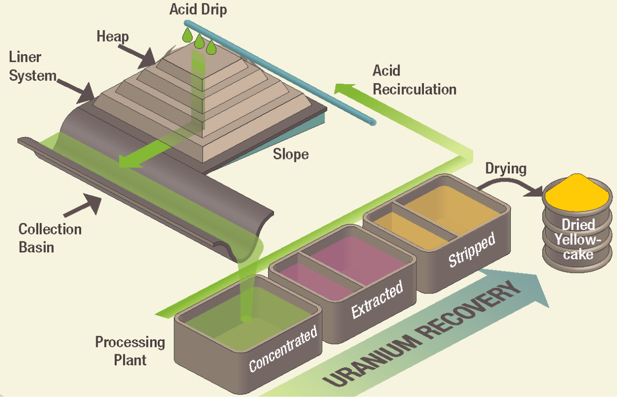
Both heap leaching and borehole mining have become the favored exploitation methods for recovering uranium. This figure illustrates a heap leaching operation.
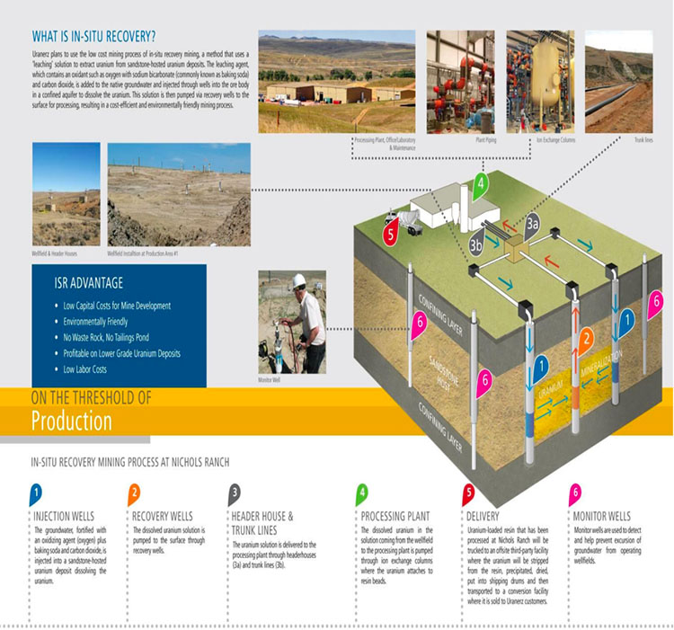
This figure illustrates the process at Uranerz’s Nichols Ranch Mine. This is a good example of how a borehole mining method is employed for in-situ recovery of a mineral.