In this lesson, you will be introduced to three types of optical sensors: airborne film mapping cameras, airborne digital mapping cameras, and satellite imaging. Each has particular characteristics, advantages, and disadvantages, but the principles of image acquisition and processing are the largely the same, regardless of the sensor type. Lesson 3 will cover photogrammetric processing of data from these sensors to produce orthophotos 1 and terrain models.
The size, or scale, of objects in a remotely sensed image varies with terrain elevation and with the tilt of the sensor with respect to the ground, as shown in Figure 2.05. Accurate measurements cannot be made from an image without rectification, the process of removing tilt and relief displacement. In order to use a rectified image as a map, it must also be georeferenced to a ground coordinate system.
If remotely sensed images are acquired such that there is overlap between them, then objects can be seen from multiple perspectives, creating a stereoscopic view, or stereomodel. A familiar application of this principle is the View-Master 2 toy many of us played with as children. The apparent shift of an object against a background due to a change in the observer's position is called parallax 3. Following the same principle as depth perception in human binocular vision, heights of objects and distances between them can be measured precisely from the degree of parallax in image space if the overlapping photos can be properly oriented with respect to each other, in other words, if the relative orientation is known (Figure 2.06).
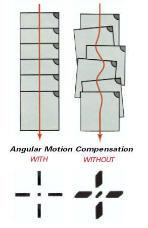
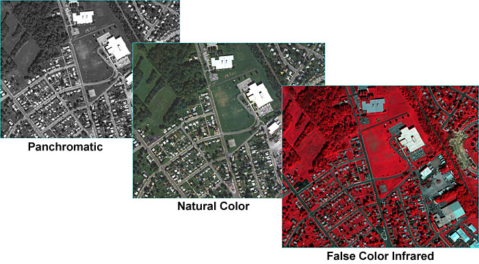
Airborne film cameras have been in use for decades. Black and white (panchromatic), natural color, and false color infrared aerial film can be chosen based on the intended use of the imagery; panchromatic provides the sharpest detail for precision mapping; natural color is the most popular for interpretation and general viewing; false color infrared is used for environmental applications. High-precision manufacturing of camera elements such as lens, body, and focal plane; rigorous camera calibration techniques; and continuous improvements in electronic controls have resulted in a mature technology capable of producing stable, geometrically well-defined, high-accuracy image products. Lens distortion can be measured precisely and modeled; image motion compensation mechanisms remove the blur caused by aircraft motion during exposure. Aerial film is developed using chemical processes and then scanned at resolutions as high as 3,000 dots per inch. In today's photogrammetric production environment, virtually all aerotriangulation, elevation, and feature extraction are performed in an all-digital work flow.
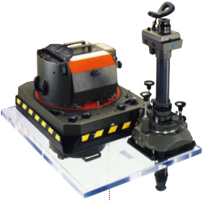
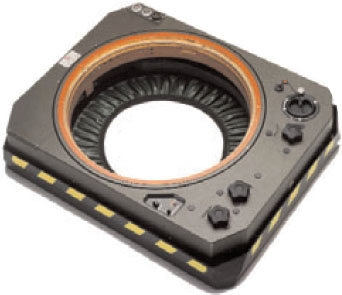
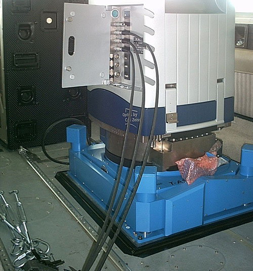
Figure 2.07 shows a Leica RC-30 aerial film camera. A hole is cut in the fuselage of the aircraft, and the camera is set in a gyro-stabilized mount as shown in Figure 2.08. This minimizes the effects of instantaneous aircraft motion and keeps the camera pointing perpendicular to the ground; the result is a sharper image and more controlled coverage from photo to photo (Figure 2.09).
In the United States, laboratory calibration of film aerial cameras is performed by the US Geological Survey, Optical Science Laboratory, in Reston, VA. If you are ever in that area, you can arrange for a visit to this unique and interesting facility; the services provided there have ensured the quality and accuracy of photogrammetrically-produced maps in the US for many decades. Most aerial survey projects require the aerial camera and lens to have been calibrated by the USGS no less than three years before the beginning of the project.
You can find a great number of USGS camera calibration certificates on the web at the Keystone Aerial Surveys Camera Calibration Center. Camera systems are calibrated as a unique combination of camera body, lens, and film magazine. If you search the Keystone database for lens number 13366, for example, you should see the following result.
Table 3.01: Example Keystone database search results.
| Cam Num | Lens Num | CFL | Report Date | Lens Type | Platen | Report |
|---|---|---|---|---|---|---|
| 5325 | 13366 | 153.287 | 5/12/2000 | 6 | 707 | 5325-051200 |
| 5325 | 13366 | 153.301 | 10/1/2003 | 6 | 5325-707 | 5325-100103 |
| 5325 | 13366 | 153.298 | 10/30/2006 | 6 | 707 | 5325-103006 |
Lens 13366 has been calibrated 3 times, always with camera number 5325. When using the Keystone database, you can click on the report link for the most recent calibration to see the complete report. The camera is a Wild RC30 4; one of the most advanced and precise aerial film mapping cameras manufactured. Pay particular attention to the sections on
- calibrated focal length
- lens distortion
- lens resolving power (AWAR)
- principal points and fiducial coordinates.
Now look at the calibration report for lens number 13081, camera number 2961, and dated 1/5/2005. This is Wild RC10 camera manufactured in the 1980s, an early predecessor to the RC30. Compare the reports, particularly the values shown for AWAR. Mapping projects executed today often specify a minimum allowable AWAR for the camera lens.
Airborne digital mapping cameras have evolved over the past few years from prototype designs to mass-produced operationally stable systems. In many aspects, they provide superior performance to film cameras, dramatically reducing production time with increased spectral and radiometric resolution. Detail in shadows can be seen and mapped more accurately. Panchromatic, red, green, blue, and infrared bands are captured simultaneously so that multiple image products can be made from a single acquisition (Figure 2.10).
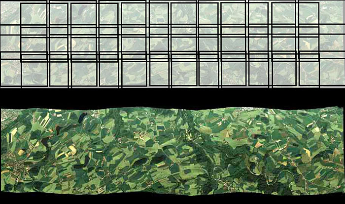
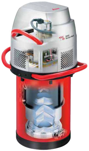
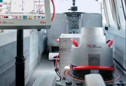
Digital camera designs are of two types: area arrays, and linear push-broom, or line-scanning, sensors. An area array camera, such as the Intergraph DMC (Figure 2.12) uses one or more two-dimensional charge-coupled device (CCD) arrays to create an image equivalent to a single frame image from an aerial film camera. The entire scene is imaged at the same moment in time, providing the same rigid geometric relationship for all points in the image with respect to each other. Coverage of an area of interest is provided with a block of overlapping photos, as shown in Figure 2.11. A push-broom sensor, such as the Leica ADS40 (Figure 2.13 and Figure 2.14), comprises multiple linear arrays, facing forward, down, and aft, which simultaneously capture along-track stereo coverage not in frame images, but in long continuous strips, or pixel carpets, made up of individual lines 1 pixel deep. Multiple linear CCD arrays capture panchromatic, near infrared, red, green, and blue bands (Figure 2.15). Pointing the CCD arrays at aft, nadir, and forward viewing angles allows the sensor to capture multiple perspectives of the same point on the ground in a single pass, creating the stereo views required to extract elevation information (Figure 2.16).
High-resolution satellite imagery is now available from a number of commercial sources, both foreign and domestic. The federal government regulates the minimum allowable GSD for commercial distribution, based largely on national security concerns; 0.6-meter GSD is currently available, with higher-resolution sensors being planned for the near future (McGlone, 2007). The image sensors are based on a linear push-broom design. Each sensor model is unique and contains proprietary design information; therefore, the sensor models are not distributed to commercial purchasers or users of the data. Through commercial contracts, these satellites provide imagery to NGA in support of geospatial intelligence activities around the globe.
Calibration of digital aerial cameras and satellite sensors is a much more complex process than calibration of a film camera. The digital sensor should be characterized for its radiometric response as well as for internal geometry. ASPRS and a number of federal government agencies have been working with sensor manufacturers to establish guidelines and procedures for sensor calibration and data product characterization. It is an ongoing effort, and standards are just beginning to emerge. The USGS Remote Sensing Technologies Project maintains a website with information on digital camera calibration efforts, as well as collaborative efforts, such as the Interagency Digital Imagery Working Group (IADIWG) and the Joint Agency Commercial Imagery Evaluation (JACIE) group.
As digital aerial photography has matured, it has become integrated into many consumer-level, web-based applications, such as Google Earth and numerous navigation and routing packages. Microsoft has recently deployed a large number of aerial survey planes equipped with the Vexcel UltraCam sensor in an ambitious Global Ortho program. Their goal is to provide very high resolution color imagery over the entire land surface of the Earth, made publicly available through the Bing Maps platform. The following video describes the data acquisition experience and process.
1 Orthophoto. (2007, November 21). In Wikipedia, The free encyclopedia. Retrieved December 4, 2007, from http://en.wikipedia.org/wiki/Orthophoto
2 View-Master (2007, November 9). In Wikipedia, The free encyclopedia. Retrieved December 5, 2007, http://en.wikipedia.org/wiki/View-master
3 Parallax. (2007, 29 November). In Wikipedia, The free encyclopedia. Retrieved December 5, 2007, http://en.wikipedia.org/wiki/Parallax
4 Wild was purchased by Leica Geosystems, which has since been incorporated into Hexagon. The camera referenced in this report is of the same type shown in Figure 7.