3.3 Gasification
Now, we will go into gasification and compare it to combustion. Gasification is a process that produces syngas, a gaseous mixture of CO, CO2, H2, and CH4, from carbonaceous materials at high temperatures (750 – 1100°C). Gasification is a partial oxidation process; the reaction takes place with a limited amount of oxygen. The overall process is endothermic (requires heat to keep the reaction going), so it requires either the simultaneous burning of part of the fuel or the delivery of an external source of heat to drive the process.
Historically, gasification was used in the early 1800s to produce lighting, in London, England (1807) and Baltimore, Maryland (1816). It was manufactured from the gasification of coal. Gasification of coal, combined with Fischer-Tropsch synthesis was one method that was used during WWII to produce liquid fuel for Germany because they did not have access to oil for fuel. It has also been used to convert coal and heavy oil into hydrogen for the production of ammonia and urea-based fertilizers. As a process, it continues to be used in South Africa as a source of liquid fuels (gasification followed by Fischer-Tropsch synthesis).
Gasification typically takes place at temperatures from 750-1100°C. It will break apart biomass (or any carbon material), and usually, an oxidizing agent is added in insufficient quantities. The products are typically gas under these conditions, and the product slate will vary depending on the oxidizing agent. The products are typically hydrogen, carbon monoxide, carbon dioxide, and methane. There may also be some liquid products depending on the conditions used. Gasification and combustion have some similarities; the figure below shows the variation in products between gasification and combustion. The table shows a comparison of the conditions.
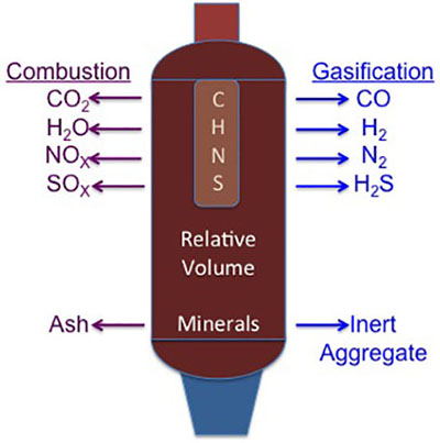
| Specification | Combustion | Gasification |
|---|---|---|
| Oxygen Use | Uses excess | Uses limited amounts |
| Process Type | Exothermic | Endothermic |
| Product | Heat | Combustible Synthesis |
Zones of Gasification
There are several zones that the carbon material passes through as it proceeds through the gasifier:
- drying
- pyrolysis
- combustion
- reduction
The schematic below shows the zones and the products that typically occur during that part of the process. First, we will discuss what happens in each zone. We will also be looking at different gasifier designs to show these zones change depending on the design, and each design has advantages and disadvantages.
The drying process is essential to remove surface water, and the “product” is water. Water can be removed by filtration, evaporation, or a combination of both. Typically, waste heat is used to do the evaporation.
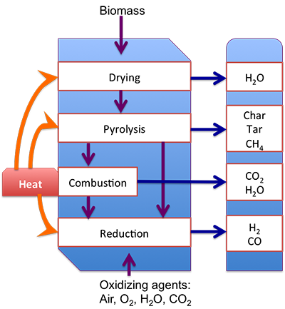
Diagram showing different regions and products in a gasifier. Heat is applied to the entire system, oxidizing agents such as air, O2, H2O, and CO2 enter from the bottom and biomass enters from the top.
The biomass first goes through drying which removes water. It then goes through pyrolysis which produces char, tar, and methane. From pyrolysis, the biomass can go to reduction or combustion which produces carbon dioxide and water. If the biomass goes through combustion it also then goes to reduction which produces hydrogen gas and carbon monoxide.
Pyrolysis is typically the next zone. If you look at it as a reaction:
where x is the mass fraction of tars in the volatiles. Volatile gases are released from the dry biomass at temperatures ranging up to about 700oC. These gases are non-condensable vapors such as CH4, CO, CO2, and H2 and condensable vapor of tar at the ambient temperature. The solid residues are char and ash. A typical method to test how well a biomass material will pyrolyze is thermogravimetric analysis; it is similar to the proximate analysis. However, the heating rate and oxidizing agent can be varied, and the instrument can be used to determine the optimum temperature of pyrolysis.
Gasification Process and Chemistry: Combustion and Reduction
A limited amount of oxidizing agent is used during gasification to partially oxidize the pyrolysis products of char (C), tar, and gas to form a gaseous mixture of syngas mainly containing CO, H2, CH4, and CO2. Common gasifying agents are air, O2, H2O, and CO2. If air or oxygen is used as a gasifying agent, partial combustion of biomass can supply heat for the endothermic reactions.
Combustion of gases:
The equivalence ratio (ER) is the ratio of O2 required for gasification, to O2 required for full combustion of biomass. The value of ER is usually 0.2 - 0.4. At too high ER values, excess air causes unnecessary combustion of biomass and dilutes the syngas. At too low ER values, the partial combustion of biomass does not provide enough oxygen and heat for gasification.
There are several reactions that can take place in the reduction zone. There are three possible types of reactions: 1) solid-gas reactions, 2) tar-gas reactions, and 3) gas-gas reactions. Essentially, H2O and CO2 are used as gasifying agents to increase the H2 and CO yields. The double-sided arrow represents that these reactions are reversible depending on the conditions used.
Solid-gas reactions include:
Tar-gas reactions include:
Gas-gas reactions include:
The reactions can be affected by reaction equilibrium and kinetics. For a long reaction time: 1) chemical equilibrium is attained, 2) products are limited to CO, CO2, H2, and CH4, and 3) low temperatures and high pressures favor the formation of CH4, whereas high temperatures and low pressures favor the formation of H2 and CO. For a short reaction time: 1) chemical equilibrium is not attained, 2) products contain light hydrocarbons as well as up to 10 wt% heavy hydrocarbons (tar), and 3) steam injection and catalysts can shift the products toward lower molecular weight compounds.
Gasifier Designs
There are several types of gasifier designs:
- updraft
- downdraft
- cross downdraft
- fluidized bed
- plasma
The first type of gasifier is the updraft design. The advantages include that it is a simple design and is not sensitive to fuel selection. However, disadvantages include a long start-up time, production of high concentrations of tar, and a general lack of suitability for modern heat and power systems.
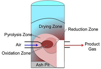
The downdraft gasifier is similar, but the air enters in the middle of the unit and gases flow down and out. The oxidation and reduction zones change places. Advantages of this design include low tar production, low power requirements, a quicker response time, and a short start-up time. However, it has a more complex design, fuel can be fouled with slag, and it cannot be scaled up beyond 400 kg/h.
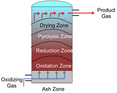
Schematic of an Updraft Gasifier. The diagram looks like a cylinder with oxidizing gas entering at the bottom and flowing up and out at the top. There are 5 layered zones in the gasifier. Starting at the bottom there is the ash zone, the oxidation zone, the reduction zone, the pyrolysis zone, and the drying zone.
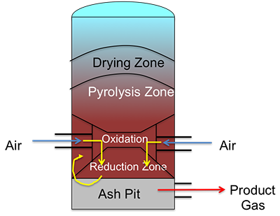
Schematic of a downdraft gasifier. The diagram again looks like a cylinder and again has 5 layered zones. From the bottom up they are the ash pit, the reduction zone, the oxidation zone, the pyrolysis zone, and the drying zone. The air enters in the middle of the gasifier at the oxidation zone and the air flows down and comes out the bottom as product gas.
The crossdraft design gasifier is similar to the downdraft, it has a quicker response time and a short start-up time; it is also complex in design, cannot use high mineral-containing fuels, and fuel can be contaminated with slag from ash.
With a fluidized bed design gasifier, the action of this gasifier is similar to how water might boil, except the air (or other gas) flows through the fines (the sample and sand) at temperature, creating a bubbling effect similar to boiling. Because of this action, it has the advantages of greater fuel flexibility, better control, and a quick response to changes. But because of these advantages, these types of gasifiers have a higher capital cost, and a higher power requirement, and must be operated on high particulate loading.
Schematic of a crossdraft gasifier. This gasifier again looks like a cylinder and has all 5 of the zones the previous 2 did. However, instead of layers, the zones look more like a bullseye. Air enters halfway up the cylinder in the very center which is the oxidation zone. Around the oxidation zone is the reduction zone and outside that is the pyrolysis zone. The drying zone is around them all. The ash pit is still a layer at the very bottom. Product gas comes out at the same level the air initially came in.
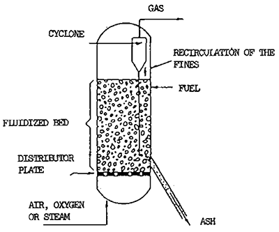
Schematic of a fluidized bed design gasifier. This gasifier looks like a cylindrical capsule where air, oxygen or steam enters from the bottom. Near the bottom, there is a distributor plate. The fluidized bed with the fuel sits on top of the plate and at the bottom of the fluidized bed, there is an exit for the ash. There is a mechanism to recirculate the fines near the top of the fluidized bed. To exit, the gas flows through a cyclone and out the top of the gasifier.
One of the new design gasifiers is a plasma gasifier design. Plasma gasification uses extremely high temperatures in an oxygen-starved environment to decompose waste material into small molecules and atoms so that the compounds formed are very simple and form syngas with H2, CO, and H2O. This type of unit functions very differently, as electricity is fed to a torch that has two electrodes – when functioning, the electrodes create an arc. Inert gas is passed through the arc, and, as this occurs, the gas heats to temperatures as high as 3,000 °C (Credit: Westinghouse Plasma Corporation). The advantages of such units include:
- process versatility
- superior emission characteristics
- no secondary treatment of byproducts
- valuable byproducts
- enhanced process control
- volume reduction of material fed
- small plant size
Units such as these are more expensive and scaling up is still in the research stage. These types of units are most commonly used for municipal waste sludge.
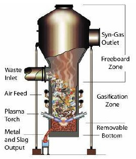
Schematic of a plasma design gasifier. This looks like a funnel with a lid. About halfway up there is a waste inlet. Below that there is an inlet for air or oxygen and near the bottom there are plasma torches. The syngas exits from an outlet at the top and slag and recovered metals are collected from an outlet at the bottom.
General information on gasification
So what products are made, what advantages are there to using various oxidizing sources, how are the byproducts removed, and how is efficiency improved? Besides syngas, other products are made depending on the design. As stated previously, the syngas is composed of H2, CO, CO2, H2O, and CH4. Depending on the design, differing amounts of tar and char can also be made. For example, for steam fluidized gasification of wood sawdust at atmospheric pressure and 775°C, 80% of the carbon will be made into syngas, 4% of the carbon will produce tar, and 16% will produce char (Herguido J, Corella J, Gonzalez-Saiz J. Ind Eng Chem Res 1992; 31: 1274-82.)
There are multiple uses for syngas, for making hydrocarbon fuels, for producing particular chemicals, and for burning as a fuel; therefore, syngas has a heating value. The heating value can be calculated by the volumetric fraction and the higher heating values (HHV) of gas components, which is shown in this equation:
where:
A problem based on this equation and HHVs will be included in the homework.
Other factors are determined for optimal gasification. Thermal efficiency is the conversion of the chemical energy of solid fuels into chemical energy and sensible heat of gaseous products. For high-temperature/high-pressure gasifiers, the efficiency is high, ~90%. For typical biomass gasifiers, the efficiency is reduced to 70-80% efficiency. Cold gas efficiency is the conversion of the chemical energy of solid fuel to the chemical energy of gaseous products; for typical biomass gasifiers, the efficiency is 50-60%.
There are several processing factors that can affect different aspects of gasification. The following table shows the main advantages and technical challenges of different gasifying agents. Steam and carbon dioxide as oxidizing agents are advantageous in making high-heating value syngas with more hydrogen and carbon monoxide than other gases but also require external heating sources and catalytic tar reformation.
| Gasifying Agent | Main Advantages | Main Technical Challenges |
|---|---|---|
| Air |
Partial combustion for heat supply of gasification. Moderate char and tar content. |
Low heating value (3-6 MJ/Nm3) Large amount of N2 in syngas (i.e., >50% by volume) Difficult determination of equivalence ratio (ER) |
| Steam |
High heating value syngas (10-15 MJ/Nm3) H2-rich syngas (i.e., >50% by volume) |
Requires indirect or external heat supply for gasification High tar content in syngas Tar requires catalytic reforming to syngas unless used to make chemicals |
| Carbon dioxide |
High heating value syngas High H2/CO and low CO2 in syngas |
Requires indirect or external heat supply Tar requires catalytic reforming to syngas unless used to make chemicals |
Basic design features can also affect the performance of a gasifier. The table below shows the effect of a fixed bed versus a fluidized bed and the differences in temperature, pressure, and equivalence ratio. Fixed/moving beds are simpler in design and favorable on a small scale economically, but fluidized bed reactors have higher productivity and low byproduct generation. The rest of the table shows how increased temperature can also favor carbon conversion and the HHV of the syngas, while increased pressure helps with producing high-pressure syngas without compression to higher pressures downstream.
| Bed Design | Main Advantages | Main Technical Challenges |
|---|---|---|
| Fixed/moving bed |
Simple and reliable design Favorable economics on a small scale |
Long residence time Non-uniform temperature distribution in gasifiers High char and/or tar contents Low cold gas efficiency Low productivity (i.e., ~5 GJ/m2h) |
| Fluidized bed |
Short residence time High productivity (i.e., 20-30 GJ/m2h) Uniform temperature distribution in gasifiers Low char and/or tar contents High cold gas efficiency Reduced ash-related problems |
High particulate dust in syngas Favorable economics on a medium to large scale |
| Increase of temperature |
Decreased tar and char content Decreased methane in syngas Increased carbon conversion Increased heating value of syngas |
Decreased energy efficiency Increased ash-related problems |
| Increase of pressure |
Low tar and char content No costly syngas compression is required for downstream utilization of syngas |
Limited design and operational experience Higher cost of gasifier at small scale |
| Increase of ER (Equivalence Ratio) | Low tar and char content | Decreased heating value of syngas |
Product Cleaning
The main thing that has to be done to clean the syngas is to remove char and tar. The char is typically in particulate form, so the particulates can be removed in a way similar to what was described in the power plant facility. Typically for gasifiers, the method of particulate filtration includes gas cyclones (removal of particulate matter larger than 5 μm). Additional filtration can be done using ceramic candle filters or moving bed granular filters.
Tars are typically heavy liquids. In some cases, the tars are removed by scrubbing the gas stream with a fine mist of water or oil; this method is inexpensive but also inefficient. Tars can also be converted to low molecular weight compounds by “cracking” into CO and H2 (these are typically the desired gases for syngas). This is done at high temperature (1000°C) or with the use of a catalyst at 600-800°C. Tars can also be “reformed” to CO and H2, which can be converted into alcohols, alkanes, and other useful products. This is done with steam and is called steam reforming of tar; the reaction conditions are at a temperature of ~250°C and pressure of 30-55 atm. The reaction is shown below and is the same reaction as that shown in reaction 11:
Tar steam reforming reaction:
Steam reforming has advantages. It is generally a safer operation since there isn’t any oxygen in the feed gases, and it produces a higher H2/CO ratio syngas product than most alternatives. The main disadvantage is a lower thermal efficiency, as heat must be added indirectly because the reaction is endothermic.
Syngas Utilization
As stated earlier, syngas has multiple uses. Syngas can be used to generate heat and power, and can even be used to turn a turbine in some engineering designs. Syngas can also be used as the synthesis gas for Fischer-Tropsch fuel production, synthesis of methanol and dimethyl ether (DME), fermentation for the production of biobased products, and production of hydrogen.
So, how is syngas utilized in heat and power generation? Syngas can be used in pulverized coal combustion systems; it help the coal to ignite and to prevent the plugging of the coal feeding system. Biomass gasification can ease ash-related problems. This is because the gasification temperature is lower than in combustion, and once gasified, can supply clean syngas to the combustor. Adding a gasifier to a combustion system helps in the utilization of a variety of biomass sources with large variations in properties. Once the syngas has been cleaned, it can be fed to gas engines, fuel cells, or gas turbines for power generation.
Syngas may also be used to produce hydrogen. When biomass is gasified, a mixture of H2, CO, CH4, and CO2 is produced. Further reaction to hydrogen can be done using water reforming and water-gas shift reactions:
Water reforming reaction for CH4 to H2:
Water-gas shift reaction for CO to H2 (as shown earlier):
Carbon dioxide may also be removed, as it is typically an undesirable component. One method to keep it from going into the atmosphere is to do chemical adsorption:
Syngas can also be utilized for the Fischer-Tropsch synthesis of hydrocarbon fuels. Variable chain-length hydrocarbons can be produced via a gas mixture of CO and H2 using the Fischer-Tropsch method. The reaction for this is:
In order for the reaction to take place, the ratio should be close to 2:1, so gases generated via gasification may have to be adjusted to fit this ratio. Inert gases also need to be reduced, such as CO2, and contaminants such as H2S, as the contaminants may lower catalyst activity.
Methanol and dimethyl ether can also be produced from syngas. The reactions are:
Dimethyl ether (DME) can be made from methanol:
Syngas can also be fermented to produce bio-based products. This will be discussed in detail in a later lesson.