
Absorption cycle is one of the promising methods to utilize the solar heat for space cooling in domestic and industrial applications. Until recently the absorption cooling technology was not readily available for small capacity applications and was quite expensive compared to the traditional vapor compression cooling technology. However, there is a significant opportunity to combine an absorption system with building envelop design to provide environmentally benign way of controlling internal environment using solar energy.
There are two basic types of absortpion cooling cycles: (1) Lithium Bromide (LiBr)-Water and (2) Ammonia-Water. The LiBr-H2O appears to be more suitable for small-scale and low-cost solar applications due to lower operating temperature of this cycle (Florides et al., 2001).
Absorption systems are in some way similar to vapor compression systems, but differ in pressurization phase. Maybe it can be useful to briefly review how the conventional vapor compression systems work, such as those found in electric refrigerators.
In a compression refrigeration cycle, a working fluid (refrigerant) is compressed via electrical energy input to a mechanical compressor. We can recall from thermodynamics' ideal gas law that pressure multiplied by volume is proportional to temperature:
PV = nRT
As such, when the working fluid undergoes compression (an increase in pressure in the same volume), the temperature of the working fluid must increase. Then, the compressed, higher temperature fluid is pumped through a heat exchanger, where it exchanges heat with the ambient air (this is either the coil and fins you see on your outdoor unit of your heat pump, the coil and fins on the back of your window air conditioner unit, or the coil and fins on the back of your electric refrigerator). This process results in a heat loss from the fluid to the surrounding air (which is cooler than the fluid), effectively cooling the fluid.
Next, this colder (but still compressed) working fluid passes through an expansion valve where it is returned to its pre-compression pressure (at the same volume) which requires that the fluid decrease in temperature according to the ideal gas law again. This step drops the temperature of the working fluid to a level that can be used for cooling of your space or refrigerator.
The process of cooling in such a refrigerator is essentially transfer of heat from the target cooled space to the working fluid and to the environment. The cycle loops here, with the fluid exiting the heat exchanger to your space/fridge and heading back to the compressor.
Now let us look how the absorption cooling cycle works.
It was already mentioned that in comparison with the conventional refrigeration cycle (described above), the absorption cycle has a different kind of pressurization. Instead of using a mechanical compressor (usually power-expensive), it completes pressurization by dissolving the refrigerant in the absorbent. In case of LiBr-H2O system, LiBr acts as an absorbent, and H2O acts as refrigerant. LiBr is a salt, so we can guess that if the LiBr-H2O solution boils, water will go, and salt will stay. The solubility limit of LiBr in water is quite high, so the solution used in the absorption cycle is very concentrated (~60% LiBr by mass).
There are four main components of the absorption cooling cycle: generator, absorber, condenser, and evaporator (where the cooling effect is achieved). The simplified schematic diagram of the absorption cycle is shown below:
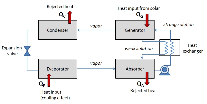
The solar (or other external) heat input to the system is denoted QG. The heat that is absorbed by the system from the cooled space due to evaporation process is denoted QE. The heat rejected from condenser and absorber are shown respectively as QC and QA. The overall energy balance of the system is therefore:
QC + QA = QG + QE
The cycle, step by step goes as follows:
- Absorber contains the absorbent-refrigerant mixture (in this case LiBr-H2O), which is delivered by a liquid pump to the generator. The solution passes through a heat exchanger where its temperature increases. We can call this pumped mixture "strong solution" because it is rich in refrigerant.
- Generator heats the absorbent-refrigerant mixture using the external heat source - for example, solar heat from a flat-plate collector. The heat causes the solution to boil, and water turns into vapor flows to the condenser. Remaining LiBr with still some water is sent back to absorber via a heat exchanger (this returning fraction can be called "weak solution" since it is depleted of refrigerant).
- Condenser condenses the water vapor coming from the generator. At this point heat is rejected, since condensation process is exothermic. This liquid condensate is now directed to the evaporator through an expansion valve.
- Evaporator absorbs the heat from the load (cooled space) due to evaporation of the refrigerant at low pressure. This creates the cooling effect. Vaporized refrigerant then flows back to the absorber, where it mixes with the "weak solution" of LiBr.
Then the cycle continues. In this scheme, the solar heat provided to the generator is driving this cycle. The cooling effect achieved in the evaporator is applied to either chilling water flow or air flow that is passed through the evaporator. This chilling water flow is not part of the cycle, it simply acts as a vehicle to deliver "cold" to the target space or environment.
The following practical values of the system parameters are typical for LiBr-H2O system:
- Generator temperature ~75oC
- Evaporator temperature ~6oC
- Heat exchanger temperature ~55oC
- "Strong" solution 55% LiBr(aq) by mass fraction
- "Weak" solution 60% LiBr(aq) by mass fraction
The performance of such system can be characterized by cooling coefficient of performance (COP metric):
COPcooling = QE/QG
which is essentially the heat load of the evaporator per unit of heat load of the generator. This metric can become useful when comparing system costs. The COP values for LiBr-H2O system is typically in the range from 0.6 to 0.8 (Duffie and Beckman, 2013).
The following reading will give you more details and analysis of the adsorption cooling systems.
Reading Assignment
Duffie, J.A., and Beckman, W.A., Solar Engineering of Thermal Processes, Wiley and Sons, 2013, Chapter 15. Sections 15.1-15.6.
The temperature-pressure diagram presented in Figure 15.2.2 is a typical way to analyze cooling and heating cycles. Try to identify different stages and points of the cycle on this diagram and understand why temperature and pressure change the way they do.
Probing question:
What are some key advantages of the absorption cooling cycle compared to the conventional compression refrigeration cycle?
- An absorption cooling cycle (including a solar driven one) can work without any mechanical pumps, providing cooling without any electrical input.
- An absorption cooling cycle is quieter and has no vibrations (from compressors/pumps).
- An absorption cooling cycle uses working fluids that are more environmentally friendly.
- A solar absorption cooling cycle, with some storage, is synchronized with solar driven heat gains providing a real-time energy source that scales with the load.