6.3.1: Bench Blasting
Here is a sketch of a bench, showing a few boreholes, and the design variables. This bench could be in an underground or surface mine. Our goal will be to calculate values for many of the parameters shown on this diagram.
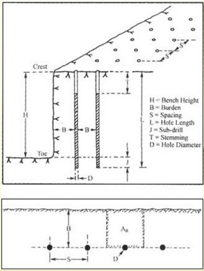
First, please take a look at each of these parameters, as labeled, and make sure that you understand what’s going on. There are two terms on the diagram that we have not yet defined. They are toe and crest. The toe is the bottom edge of the bench adjacent to the vertical wall. The crest is the top edge of the vertical or nearly vertical wall. This wall is often called the highwall.
The equations for determining the burden, spacing, and stemming require that we know the blast hole diameter. So, looking at the diameter of the hole is a good first step. This diameter is defined by the diameter of the drill bit.
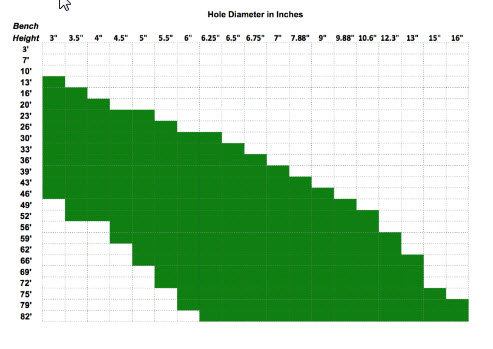
For benching, hole diameters typically range from a low of 3” to a high of 15”. If we’re benching in an underground mine, we’ll have hole diameters near the low end of that range, and for surface applications, we’ll be in the middle to upper end of that range. Just as a comparison, I would mention that for drifting, the holes are likely to be as small as 1-3/4” and probably no bigger than 3-4”. In many cases, you will have historical practice or the practices at similar mines to narrow your choices. Other times, you will already own equipment capable of drilling a limited range of sizes, and your design will be bounded accordingly.
Here’s an interesting chart, which is a compilation of the hole diameter and bench height at more than a hundred mine sites. As you can see, there is a rough relationship between the bench height and the diameter of drill used to create the blast hole for that bench.
Given a hole diameter, D, we can calculate the burden, B, the spacing, S, and the stemming, T. We will use Ash's to calculate these parameters. Note, as indicated earlier, and as will become more apparent with the discussion of the “K” factors, these relationships provide guidance not absolute precision.
Let’s talk about these “K” factors.
KB = 20 for underground application and 25 for surface, assuming a standard ANFO and a rock density of approximately 2.5 g/cm3. If the rock density is significantly greater or less than 2.5, then the factor should be examined. Here’s a table of typical rock densities for commonly mined minerals. As you can see for most of them, the suggested KB of 30 to 25 will be fine. The notable exceptions would include coal and peridotite. If you need to convert these to lb/ft3, multiply by 62.3.
| Mineral | Rock Density |
|---|---|
| Andesite | 2.5-2.8 |
| Basalt | 2.8-3.0 |
| Coal | 1.1-1.4 |
| Diabase | 2.6-3.0 |
| Diorite | 2.8-3.0 |
| Dolomite | 2.8-2.9 |
| Gabbro | 2.7-3.3 |
| Gneiss | 2.6-2.9 |
| Granite | 2.6-2.7 |
| Gypsum | 2.3-2.8 |
| Limestone | 2.3-2.7 |
| Marble | 2.4-2.7 |
| Mica schist | 2.5-2.9 |
| Peridotite | 3.1-3.4 |
| Quartzite | 2.6-2.8 |
| Rhyolite | 2.4-2.6 |
| Rock salt | 2.5-2.6 |
| Sandstone | 2.2-2.8 |
| Shale | 2.4-2.8 |
| Slate | 2.7-2.8 |
If you are using an explosive, x, with a different bulk strength, the factor KB changes as follows:
KBx = KB * (BSx)1/2, and BSx is the bulk strength of explosive X.
The other two factors are constants: KS = 1 to 1.3; and KT =0.7.
And, that’s all there is to it! More or less… this gives us a reasonable first approximation to laying out the pattern, or at least the burden and spacing along with the stemming. There are additional considerations, as well as sources of additional guidance.
An important metric is powder factor, because it tells us something about how efficient our blast is, and if we know typical powder factors from other similar mines, we can use that number to back calculate some of our design parameters. Powder factor is defined as the weight of the explosive used divided by either the volume or weight of fragmented rock. Its units are lb/ton or lb/yd3, or in the metric system, kg/tonne or kg/m3.
The calculation of the powder factor is straightforward. In practice, you will know how many pounds of explosive were used and you will know how many truck loads of rock were fragmented; and frankly, it is a good idea to keep close tabs on this in your operation. In the design stage, you can directly calculate the powder factor.
The explosive charge per unit length of hole, Mc, is: , where D is the hole diameter and is the density of the explosive. The weight of the explosive in the hole is therefore the product of the charge per unit length and the charged length of the hole, Lc. Remember that the entire hole is not filled with explosive. For example, the top 1/3 or so may be stemming; and in this case, the charged length would be 2/3 of the hole length.
The volume of fragmented rock is taken to be the product of the blast area, Ab, around the hole times the length of the hole. It is defined by a rectangle with the hole in the center. The two sides of the rectangle are and . Or simply, the area of the rectangle, Ab, is the product of the burden, B, and spacing, S. The volume of broken rock is then the area, Ab, times the length of the hole. If we want the weight of the blasted material, we need to multiply this volume by the density of the rock that will be broken by the blast.
The powder factor, PF, is:
All right, we can calculate powder factor, and we understand why it is a useful metric to compute and monitor at our operation. Earlier, I mentioned that knowing factors at similar operations could be useful to us in the design stage. How so?
If we have a known powder factor to start with, we can use that to determine a reasonable burden or spacing, which could be a good “check” on our first round of calculations. We can calculate MC directly based on the explosive that we are going to use and the hole diameter. As a starting point, we can assume that Lc will be 70% of L. We know our bench height, so we know L. The remaining unknowns are B and S. Substituting, we have:
and simplifying,
, and rearranging,
You know MC and PF, but not B or S. However, you can compute the product of B&S; and then, you can choose one, and solve for the other. At this point, you may be thinking: but wait a minute! How is this helping me, because I still have to choose B or S. True, but you are not doing so blindly. You could use B that you calculated earlier with Ash’s formula, plug that number into this equation, and voilà, you now have values for B and S. Or better yet, rather than using the B that you calculated, you might refer to a handbook where you can find burden-to-spacing ratios for many different scenarios. For example, such a table may list a typical S:B ratio of 1.25 for the type of mine of interest to you. Thus, for this ratio:
Substituting this into the equation,
, and simplifying, we have: .
Solving:
And so, using “real-world" data for powder factor and burden-to-spacing ratio, we are able to estimate a reasonable starting point in our design. Please remember that the constant, 0.56, in this equation is only valid for this example.
Here are a couple of other things to keep in mind. The degree of fragmentation will depend on the interrelationship among powder factor, burden, and spacing. We could, as an extreme case, choose to drill one hole of say 48” in diameter and pack in with explosives. The number might look good in terms of the powder factor, but what is likely to be the outcome?
This is why it’s useful to calculate these parameters in different ways, using not only Ash’s formulas but also using the fundamental definition of powder factor and available handbook data.
Clearly, it's a bit of an art, and you will go through iterations before “perfecting” your design. Nonetheless, there is a solid scientific approach to get you reasonably close.