6.4.2: Patterns for Bench Blasting
There is a seemingly endless variety of patterns, and to make sense of it all, it’s helpful to remember that when all is said and done, the design goal is to achieve uniform fragmentation within a certain size range, and to do this it is necessary to ensure an adequate free face. Most of the variation that you will see in the patterns, and especially for surface mining, will be as result of the way in which the free faces are created and managed. The patterns for an underground bench blast tend to be straightforward – the amount of explosive that will be set off will be far more limited than in almost all surface mine blasts. As you attempt to blast larger and larger volumes, you need more holes, more rows, and the timing delays become more involved.
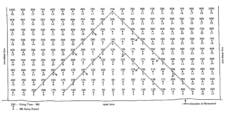
Here is a common surface mine layout with one free face. The numbers underneath the hole correspond to the delay sequence, first, second, third, and so forth. The numbers over the holes represent the millisecond delay for that hole.

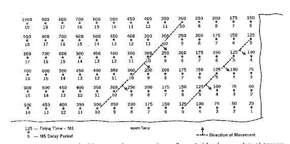
If there are two free faces, as in this case, a pattern like this is common.

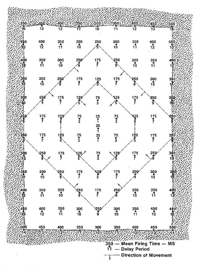
Occasionally, it is necessary to design a surface blast where there is no free face. Imagine an open field, and you are going to make the first blast so that material can be removed to initiate the surface mining cycle. By the way, the name given to this is box cut. Box cuts are a common means of accessing an orebody for underground mining, when the deposit is within a few hundred feet of the surface; and they are required as one of the initial development steps in most surface mining operations. A blasting pattern for a box cut is shown here.

These patterns can and will be modified ad nauseam to account for local geological anomalies, nearby structures such as pipelines or buildings and so on. With the few figures that we’ve examined here, you really do have comprehensive starting point for the design of your own pattern. You know how to: determine the burden, spacing, and stemming; choose an explosive or blasting agent; and lay out a pattern. One glaring gap in your knowledge base is how to achieve the desired timing delays. And so, we need to talk more about initiating the blast and the technology options available to us. We’ll do that in the next lesson.