6.5.1: Initiation of the Blast
Initiators contain high explosives that will detonate upon receiving an appropriate “signal.” If the blasting agent is cap-sensitive, then this action will set off the explosion. If it is not cap-sensitive, then the initiator will set off a primer, which will set off the blasting agent. In a typical pattern, there are many holes and each will have an initiator, and all of these holes need to be connected together, and a line must then be run to a safe location where the blaster will “throw the switch.”
Let’s talk about these initiators, their connection back to the blaster, and the method that the blaster uses to start the chain reaction.
Initiators can be classified into three categories. The categories and their primary characteristics are as follows:
- non-electric (75% of market and decreasing):
- immune to stray electricity,
- water is less of a problem than with other types,
- modest cost advantage, i.e., lower cost than other types;
- electronic (20% of market and increasing):
- allows for precise timing and sequencing,
- enhanced site security,
- immune to stray electricity,
- higher first cost and more complicated to use;
- electric (5% of market and decreasing):
- historically offered better control of timing and sequencing over non-electrics,
- simplicity in use,
- lack of site security,
- susceptible to stray electricity.
Non-Electric Initiation
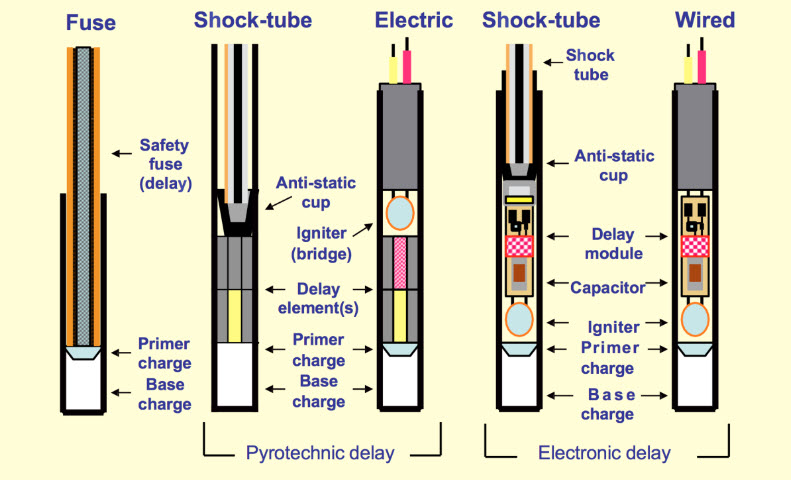
The predominate non-electric system uses shock tube and a non-electric blasting cap. Shock tube is plastic tube with a thin coating of a high explosive (think of a plastic drinking straw in which the inner wall of the straw has a thin coating of high explosive). Specially made plastic block connectors are used to join different lines (shock tubes) together; and, if desired, delays can be inserted at these connector blocks as well. Shock tube is set off with a machine that creates a spark or a mechanical device such as a spring-loaded hammer that strikes a starter resembling the tiny button primer at the base of a shotgun shell. Today, shock tube is used almost exclusively within the non-electric category. I don’t want to unnecessarily confuse the issue, but be aware that the nonelectric blasting caps used with shock tube can contain a pyrotechnic or an electronic time-delay mechanism within them. We’ll discuss blasting caps, both non-electric and electric, shortly.
Detonating cord contains a high explosive, such as PETN. It was used for trunk lines and downlines. Lines can be simply knotted together. It is initiated with a blasting cap (electric or nonelectric). The detonation velocity of PETN is 27,000 fps, and it creates a huge air blast. This is a big problem, and as a result, detonating cord has been largely replaced with shock tube.
There are two other types that no longer used in modern operations, but it's interesting to know what they are in case you read or hear about them. They are safety fuse and igniter cord. Allow me to tell you a bit more about safety fuse.
- Safety Fuse is a thin cloth fiber cord with a black-powder core. It has a uniform burn rate, for instance120 sec/yd. By varying the length, you could vary the time delay. Safety fuse was used to set off dynamite. It was also used in a lot of bad old cowboy movies in which a bad guy tied the good guy to a powder keg, and the powder keg was connected to a very long safety fuse. The bad guy lit the safety fuse and rode away. Since the safety fuse burns so slowly, the viewers got to watch it burn for a few minutes, giving the hero just enough time to swoop in and extinguish the safety fuse before it set off the powder keg!
Electronic Initiation
The popularity of electronic initiation is increasing because this system offers significant performance and safety advantages over other systems.
- Electronic caps consist of an electronic chip, a small capacitor, and a high explosive to detonate a primer or a cap sensitive explosive.
- Each electronic cap has a unique serial number with a bar code.
- Electronic caps are wired into the blasting circuit with insulated copper wire.
- An electronic blasting machine is required, and it communicates digitally with each cap.
- The electronic blasting machine is programmed to send a “fire” signal to each cap, based on the cap's serial number, according to a user-determined firing pattern.
- The wired circuit connecting the electronic caps together and to the blasting machine also carries an analog voltage to charge the capacitor in each cap. Charging of the capacitor begins after the blasting machine has “authorized” the cap to fire. The capacitor provides the energy to detonate the high explosive within the cap assembly. The authorization to each cap is possible because the unique serial number of each cap is known. The blaster can use a tag reader to record the serial number of each cap as each hole is loaded. This data can then be downloaded to the blasting machine.
- The time delay is determined electronically on a chip, and this is known as an electronic delay.
- The more precise timing and sequencing can be used to minimize ground vibration as well as to improve the outcome of the blast…but only if the underlying shot design is correct. The improved blasting performance available with an electronic initiation system will offset the higher initial cost of the caps.
- This system affords the user with a high degree of site security – a cap cannot be set off without a special machine and knowledge of the cap’s serial number.
It should be noted here that there is a type of electronic blasting cap that is made for use with shock tube, and that cap offers the advantage of more precise timing, but it does not offer the other benefits inherent to an electronic ignition system.
Electric Initiation
For decades, electric blasting caps were the only choice if you wanted to control more exactly the time delays. However, their susceptibility to stray electricity (think cell phones, two-way radios, and approaching electrical storms) has led to their rapid decline.
- Electric blasting caps have a bridge wire inside of them, embedded in a high explosive. When current from the blasting machine, or stray electricity, flows in the network of copper wires, the bridge wire melts, igniting a column of powder that controls the delay time, which then sets off a high-explosive base charge. This is known as pyrotechnic ignition. The base charge sets off a cap-sensitive blasting agent or a primer.
- The blasting circuit consists of many wires connected in series and in parallel, e.g., leg wires and trunk wires. A circuit analysis must be performed to ensure that sufficient current will be available to ensure a reliable blast.
The following diagram can be very helpful to solidify your understanding. The two different delay options, i.e., pyrotechnic and electronic, can show up in different initiation systems. That is sometimes confusing when you are learning this for the first time. Thus, it really is helpful to examine this diagram until you understand the operating principles and why they are named the way they are.

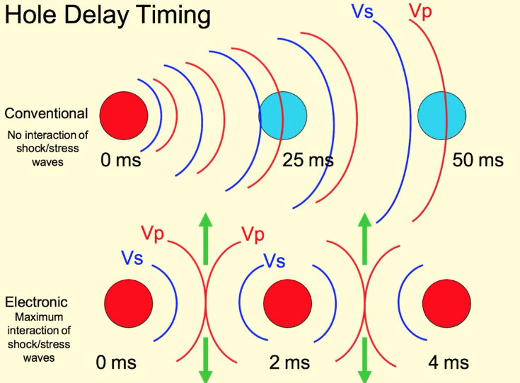
Historically, time delays were used to control the orderly movement of material through the free faces, as we have discussed; or to limit the amount of explosive being fired at any one time, which reduces the level of ground vibration. The advent of electronic initiation ushered in a new era in which we could more effectively take advantage of the physics.
Traditionally, time delays were available in 25 ms delays, which is adequate for the purposes that time delays have been used. The p and s vibration waves are shown in this figure for two cases: the first using traditional delays; and the second, using electronic delays that allow timing down to 2 ms. This allows us to create a positive interaction with the shock waves, and this gives us improved fragmentation.

It can be shown that the time delay, T, required between holes in a row is:
where:
T = the time delay between holes in a row, ms
S = distance between holes in a row, ft
Vp = compression or sonic wave velocity, ft/s
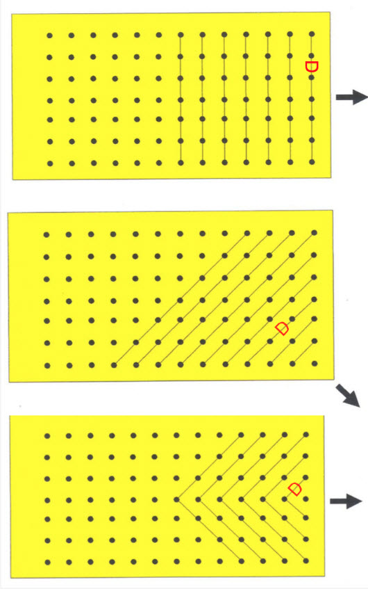
The row spacing distance used in the equation is the effective spacing, as shown for three different cases here. Note that the definition of a “row” is based on the firing sequence.

The value for Vp can be estimated from tables or by seeking advice from geophysical consultants. The value for Vp not only depends on the type of rock, but also the rock mass characterization. There are a few different characterization schemes in use, such as the Rock Quality Designation (RQD) or the Rock Mass Rating (RMR), but, in general, they take into account the number and spacing of the joints, the competency of the rock, and other characteristics of the rock mass. If you want a number for Vp so that you play with the equation, use 10,000 fps.
The potential for using electronic initiators to take advantage of the wave interaction is just being realized, and will become more common in the future. You now have knowledge of this, and can choose to take advantage of it in your future work.
Earlier in this lesson, I mentioned the idea of limiting the amount of explosive detonated in a given delay interval to lessen the impact of ground vibration. I’d like to look at that in more detail at this time.